EP0806358B1 - Verfahren und Vorrichtung zur Weitergabe von Gegenständen - Google Patents
Verfahren und Vorrichtung zur Weitergabe von Gegenständen Download PDFInfo
- Publication number
- EP0806358B1 EP0806358B1 EP97107588A EP97107588A EP0806358B1 EP 0806358 B1 EP0806358 B1 EP 0806358B1 EP 97107588 A EP97107588 A EP 97107588A EP 97107588 A EP97107588 A EP 97107588A EP 0806358 B1 EP0806358 B1 EP 0806358B1
- Authority
- EP
- European Patent Office
- Prior art keywords
- belt conveyor
- stacking belt
- packing
- articles
- carrier
- Prior art date
- Legal status (The legal status is an assumption and is not a legal conclusion. Google has not performed a legal analysis and makes no representation as to the accuracy of the status listed.)
- Expired - Lifetime
Links
- 238000000034 method Methods 0.000 title claims description 26
- 238000012546 transfer Methods 0.000 claims description 61
- 230000033001 locomotion Effects 0.000 claims description 54
- 238000012856 packing Methods 0.000 claims description 43
- 238000004806 packaging method and process Methods 0.000 claims description 30
- 230000015572 biosynthetic process Effects 0.000 claims description 10
- 238000012432 intermediate storage Methods 0.000 claims description 9
- 230000005540 biological transmission Effects 0.000 claims description 6
- 238000012545 processing Methods 0.000 claims description 4
- 210000000056 organ Anatomy 0.000 claims description 2
- 235000009508 confectionery Nutrition 0.000 description 64
- 238000011144 upstream manufacturing Methods 0.000 description 5
- 235000013736 caramel Nutrition 0.000 description 3
- 230000002093 peripheral effect Effects 0.000 description 3
- 230000008878 coupling Effects 0.000 description 2
- 238000010168 coupling process Methods 0.000 description 2
- 238000005859 coupling reaction Methods 0.000 description 2
- 238000013461 design Methods 0.000 description 2
- 238000001514 detection method Methods 0.000 description 2
- 238000003780 insertion Methods 0.000 description 2
- 230000037431 insertion Effects 0.000 description 2
- 238000004519 manufacturing process Methods 0.000 description 2
- 238000012549 training Methods 0.000 description 2
- 238000013459 approach Methods 0.000 description 1
- 229940112822 chewing gum Drugs 0.000 description 1
- 235000015218 chewing gum Nutrition 0.000 description 1
- 239000002131 composite material Substances 0.000 description 1
- 230000002950 deficient Effects 0.000 description 1
- 230000001419 dependent effect Effects 0.000 description 1
- 238000011161 development Methods 0.000 description 1
- 238000006073 displacement reaction Methods 0.000 description 1
- 230000002349 favourable effect Effects 0.000 description 1
- 238000007654 immersion Methods 0.000 description 1
- 210000000629 knee joint Anatomy 0.000 description 1
- 239000005022 packaging material Substances 0.000 description 1
- 238000012858 packaging process Methods 0.000 description 1
- 238000003825 pressing Methods 0.000 description 1
- 230000000717 retained effect Effects 0.000 description 1
- 238000003860 storage Methods 0.000 description 1
- 230000001360 synchronised effect Effects 0.000 description 1
Images


Classifications
-
- B—PERFORMING OPERATIONS; TRANSPORTING
- B65—CONVEYING; PACKING; STORING; HANDLING THIN OR FILAMENTARY MATERIAL
- B65B—MACHINES, APPARATUS OR DEVICES FOR, OR METHODS OF, PACKAGING ARTICLES OR MATERIALS; UNPACKING
- B65B35/00—Supplying, feeding, arranging or orientating articles to be packaged
- B65B35/10—Feeding, e.g. conveying, single articles
- B65B35/20—Feeding, e.g. conveying, single articles by reciprocating or oscillatory pushers
- B65B35/205—Feeding, e.g. conveying, single articles by reciprocating or oscillatory pushers linked to endless conveyors
-
- B—PERFORMING OPERATIONS; TRANSPORTING
- B65—CONVEYING; PACKING; STORING; HANDLING THIN OR FILAMENTARY MATERIAL
- B65B—MACHINES, APPARATUS OR DEVICES FOR, OR METHODS OF, PACKAGING ARTICLES OR MATERIALS; UNPACKING
- B65B35/00—Supplying, feeding, arranging or orientating articles to be packaged
- B65B35/10—Feeding, e.g. conveying, single articles
- B65B35/26—Feeding, e.g. conveying, single articles by rotary conveyors
-
- B—PERFORMING OPERATIONS; TRANSPORTING
- B65—CONVEYING; PACKING; STORING; HANDLING THIN OR FILAMENTARY MATERIAL
- B65B—MACHINES, APPARATUS OR DEVICES FOR, OR METHODS OF, PACKAGING ARTICLES OR MATERIALS; UNPACKING
- B65B35/00—Supplying, feeding, arranging or orientating articles to be packaged
- B65B35/30—Arranging and feeding articles in groups
- B65B35/40—Arranging and feeding articles in groups by reciprocating or oscillatory pushers
- B65B35/405—Arranging and feeding articles in groups by reciprocating or oscillatory pushers linked to endless conveyors
-
- B—PERFORMING OPERATIONS; TRANSPORTING
- B65—CONVEYING; PACKING; STORING; HANDLING THIN OR FILAMENTARY MATERIAL
- B65G—TRANSPORT OR STORAGE DEVICES, e.g. CONVEYORS FOR LOADING OR TIPPING, SHOP CONVEYOR SYSTEMS OR PNEUMATIC TUBE CONVEYORS
- B65G29/00—Rotary conveyors, e.g. rotating discs, arms, star-wheels or cones
-
- B—PERFORMING OPERATIONS; TRANSPORTING
- B65—CONVEYING; PACKING; STORING; HANDLING THIN OR FILAMENTARY MATERIAL
- B65G—TRANSPORT OR STORAGE DEVICES, e.g. CONVEYORS FOR LOADING OR TIPPING, SHOP CONVEYOR SYSTEMS OR PNEUMATIC TUBE CONVEYORS
- B65G47/00—Article or material-handling devices associated with conveyors; Methods employing such devices
- B65G47/74—Feeding, transfer, or discharging devices of particular kinds or types
- B65G47/82—Rotary or reciprocating members for direct action on articles or materials, e.g. pushers, rakes, shovels
-
- B—PERFORMING OPERATIONS; TRANSPORTING
- B65—CONVEYING; PACKING; STORING; HANDLING THIN OR FILAMENTARY MATERIAL
- B65G—TRANSPORT OR STORAGE DEVICES, e.g. CONVEYORS FOR LOADING OR TIPPING, SHOP CONVEYOR SYSTEMS OR PNEUMATIC TUBE CONVEYORS
- B65G47/00—Article or material-handling devices associated with conveyors; Methods employing such devices
- B65G47/74—Feeding, transfer, or discharging devices of particular kinds or types
- B65G47/84—Star-shaped wheels or devices having endless travelling belts or chains, the wheels or devices being equipped with article-engaging elements
- B65G47/846—Star-shaped wheels or wheels equipped with article-engaging elements
- B65G47/847—Star-shaped wheels or wheels equipped with article-engaging elements the article-engaging elements being grippers
Definitions
- the invention relates to a method for the transfer of objects, in which the items are fed individually and removed in groups.
- the invention further relates to a device with the features of the preamble of claim 11.
- Such packaging machines based on the "rotation principle" of the transfer elements, in particular candy packaging machines, can High-performance area with packaging speeds of up to approx. 1,500 Work pieces per minute and are extremely efficient. Creates difficulties the same with such high-performance packaging machines economical further process design, e.g. to form packaged into bars Objects.
- a method and a device of the type mentioned at the outset are from DE-A1-23 35 026 known. However, there are several with the help of a pair of grippers Single packs gripped and bundled at once, in bundled condition packed and then in outer packaging transported on a conveyor belt filed.
- the invention is therefore based on the object of a method and a device of the type mentioned at the beginning, which allow objects, possibly even after previous individual packaging, at high speed Organize groups and make them stackable, possibly for a first or Further packaging to bars.
- the aforementioned object is achieved according to the invention solved by a method comprising the features of claim 1.
- the inventive method has the advantage that it is based on the promotion of the objects mainly on circular segment sections, such as. Candy, possible through a packaging machine, under Maintaining this way of working, which enables high-performance operation arrange individual objects into groups to prepare one Rod formation, in which the objects are packed one after the other or unwrapped.
- those on the rotating Carrier arranged holding jaws for the objects around a substantially Axis extending parallel to the axis of rotation of the carrier, wherein this relative pivoting movement of the pairs of holding jaws to the basic rotational movement of the carrier in an advantageous manner a speed adjustment allowed between the carrier and the downstream stacking belt conveyor, wherein the speed ratio is widely variable.
- the rotational speed of the carrier is preferably greater than a conveying speed, in particular circulation speed, a stacking belt of the Stacking belt conveyor.
- each group of objects grouped in the stacking belt conveyor by a substantially perpendicular to the conveying direction of the stacking belt conveyor working ejection device in a delivery area from the stacking belt conveyor given, preferably a pressure delivery principle is applied.
- the group of objects is preferably essentially one Intermediate storage device movable parallel to the conveying direction of the stacking belt conveyor delivered, of which in turn using a train promotion principle the objects together from the intermediate storage device to a feed member a processing machine, especially a packaging machine, such as. be supported by a pole packer.
- the aforementioned device is particularly advantageous since it is retained an individual treatment of objects in a packaging machine and while maintaining the principle of "rotating" transmission creates a large number of objects with extremely high working speeds to put them in groups and a further treatment, e.g. to form rods from a large number of individual, pre-grouped objects, packaged or unwrapped to undergo.
- the stacking belt conveyor is a rotating stacking belt with a plurality of projections on, to form the packing compartments with a stationary opposite between a receiving section of the stacking belt conveyor and a delivery section the same arranged counter bearing.
- the pairs of holding jaws of the carrier in turn, move Holding jaws between which the object in question each is directly received and supported, the holding jaws separate from the associated ones, which hold the holding jaws Swivel housings movable and in particular in relation to them are rotatable so that it is possible by the holding jaws detected objects on the way between the recording area of the carrier and the delivery area thereof to the Stacking belt conveyor e.g. turn by 90 °.
- This can e.g. prismatic objects in a flat orientation initially gripped by the holding jaws, but in an upright orientation for group formation and stacking at the Stacking belt conveyors are passed on (or vice versa).
- the device is in a delivery area of the stacking belt conveyor a transverse thrust device as an ejection device for pushing out the objects conveyed in groups provided from the packing compartments of the stacking belt conveyor.
- This ejection device is used in groups Transverse displacement of the objects for further packaging. Dependent on from a control signal to the cross thruster can do this even if it detects non-quality objects be stopped so that one is incomplete or recognized as at least partially qualitatively insufficient Stage in the conveying direction of the stacking belt conveyor becomes.
- the stacking belt occupies in the output area of the stacking belt conveyor, movable is.
- the rotating carrier is preferably one between a rotating one Packing head and the stacking belt conveyor arranged Transfer head, which rotates around a stationary axis Housing on which a plurality of pairs of holding jaws can be pivoted is included, with a swivel control of the Pairs of holding jaws and a separate rotary movement of the holding jaws through a stationary, adjustable jointly with the axis Cam disc arrangement takes place.
- packaging of candies 205 of prismatic geometry e.g. of soft or hard caramels represents, especially while preparing the individually packaged Candy 205 for feeding one - here not shown - bar packer, goes without saying not limited to handling this type of item, but can be used for a variety of others, especially small items that should be packed and which in particular are either already individually prepacked or also unpacked into groups and especially to Poles to be packed, find application.
- individual elements of the overall device e.g. a transfer head, also in other contexts and machine links be used.
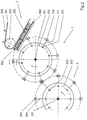
- the transfer head 1 provided the, downstream of the packing head 2 and arranged upstream of a stacking belt conveyor 3, likewise has a housing 102 rotating about a stationary axis 101, on the pair of jaws pivotally mounted about axes of rotation 103 104 are pivotally mounted, rotated 90 ° in relation on the orientation of the pairs of pack jaws 204 of the pack head 2 arranged to hold the individually wrapped candies 205 of the same speed, but with opposite direction of rotation rotating packing head 2 and for delivery are provided on a stacking belt conveyor 3, the with significantly lower conveying speed (approx. 1/3 of the circulating speed of the rotating housing 102 of the transfer head 1 arranges the individually wrapped candies in groups.
- the group-forming stacking belt conveyor 3 For a smooth work is an adjustment the rotational speed of the respective pair of holding jaws with the individually wrapped candy 205 to the conveying speed the group-forming stacking belt conveyor 3 is required, this being by swivel housing 117, i.e. through the around the Rotation axis 103 pivotable articulation of the holding jaw pairs 104 he follows.
- the stacking belt conveyor points to the formation of the groups 3 shows a stacking belt 301 with drivers 302, the stacking belt is guided over a deflection roller 303 and in the area the reception of the candies 205 from the transfer head 1 and Further transport of the candy groups has a counter bearing 304.
- the packing head 2 the one Variety of around the stationary axis 201 on the rotating one Housing 202 has pivotable pack jaws 204, which individually wrapped candies 205 upstream of the stacking belt conveyor 3 arranged transfer head 1 fed to the candies 205 by the holding jaw pairs 104, which are pivotable the housing 102 rotating about the stationary axis 101 are, picks up and leads to the stacking belt conveyor 3, arranged tangentially in the orbit of the candies 205 is.
- the transfer head 1 also has the ability to sweets in their position by 90 ° so that they are not only in the Flat format (as recorded) can be passed on but also for the upright processing of the stacking belt conveyor 3 can be supplied.
- the stacking belt conveyor reveals the rotational speed 3 a significantly lower working speed, preferably at a maximum of about 50% of the working speed the upstream conveyor 1 and 2 is (in general 1/3 of this speed of work), and education Groups A, B of candies 205 are used for further packaging to rods.
- the stacking belt conveyor 3 has the stacking belt 301 with the drivers 302, which are in connection with the counter bearing 304 form storage compartments 305, in which in the present In each case, 3 candies 205 taken side by side can be (Fig. 1) or 5 candies 205 edgewise can be recorded side by side (Fig. 2, Fig. 13-15).
- the stacking belt 301 is over the deflecting rollers 303 continuously circulating.
- a conveyor 5 which is formed here by a feed belt 501 similar to the stack belt 301 by the driver 502 forms individual transport compartments 503 in which the supplied Groups A, B of candies are intermittently removed and e.g. be fed to a bar packer.
- a feed chain 505 as a conveyor and feed path for subsequent packaging of several groups A, B of objects as shown in Figs. 13-15 is.
- a transfer device 4 provided in the sense of cross-funding between the stacking belt conveyor 3 and the further conveying device 5 works and explained in more detail below becomes.
- the transfer head 1 is therefore in a special way to ensure such a function, as follows is explained with reference to FIGS. 2-11.
- FIG. 2 A procedural procedure with the transfer rotated by 90 ° Sweets 205 on the stacking belt conveyor 3 are shown in FIG. 2.
- the sweets On the way of receiving the candies 205 from the packing head 2 by the pairs of holding jaws 104 of the transfer head 1 the sweets must be delivered to the stacking belt conveyor 3 205 therefore still 90 ° with simultaneous detection by the Holding jaw pairs 104 are rotated. Preferably done this rotational movement only at the end, i.e. together with one opposing axial movement of the pairs of holding jaws 104 for Release of the candy 205 to the stacking belt 301 of the stacking belt conveyor 3, so that the jaw pairs 104 not just one Subject to axial movement, but at the same time by one Rotational movement of the pairs of holding jaws 104 is superimposed, for rotating the candies 205 in the upright position.
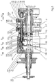
- the design of the transfer head 1 is shown below with the device for rotating the pairs of holding jaws 104 3-11 explained in more detail.
- the transfer head 1 has the central, stationary, however axis 101 rotatable in the circumferential direction, in particular by 180 ° on, which is between a stationary housing 107 and a Bearing plate 108 extends.
- On the stationary axis 101 is rotatably connected to the axis 101, a cam arrangement 109 as part of a motion control device for the holding jaw pairs 104 fixed.
- This cam arrangement 109 consists of a plurality of on the stationary axis 101 cam disks 110, 111, 112, 113 arranged in sequence, 114. They are preferred together with the stationary axis 106 swivels through 180 ° to change the movement pattern for a rotating movement of the individual pairs of holding jaws 104 set up, as will be explained below becomes.
- cam plates 110-114 could also be structurally united or separately via e.g. a common adjusting sleeve, which are rotatably received on the stationary axis 106 is adjustable relative to this by a certain angle his.
- Opposing swivel housing 117 is a pair of holding jaws 104 with the holding jaws 104a, 104b, wherein each holding jaw 104a, 104b is axially movable around the candy 205 pressing on opposing surfaces with frictional engagement and grip by a spring 106 or to release.
- the holding jaws 104a, 104b are also one Holding jaw axis A rotatable around the gripped candy 205 (or another item that is being processed) in a position opposite the receiving position, preferably by 90 ° forward the rotated position (e.g. upright after flat recording).
- the motion control device for each pair of holding jaws 104, the holding jaws 104a, 104b both opposing Axial movement as well as a rotary movement around their Gives the jaw axis A, the cam disks 110, 111, 112, the cams 111 and 112 the axial movement the outer holding jaw 104b (cam disk 111) or the axial movement of the inner holding jaw 104a (cam disc 112) control.
- the control of the axial movement for the inner holding jaw 104a takes place via the control roller of the also by radial Guide body 123 radially guided cam lever 122 on the Sleeve 124, with which the radial guide body 123 rotatably are connected, the sleeve 124 with the inner holding jaw 104a for transmitting the axial movement from the sleeve 124 is directly connected to this holding jaw 104a.
- the cam lever 122 is in insert with its other end 115 of the base housing 102 rotatably mounted.
- pivotable Holding jaw pairs 104 also additionally with a rotary movement to equip the holding jaw axis A to the opposite one Pick-up position from the upstream packing head 1 e.g.
- Each delivery position for candies 205 is rotated by 90 ° Holding jaw 104a, 104b in one piece with a toothed segment 126, 127 provided that in meshing engagement with counter-tooth segments 128, 129, which is once non-rotatable for the outer holding jaw 104b on the shaft 125 or for the inner holding jaw 104a are received on the sleeve 124.
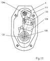
- FIG. 11 The partial sectional view of FIG. 11 (with removed Swivel housing cover) once again illustrates the holding jaws 104a, 104b of the transfer head 1 additionally awarded Degree of freedom and shows the transmission elements for the Transfer of an additional rotary movement, here to the outside Holding jaw 104b about the holding jaw axis A, wherein it can be seen that by an integral connection of the toothed segment 127 with the holding jaw 104b of this by meshing with the counter-toothed segment 129, a rotary movement about the holding jaw axis A can be awarded when the shaft is twisted 125, with which the counter-tooth segment 129 is firmly connected.
- the gap is a holding finger for each swivel housing 117 137 in a central radial plane B between the two holding jaws 104a, 104b, practically in plant or immediately adjacent provided for the respective article, here candy 205, the reliable support and handover of the candy 205 from the transfer head 1 to the successor device, here the stacking belt 301 of the stacking belt conveyor 3 is supported.
- FIG. 11a and 11b schematically the transfer of the individually wrapped candies 205 from the transfer head 1 for one Holding jaw pair shown schematically, in Fig. 11a for the formation of groups for upright packaging under rotation the holding jaws 104a, 104b (as described above) and in Fig. 11b for the formation of groups in a flat pack (no additional rotation of the holding jaws 104a, 104b), whereby especially for Fig. 11a it is clear that the rotary movement the holding jaws 104a, 104b about the holding jaw axis A in Area of transfer to the stacking belt conveyor 3, i.e. under Superimposition of the pivoting movement that the holding jaws 104a, Execute 104b with the swivel housing 117.
- the counter bearing 304 has an insertion slope 304a and the holding finger 137 may be used to support the handover process ready.
- Group A, B is then moved by driver 302 along the counter holder in a packing compartment 305 thus formed promoted away.
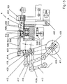
- the transfer device 4 has a transverse pushing device 401 with a pusher 402, the width of which in the conveying direction of the stacking belt 301 approx. the total width of a group A, B of candies corresponds to 205, i.e. is slightly less than that Distance between two subsequent drivers 302 of the stacking belt 301, so that the pusher 402 in a between the Carrier 302 and the counter bearing 304 formed packing compartment 305 immerse and collectively group A, B of candies 205 in Can convey out the transverse direction from the stack conveyor 3 (see also Figs. 13 and 15).
- the pusher 402 a correspondingly combined, consisting of exhaust longitudinal and transverse movement composite control movement, preferably in the area before or after immersion with Vertical motion control components are combined to create a to obtain favorable movement behavior of the pusher 402.
- the control curve for the pusher 402 is 403 indicated schematically. The movement of the pusher 402 in The broken line 403a in FIG Fig. 13.
- the drive device for the pusher 402 is not shown in detail, is preferably the Pusher with a hydraulic between a working and a non-working position switchable, preferably hydraulic controlled knee joint controlled so that the drive of the pusher depending on an observation of the Grouping of the candy pieces or a quality observation the individual packaging of the candies 205 are shut down can. Due to the continuous conveying principle of the stacking belt conveyor 3 would be considered faulty or so incompletely recognized groups of candies without actuation of the pusher 402 simply to the rear in the conveying direction of the stacking belt 301 (arrow X in FIG.
- the pusher 402 works on an intermediate plate 404, which correspond to the circulating speed of the stacking belt 301 also horizontally in the transfer area, i.e. in the work area of the expeller 402 at one of the speeds of the stack belt 301 corresponding speed horizontally is moved (the withdrawal movement to the starting position takes place more quickly).
- a drive device for the intermediate plate 404 is in the schematic representations according to FIG. 13 and 15 at 405.
- the intermediate plate 404 works to transfer the group Candy 205 together on the feed belt 501 or the feed chain 505 (Fig. 15) together a transverse pull device 406, the for the defined delivery of each group A, B of candies 205 has a counterholder 407 and a gripper part 408 which by a common drive lever 409 (see FIG. 15) in its Movement can be controlled and interact with each other as in 15 is shown to form a transport compartment 410 in which the respective group A, B is located on the intermediate plate 404, to then be pulled down from this and onto the feed belt 501 or the feed chain 505 to be pulled as this will be explained with reference to FIGS. 14 and 15.
- the transport compartment 410 communicated through the counter holder 407 with the gripper part 408 on the intermediate plate 404 and formed downstream of it, can also be designed larger so that e.g. two groups of candies 205 from the Stacking belt conveyor 3 in a row on the intermediate plate 404 are pushed out by the pusher 402 and only then the gripper part 408 behind the last one pushed out Group intervenes and the two following groups together conveyed onto the feed belt 501 or the feed chain 505 and then intermittently with this traction device be promoted.
- the counterholder 407 essentially performs a horizontal movement between the feed belt 501 or the feed chain 505 (Fig. 15) and the intermediate plate 404, controlled by the common drive lever designed as a rocker arm 409, the fixed with a hollow shaft, not shown here is connected and via a swivel 412 a counter-holder rocker 413 moves, with a control lever 413a of the counter-holder rocker 413 a holder 414 is connected, which in turn firmly holds the counter-holder 407. Furthermore, the drive lever 409 via a swivel 420 motion-transmitting connected to a holder 418 of the gripper part 408, the one additional gripping stroke movement via a control lever 419 and a control pad 416 is awarded.
- the Feed chain 505 for intermittently feeding the groups A, B points to a bar packer (not shown here) connected to the individual chain links in the usual way
- Carrier 506 the transport compartments with carrier plates for groups A, B of candies 205 on the supply chain 505, which is accommodated in a housing 509, the top plate 508 a transport slideway for the groups A, B forms.
- Fixed side guides for the feed conveyor 5 are designated in FIG. 13 by 510 and 511.
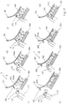
- Figure 14 illustrates in steps a - c in schematic Top views each show a transfer process from the continuous Stacking belt conveyor 3 to the intermittent conveyor Chain conveyor 5, wherein in Fig. 14a (rest position) a group A is on the stacking belt 301 of the stacking belt conveyor 3 is in the position between two drivers 302, in which the pusher 402 attack group A and the group can pass onto the intermediate plate 404. In this Position is also an already transferred one Group B in the transport compartment between counterholder 407 and Gripper part 408 between two driver plates 507 of the chain conveyor 5.
- FIG. 14b the feed chain 505 is advanced one step and the counterholder 407 and the gripper part 408 reach through an empty transport area between two Driver plates 507 through towards the intermediate plate 404.
- FIG. 14c it is shown how the pusher 402 the group A on the intermediate plate 404 and in this here first transport compartment 410 formed by the counter-holder 407 inserts. Then the gripper part 408 with the Gripper nose 408a in a lifting gripping movement over group A reach away and from the opposite side with the counterholder 407 onto the top plate 508 of the move the chain conveyor having the feed chain 505. The gripper part 408 is covered in FIG. 14c (since covered by the counter-holder 407) not shown.
- the pusher 402 is not operated and thanks the continuous promotion of the stacking belt conveyor 3 run the defective products simply in the conveying direction of the stacking belt 301 from the stacking belt conveyor 3.
Landscapes
- Engineering & Computer Science (AREA)
- Mechanical Engineering (AREA)
Description
- Fig. 1
- eine Vorrichtung zur Weitergabe von Gegenständen nach einem Ausführungsbeispiel der Erfindung, wobei einzelne Gegenstände, hier Bonbons, zunächst einzelverpackt, anschließend eine Gruppenbildung der einzelverpackten Bonbons erfolgt und schließlich die Gruppen einem Zuführungsförderer für einen Stangenpacker zugeführt werden und für Flachpackung,
- Fig. 2
- eine schematische Darstellung der Weitergabevorrichtung nach Fig. 1 im Bereich einer Zuförderung der einzelverpackten Gegenstände zu einem Stapelbandförderer über einen Übergabekopf von einem Packkopf unter 90°-Drehung der Gegenstände durch den Übergabekopf, abweichend von dem Ausführungsbeispiel nach Fig. 1 (Hochkantpackung),
- Fig. 3
- einen Längsschnitt durch einen Übergabekopf in einer Bonbon-Verpackungsmaschine,
- Fig. 4
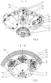
- eine Teilschnitt-Darstellung entlang einer Linie A-A nach Fig.1,
- Fig. 5
- eine Teilschnitt-Darstellung entlang einer Linie B-B nach Fig. 1,
- Fig. 6
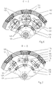
- eine Teilschnitt-Darstellung entlang einer Linie C-C nach Fig.1,
- Fig. 7
- eine Teilschnitt-Darstellung entlang einer Linie D-D nach Fig. 1,
- Fig. 8
- eine Teilschnitt-Darstellung entlang einer Linie E-E nach Fig.1,
- Fig. 9
- eine Teilschnitt-Darstellung entlang einer Linie F-F nach Fig. 1,
- Fig. 10
- eine Teilschnitt-Darstellung entlang einer Linie G-G nach Fig.1,
- Fig. 11
- eine Ansicht ähnlich derjenigen in Fig. 2 für eine einzelne Haltebacke (äußere Axialansicht), und
- Fig. 12
- eine schematische Darstellung für den Bewegungsablauf bei der Bildung der Gruppierung an der Übergabestelle zwischen Übergabekopf und Stapelbandförderer für die Herstellung von Hochkantpackungen (Fig. 12a) und Flachpackungen (Fig. 12b),
- Fig. 13
- eine Draufsicht auf eine Übergabevorrichtung für die Weitergabevorrichtung nach Fig. 1,
- Fig. 14a - 14c
- eine Darstellung der Phasen einer Ausförderung einer Gruppe von Gegenständen aus einem Stapelbandförderer nach einer Ausführungsform gemäß Fig. 2 (Hochkantpackung) bzw. Fig. 12a zu einer Weiterfördereinrichtung, und
- Fig. 15
- eine Querschnittsdarstellung der Übergabevorrichtung nach Fig. 14 in schematischer Darstellung.
Claims (25)
- Verfahren zur Weitergabe von Gegenständen (205), insbesondere für Verpackungsmaschinen, bei dem die Gegenstände einzeln zugeführt und in Gruppen (A,B) abgeführt werden, dadurch gekennzeichnet, daß jeder Gegenstand (205) einzeln zwischen gegenüberliegenden Haltebacken (104), die an einem rotierenden Träger (1) schwenkbar gelagert sind, aufgenommen wird, mit dem Träger (1) in Umfangsrichtung desselben transportiert wird und von diesem (1) einzeln im wesentlichen tangential an einen Stapelbandförderer (3) abgegeben wird, der zwischen einem Stapelband und einem Gegenhalter (304) gebildete Packfächer (305) umfaßt, wo die einzelnen Gegenstände (205) in den Packfächern des Stapelbandförderers benachbart angeordnet in Gruppen (A,B) gestapelt werden und anschließend gruppenweise durch den Stapelbandförderer (3) weiterbewegt und gruppenweise von diesem abgegeben werden.
- Verfahren nach Anspruch 1, dadurch gekennzeichnet, daß die Haltebacken (104) eine Schwenkbewegung an dem Träger (1) um eine im wesentlichen parallel zur Drehachse (101) des Trägers (1) verlaufende Achse (103) ausführen.
- Verfahren nach Anspruch 1 oder 2, dadurch gekennzeichnet, daß eine Umlaufgeschwindigkeit des Trägers (1) größer ist als eine Fördergeschwindigkeit eines Stapelbandes (301) des Stapelbandförderers (3).
- Verfahren nach zumindest einem der vorhergehenden Ansprüche 1 bis 3, dadurch gekennzeichnet, daß jede Gruppe (A, B) von Gegenständen (205) aus dem Stapelbandförderer (3)durch eine im wesentlichen rechtwinklig zur Förderrichtung (X) des Stapelbandförderers (3) arbeitende Ausstoßvorrichtung (402) in einem Abgabebereich aus dem Stapelbandförderer (3) in einer Druckförderung abgegeben wird.
- Verfahren nach zumindest einem der vorhergehenden Ansprüche 1 bis 4, dadurch gekennzeichnet, daß die Gruppen (A, B) von Gegenständen (205) auf eine im wesentlichen parallel zur Förderrichtung (X) des Stapelbandförderers (3) bewegbare Zwischenlagervorrichtung (404) abgegeben werden.
- Verfahren nach Anspruch 5, dadurch gekennzeichnet, daß die Gruppen (A, B) von Gegenständen (205) gemeinsam durch eine Zugförderung von der Zwischenlagervorrichtung (404) auf ein, insbesondere intermittierend arbeitendes Zuführungsorgan (501, 505) einer Verarbeitungsmaschine, insbesondere Verpackungsmaschine, gefördert werden.
- Verfahren nach zumindest einem der vorhergehenden Ansprüche 1 bis 6, dadurch gekennzeichnet, daß die Gegenstände (205) durch die Haltebacken (104) des rotierenden Trägers (1) von Packbacken (204) eines im wesentlichen mit der Umlaufgeschwindigkeit des Trägers (1) rotierenden Packkopfes (2) aufgenommen werden.
- Verfahren nach Anspruch 7, dadurch gekennzeichnet, daß bei der Übergabe der Gegenstände (205) von den Packbacken (204) des Packkopfes (2) zu den Haltebacken (104) des Trägers (1) die Haltebacken (104) um 90° versetzt an dem Gegenstand (205) in bezug auf die Halterung der Gegenstände (205) durch die Packbacken (204) des Packkopfes (2) angreifen.
- Verfahren nach zumindest einem der vorhergehenden Ansprüche 5 bis 8, dadurch gekennzeichnet, daß die Umlaufgeschwindigkeiten des Packkopfes (2) und des Trägers (1) im wesentlichen gleich sind, während die Fördergeschwindigkeit des Stapelbandförderers (3)höchstens die Hälfte der Umlaufgeschwindigkeit des Packkopfes (2) oder Trägers (1) beträgt.
- Verfahren nach zumindest einem der vorhergehenden Ansprüche 1 bis 9, dadurch gekennzeichnet, daß zuminest eine Haltebacke (104a, 104b) jedes Haltebackenpaares (104) relativ zu der Drehachse (103) um eine Haltebackenachse (A) drehbar ist.
- Vorrichtung zur Weitergabe von Gegenständen, insbesondere für Verpackungsmaschinen, mit Haltebackenpaaren, die an einem rotierenden Träger (1) schwenkbar gelagert sind, zur einzelnen Erfassung eines einzelnen Gegenstandes (205) zwischen den Haltebacken (104) eines Haltebackenpaares in einem Aufnahmebereich des Trägers, der Bewegung des Gegenstandes mit dem Träger in Umfangsrichtung desselben und Abgabe des Gegenstandes in einem Abgabebereich des Trägers, gekennzeichnet durch einen stromab des Trägers (1) angeordneten Stapelbandförderer (3) mit Packfächern (305) zur gruppenweisen Aufnahme der einzeln durch die Haltebackenpaare (104) des Trägers (1) zugeführten Gegenstände (205) in gestapelter Anordnung nebeneinander, wobei die Packfächer (305) zwischen einem umlaufenden Stapelband (301) und einem Gegenlager (304) gebildet werden.
- Vorrichtung nach Anspruch 11, dadurch gekennzeichnet, daß das Stapelband (301) des Stapelbandförderers (3) eine Mehrzahl von Mitnehmern (302) zur Bildung der Packfächer (305) aufweist, mit einem stationär gegenüberliegend zwischen einem Aufnahmeabschnitt des Stapelbandförderers (3) und einem Abgabeabschnitt desselben angeordneten Gegenlager (304).
- Vorrichtung nach Anspruch 12, dadurch gekennzeichnet, daß die Bildung der Packfächer (305) im wesentlichen tangential zu einem Bewegungsweg der Haltebackenpaare (104) erfolgt.
- Vorrichtung nach zumindest einem der vorhergehenden Ansprüche 11 bis 13, dadurch gekennzeichnet, daß die Haltebackenpaare (104) bewegliche Haltebacken (104a, 104b) aufweisen, zwischen denen der Gegenstand (205) aufgenommen ist.
- Vorrichtung nach Anspruch 14, dadurch gekennzeichnet, daß die Haltebacken (104a, 104b)separat von den zugehörigen Lagermitteln, insbesondere einem Schwenkgehäuse (117) beweglich, insbesondere gegenüber diesen verschwenkbar sind.
- Vorrichtung nach zumindest einem der vorhergehenden Ansprüche 11 bis 15, dadurch gekennzeichnet, daß in einem Abgabebereich des Stapelbandförderers (3) eine Ausstoßvorrichtung (402) zum Ausschieben der gruppenweise geförderten Gegenstände (205) aus den Packfächern (305) des Stapelbandförderers (3) vorgesehen ist.
- Vorrichtung nach Anspruch 16, dadurch gekennzeichnet, daß in Verbindung mit der Ausstoßvorrichtung (402) eine im wesentlichen parallel zur Förderrichtung (X) des Stapelbandes (301) im Ausgabebereich des Stapelbandförderers (3) bewegbare Zwischenplatte (404) vorgesehen ist.
- Vorrichtung nach Anspruch 17, dadurch gekennzeichnet, daß stromab der Zwischenplatte (404) ein Zuführzugmittel (501, 505) zur gruppenweisen Zuführung der Gegenstände (205) zu einer Verpackungsmaschine vorgesehen und zwischen Zwischenplatte (404) und Zufühzugmittel (501, 505) eine Übergabevorrichtung (4) angeordnet ist.
- Vorrichtung nach zumindest einem der vorhergehenden Ansprüche 11 bis 18, dadurch gekennzeichnet, daß der rotierende Träger ein Übergabekopf (1) ist, der ein um eine stationäre Achse (101) rotierendes Gehäuse (102), an dem schwenkbar die Mehrzahl von Haltebackenpaaren (104) aufgenommen sind, aufweist, wobei eine Bewegungssteuerung der Haltebackenpaare (104) durch eine stationäre, gemeinsam mit der Achse (101) verdrehbare Kurvenscheibenanordnung (109) erfolgt.
- Vorrichtung nach Anspruch 19, dadurch gekennzeichnet, daß der Übergabekopf (1)zwischen einem rotierenden Packkopf (2) mit einer der Anzahl der Haltebackenpaare (104) an dem Übergabekopf (1) entsprechenden Anzahl von Packbacken (204) und dem Stapelbandförderer (3) angeordnet ist.
- Vorrichtung nach Anspruch 20, dadurch gekennzeichnet, daß die Umlaufgeschwindigkeiten von Packkopf (2) und Übergabekopf (1) im wesentlichen gleich sind.
- Vorrichtung nach zumindest einem der vorhergehenden Ansprüche 19 bis 21, dadurch gekennzeichnet, daß der Packkopf (2) Teil einer die Gegenstände (205) einzeln verpackenden Verpackungsmaschine ist, deren Antriebseinrichtung gleichzeitig die Antriebseinrichtung für den Übergabekopf (1) und den Stapelbandförderer (3) ist.
- Vorrichtung nach zumindest einem der vorhergehenden Ansprüche 19 bis 22, dadurch gekennzeichnet, daß die Förderung der Gegenstände (205) durch den Übergabekopf (1) über einen Umfangswinkel von ca. 180° zwischen dem Packkopf (2) und dem Stapelbandförderer (3) erfolgt.
- Vorrichtung nach zumindest einem der vorhergehenden Ansprüche 19 bis 23, dadurch gekennzeichnet, daß die Haltebacken (104) des Übergabekopfes (1) im wesentlichen rechtwinklig zu paarweise an dem Packkopf (2) gelagerten Packbacken (204) angeordnet sind.
- Vorrichtung nach Anspruch 18, dadurch gekennzeichnet, daß die Übergabevorrichtung (4) eine Querschubvorrichtung (401) zum Ausstoßen einer Gruppe (A, B) von Gegenständen (205) aus einem Packfach (305) des Stapelbandförderers (3) im wesentlichen quer zu einer Förderrichtung (X) des Stapelbandförderers (3) auf eine Zwischenlagervorrichtung (404) und eine Querzugvorrichtung (406) zum Aufnehmen der Gruppe (A, B) von Gegenständen von der Zwischenlagervorrichtung (404) zu einer Weiterfördereinrichtung (5) aufweist.
Applications Claiming Priority (2)
| Application Number | Priority Date | Filing Date | Title |
|---|---|---|---|
| DE19618511 | 1996-05-08 | ||
| DE19618511A DE19618511A1 (de) | 1996-05-08 | 1996-05-08 | Verfahren und Vorrichtung zur Weitergabe von Gegenständen |
Publications (2)
| Publication Number | Publication Date |
|---|---|
| EP0806358A1 EP0806358A1 (de) | 1997-11-12 |
| EP0806358B1 true EP0806358B1 (de) | 1999-08-18 |
Family
ID=7793718
Family Applications (1)
| Application Number | Title | Priority Date | Filing Date |
|---|---|---|---|
| EP97107588A Expired - Lifetime EP0806358B1 (de) | 1996-05-08 | 1997-05-07 | Verfahren und Vorrichtung zur Weitergabe von Gegenständen |
Country Status (2)
| Country | Link |
|---|---|
| EP (1) | EP0806358B1 (de) |
| DE (2) | DE19618511A1 (de) |
Cited By (5)
| Publication number | Priority date | Publication date | Assignee | Title |
|---|---|---|---|---|
| CN103274079A (zh) * | 2013-05-17 | 2013-09-04 | 杭州中亚机械股份有限公司 | 一种异向分组装置 |
| DE102014005959A1 (de) | 2013-04-30 | 2014-10-30 | Theegarten-Pactec Gmbh & Co. Kg | Verfahren zur Gruppierung von Artikeln zu Artikelstangen und Gruppiereinrichtung sowie Verpackungsmaschine mit einer solchen nebst Steuereinrichtung für Produkt-Halteeinrichtungen |
| DE102014005942A1 (de) | 2013-04-30 | 2014-10-30 | Theegarten-Pactec Gmbh & Co. Kg | Verfahren zur Gruppierung von Artikeln zu Artikelstangen und Gruppiereinrichtung sowie Verpackungsmaschine mit einer solchen |
| CN105966672A (zh) * | 2016-07-04 | 2016-09-28 | 江苏仅包装技术有限公司 | 一种循环推手机构 |
| EP4269293A1 (de) * | 2022-04-25 | 2023-11-01 | Theegarten-Pactec GmbH & Co. KG | Verfahren und vorrichtung zur vereinzelung und verarbeitung kleinstückiger produkte |
Families Citing this family (10)
| Publication number | Priority date | Publication date | Assignee | Title |
|---|---|---|---|---|
| DE10027506A1 (de) * | 2000-06-06 | 2001-12-13 | Focke & Co | Verfahren und Vorrichtung zum Bilden und Verpacken von Gruppen einzelner Gegenstände |
| DE10217899A1 (de) * | 2002-04-22 | 2003-11-06 | Theegarten Pactec Gmbh & Co Kg | Vorrichtung und Verfahren zum Anstapeln kleinstückiger Artikel |
| CN103693221B (zh) * | 2013-11-12 | 2016-03-16 | 曹乃承 | 一种卫生用品包装机 |
| CN103587903A (zh) * | 2013-11-18 | 2014-02-19 | 芜湖万向新元环保科技有限公司 | 小料配料的工位转台 |
| CN105383732A (zh) * | 2015-11-13 | 2016-03-09 | 杭州中亚机械股份有限公司 | 一种载物台 |
| CN107585560A (zh) * | 2017-09-08 | 2018-01-16 | 安徽省振华科技工业有限公司 | 一种达克罗处理过程用旋转式冷却装置 |
| CN109132302A (zh) * | 2018-07-10 | 2019-01-04 | 国家电网有限公司 | 一种自动化仓库 |
| CN114131660A (zh) * | 2021-11-10 | 2022-03-04 | 山东硅步机器人技术有限公司 | 一种基于遥操作视觉引导成像装置 |
| CN114802905A (zh) * | 2022-04-01 | 2022-07-29 | 南京大树智能科技股份有限公司 | 一种烟包推送机构 |
| CN114955082A (zh) * | 2022-07-15 | 2022-08-30 | 东莞市金旺食品有限公司 | 橡皮糖全自动包装系统 |
Family Cites Families (6)
| Publication number | Priority date | Publication date | Assignee | Title |
|---|---|---|---|---|
| US2651442A (en) * | 1950-08-29 | 1953-09-08 | Redington Co F B | Carton filling machine |
| DE2335026A1 (de) * | 1973-07-10 | 1975-01-30 | Rose Forgrove Ltd | Verfahren und vorrichtung zum sammeln von packungen od.dgl |
| DD273611A1 (de) * | 1988-07-01 | 1989-11-22 | Nagema Veb K | Vorrichtung zum uebergeben von bonbons |
| DE4041652C2 (de) * | 1990-12-22 | 1994-08-04 | Pactec Dresden Gmbh | Vorrichtung zum Aussortieren unverpackter Artikel |
| IT1253220B (it) * | 1991-10-23 | 1995-07-11 | Azionaria Costruzioni Acma Spa | Metodo e dispositivo per la formazione di gruppi ordinati di prodotti appiattiti, in particolare biscotti, da alimentare ad una linea d'incarto |
| IT1266231B1 (it) * | 1993-01-29 | 1996-12-27 | Azionaria Costruzioni Acma Spa | Metodo e macchina di incarto, particolarmente per prodotti alimentari quali cioccolatini e simili. |
-
1996
- 1996-05-08 DE DE19618511A patent/DE19618511A1/de not_active Ceased
-
1997
- 1997-05-07 EP EP97107588A patent/EP0806358B1/de not_active Expired - Lifetime
- 1997-05-07 DE DE59700343T patent/DE59700343D1/de not_active Expired - Lifetime
Cited By (8)
| Publication number | Priority date | Publication date | Assignee | Title |
|---|---|---|---|---|
| DE102014005959A1 (de) | 2013-04-30 | 2014-10-30 | Theegarten-Pactec Gmbh & Co. Kg | Verfahren zur Gruppierung von Artikeln zu Artikelstangen und Gruppiereinrichtung sowie Verpackungsmaschine mit einer solchen nebst Steuereinrichtung für Produkt-Halteeinrichtungen |
| DE102014005942A1 (de) | 2013-04-30 | 2014-10-30 | Theegarten-Pactec Gmbh & Co. Kg | Verfahren zur Gruppierung von Artikeln zu Artikelstangen und Gruppiereinrichtung sowie Verpackungsmaschine mit einer solchen |
| EP2799348A1 (de) | 2013-04-30 | 2014-11-05 | Theegarten-Pactec Gmbh & Co. Kg | Verfahren zur Gruppierung von Artikeln zu Artikelstangen und Gruppiereinrichtung sowie Verpackungsmaschine mit einer solchen |
| EP2799349A1 (de) | 2013-04-30 | 2014-11-05 | Theegarten-Pactec Gmbh & Co. Kg | Verfahren zur Gruppierung von Artikeln zu Artikelstangen und Gruppiereinrichtung sowie Verpackungsmaschine mit einer solchen nebst Steuereinrichtung für Produkt-Halteeinrichtungen |
| CN103274079A (zh) * | 2013-05-17 | 2013-09-04 | 杭州中亚机械股份有限公司 | 一种异向分组装置 |
| CN103274079B (zh) * | 2013-05-17 | 2015-09-02 | 杭州中亚机械股份有限公司 | 一种异向分组装置 |
| CN105966672A (zh) * | 2016-07-04 | 2016-09-28 | 江苏仅包装技术有限公司 | 一种循环推手机构 |
| EP4269293A1 (de) * | 2022-04-25 | 2023-11-01 | Theegarten-Pactec GmbH & Co. KG | Verfahren und vorrichtung zur vereinzelung und verarbeitung kleinstückiger produkte |
Also Published As
| Publication number | Publication date |
|---|---|
| DE59700343D1 (de) | 1999-09-23 |
| DE19618511A1 (de) | 1997-11-13 |
| EP0806358A1 (de) | 1997-11-12 |
Similar Documents
| Publication | Publication Date | Title |
|---|---|---|
| EP0806358B1 (de) | Verfahren und Vorrichtung zur Weitergabe von Gegenständen | |
| EP0034377B2 (de) | Verfahren und Vorrichtung zum Einführen von Gegenständen, insbesondere Packungen, in die Umlaufbahn eines kontinuierlichen Förderers | |
| EP3187424B1 (de) | Verfahren und vorrichtung zum verpacken kleinstückiger artikel | |
| EP2799348B1 (de) | Verfahren zur Gruppierung von Artikeln zu Artikelstangen und Gruppiereinrichtung sowie Verpackungsmaschine mit einer solchen | |
| EP2799349A1 (de) | Verfahren zur Gruppierung von Artikeln zu Artikelstangen und Gruppiereinrichtung sowie Verpackungsmaschine mit einer solchen nebst Steuereinrichtung für Produkt-Halteeinrichtungen | |
| DE2526047A1 (de) | Umlaufende foerdervorrichtung an einer einwickelmaschine | |
| EP2108589B1 (de) | Verfahren und Vorrichtung zur Übergabe von kleinstückigen insbesondere mit einem Stiel versehenen Produkten an eine Längsfördereinrichtung | |
| EP1939092B1 (de) | Verfahren und Vorrichtung zum Verpacken kleinstückiger Artikel | |
| DE3915888C2 (de) | Vorrichtung zum Übergeben von Bonbons | |
| EP1055620A1 (de) | Vorrichtung zum Ab-und/oder Weitertransportieren von flexiblen, flächigen Erzeugnissen | |
| EP3459865B1 (de) | Verfahren und vorrichtung zum stapelförmigen verpacken von kleinstückigen produkten | |
| EP0835831B1 (de) | Rotations-Transportvorrichtung zur Weitergabe von Gegenständen | |
| EP0806385B1 (de) | Verfahren und Übergabevorrichtung zum gruppenweisen Abgeben von Gegenständen aus einem Stapelbandförderer | |
| DE4202308A1 (de) | Kaugummi-verpackungsmaschine | |
| EP3263494B1 (de) | Vorrichtung und verfahren zum überführen mehrerer zueinander paralleler produktströme in einen einzigen produktstrom oder umgekehrt | |
| DE2934834C2 (de) | Vorrichtung zur Herstellung von Stangenpackungen aus vorzugsweise einzeln eingewickelten Bonbons o.ä. Süßwarenstücken. | |
| DE2858074C2 (de) | Vorrichtung zur Übergabe von eingehüllten Zigarettengruppen an einen umlaufenden Revolver | |
| EP1357065B1 (de) | Vorrichtung und Verfahren zum Anstapeln kleinstückiger Artikel | |
| DE2329534A1 (de) | Vorrichtung zum einwickeln von bonbons oder aehnlichen kleinteilen | |
| DE2643600C2 (de) | Vorrichtung zur vollautomatischen Herstellung von Sammelpackungen, sogenannten Stangenpackungen, aus einzeln verpackten Süßwarenteilen | |
| DE2362318A1 (de) | Verfahren und vorrichtung zum ununterbrochenen formen und einwickeln von suesswaren |
Legal Events
| Date | Code | Title | Description |
|---|---|---|---|
| PUAI | Public reference made under article 153(3) epc to a published international application that has entered the european phase |
Free format text: ORIGINAL CODE: 0009012 |
|
| 17P | Request for examination filed |
Effective date: 19970606 |
|
| AK | Designated contracting states |
Kind code of ref document: A1 Designated state(s): DE GB IT NL |
|
| 17Q | First examination report despatched |
Effective date: 19980206 |
|
| GRAG | Despatch of communication of intention to grant |
Free format text: ORIGINAL CODE: EPIDOS AGRA |
|
| GRAG | Despatch of communication of intention to grant |
Free format text: ORIGINAL CODE: EPIDOS AGRA |
|
| GRAH | Despatch of communication of intention to grant a patent |
Free format text: ORIGINAL CODE: EPIDOS IGRA |
|
| GRAH | Despatch of communication of intention to grant a patent |
Free format text: ORIGINAL CODE: EPIDOS IGRA |
|
| GRAA | (expected) grant |
Free format text: ORIGINAL CODE: 0009210 |
|
| AK | Designated contracting states |
Kind code of ref document: B1 Designated state(s): DE GB IT NL |
|
| PG25 | Lapsed in a contracting state [announced via postgrant information from national office to epo] |
Ref country code: NL Free format text: LAPSE BECAUSE OF FAILURE TO SUBMIT A TRANSLATION OF THE DESCRIPTION OR TO PAY THE FEE WITHIN THE PRESCRIBED TIME-LIMIT Effective date: 19990818 |
|
| GBT | Gb: translation of ep patent filed (gb section 77(6)(a)/1977) |
Effective date: 19990818 |
|
| REF | Corresponds to: |
Ref document number: 59700343 Country of ref document: DE Date of ref document: 19990923 |
|
| ITF | It: translation for a ep patent filed | ||
| NLV1 | Nl: lapsed or annulled due to failure to fulfill the requirements of art. 29p and 29m of the patents act | ||
| PLBE | No opposition filed within time limit |
Free format text: ORIGINAL CODE: 0009261 |
|
| STAA | Information on the status of an ep patent application or granted ep patent |
Free format text: STATUS: NO OPPOSITION FILED WITHIN TIME LIMIT |
|
| 26N | No opposition filed | ||
| REG | Reference to a national code |
Ref country code: GB Ref legal event code: IF02 |
|
| PGFP | Annual fee paid to national office [announced via postgrant information from national office to epo] |
Ref country code: GB Payment date: 20150518 Year of fee payment: 19 Ref country code: DE Payment date: 20150527 Year of fee payment: 19 |
|
| PGFP | Annual fee paid to national office [announced via postgrant information from national office to epo] |
Ref country code: IT Payment date: 20150527 Year of fee payment: 19 |
|
| REG | Reference to a national code |
Ref country code: DE Ref legal event code: R119 Ref document number: 59700343 Country of ref document: DE |
|
| GBPC | Gb: european patent ceased through non-payment of renewal fee |
Effective date: 20160507 |
|
| PG25 | Lapsed in a contracting state [announced via postgrant information from national office to epo] |
Ref country code: IT Free format text: LAPSE BECAUSE OF NON-PAYMENT OF DUE FEES Effective date: 20160507 |
|
| PG25 | Lapsed in a contracting state [announced via postgrant information from national office to epo] |
Ref country code: DE Free format text: LAPSE BECAUSE OF NON-PAYMENT OF DUE FEES Effective date: 20161201 |
|
| PG25 | Lapsed in a contracting state [announced via postgrant information from national office to epo] |
Ref country code: GB Free format text: LAPSE BECAUSE OF NON-PAYMENT OF DUE FEES Effective date: 20160507 |