EP0806310B1 - Einzelradaufhängung für ein luftgefedertes, lenkbares Rad eines Omnibusses oder Lastkraftwagens - Google Patents
Einzelradaufhängung für ein luftgefedertes, lenkbares Rad eines Omnibusses oder Lastkraftwagens Download PDFInfo
- Publication number
- EP0806310B1 EP0806310B1 EP97104006A EP97104006A EP0806310B1 EP 0806310 B1 EP0806310 B1 EP 0806310B1 EP 97104006 A EP97104006 A EP 97104006A EP 97104006 A EP97104006 A EP 97104006A EP 0806310 B1 EP0806310 B1 EP 0806310B1
- Authority
- EP
- European Patent Office
- Prior art keywords
- bearing
- steering
- arm
- wheel suspension
- suspension according
- Prior art date
- Legal status (The legal status is an assumption and is not a legal conclusion. Google has not performed a legal analysis and makes no representation as to the accuracy of the status listed.)
- Expired - Lifetime
Links
Images


Classifications
-
- B—PERFORMING OPERATIONS; TRANSPORTING
- B62—LAND VEHICLES FOR TRAVELLING OTHERWISE THAN ON RAILS
- B62D—MOTOR VEHICLES; TRAILERS
- B62D7/00—Steering linkage; Stub axles or their mountings
- B62D7/18—Steering knuckles; King pins
-
- B—PERFORMING OPERATIONS; TRANSPORTING
- B60—VEHICLES IN GENERAL
- B60G—VEHICLE SUSPENSION ARRANGEMENTS
- B60G11/00—Resilient suspensions characterised by arrangement, location or kind of springs
- B60G11/26—Resilient suspensions characterised by arrangement, location or kind of springs having fluid springs only, e.g. hydropneumatic springs
- B60G11/27—Resilient suspensions characterised by arrangement, location or kind of springs having fluid springs only, e.g. hydropneumatic springs wherein the fluid is a gas
-
- B—PERFORMING OPERATIONS; TRANSPORTING
- B60—VEHICLES IN GENERAL
- B60G—VEHICLE SUSPENSION ARRANGEMENTS
- B60G3/00—Resilient suspensions for a single wheel
- B60G3/18—Resilient suspensions for a single wheel with two or more pivoted arms, e.g. parallelogram
- B60G3/20—Resilient suspensions for a single wheel with two or more pivoted arms, e.g. parallelogram all arms being rigid
-
- B—PERFORMING OPERATIONS; TRANSPORTING
- B60—VEHICLES IN GENERAL
- B60G—VEHICLE SUSPENSION ARRANGEMENTS
- B60G7/00—Pivoted suspension arms; Accessories thereof
- B60G7/008—Attaching arms to unsprung part of vehicle
-
- B—PERFORMING OPERATIONS; TRANSPORTING
- B60—VEHICLES IN GENERAL
- B60G—VEHICLE SUSPENSION ARRANGEMENTS
- B60G2200/00—Indexing codes relating to suspension types
- B60G2200/10—Independent suspensions
- B60G2200/14—Independent suspensions with lateral arms
- B60G2200/144—Independent suspensions with lateral arms with two lateral arms forming a parallelogram
-
- B—PERFORMING OPERATIONS; TRANSPORTING
- B60—VEHICLES IN GENERAL
- B60G—VEHICLE SUSPENSION ARRANGEMENTS
- B60G2200/00—Indexing codes relating to suspension types
- B60G2200/10—Independent suspensions
- B60G2200/18—Multilink suspensions, e.g. elastokinematic arrangements
-
- B—PERFORMING OPERATIONS; TRANSPORTING
- B60—VEHICLES IN GENERAL
- B60G—VEHICLE SUSPENSION ARRANGEMENTS
- B60G2200/00—Indexing codes relating to suspension types
- B60G2200/40—Indexing codes relating to the wheels in the suspensions
- B60G2200/44—Indexing codes relating to the wheels in the suspensions steerable
-
- B—PERFORMING OPERATIONS; TRANSPORTING
- B60—VEHICLES IN GENERAL
- B60G—VEHICLE SUSPENSION ARRANGEMENTS
- B60G2202/00—Indexing codes relating to the type of spring, damper or actuator
- B60G2202/10—Type of spring
- B60G2202/13—Torsion spring
- B60G2202/135—Stabiliser bar and/or tube
-
- B—PERFORMING OPERATIONS; TRANSPORTING
- B60—VEHICLES IN GENERAL
- B60G—VEHICLE SUSPENSION ARRANGEMENTS
- B60G2202/00—Indexing codes relating to the type of spring, damper or actuator
- B60G2202/10—Type of spring
- B60G2202/15—Fluid spring
- B60G2202/152—Pneumatic spring
-
- B—PERFORMING OPERATIONS; TRANSPORTING
- B60—VEHICLES IN GENERAL
- B60G—VEHICLE SUSPENSION ARRANGEMENTS
- B60G2204/00—Indexing codes related to suspensions per se or to auxiliary parts
- B60G2204/10—Mounting of suspension elements
- B60G2204/12—Mounting of springs or dampers
- B60G2204/126—Mounting of pneumatic springs
-
- B—PERFORMING OPERATIONS; TRANSPORTING
- B60—VEHICLES IN GENERAL
- B60G—VEHICLE SUSPENSION ARRANGEMENTS
- B60G2204/00—Indexing codes related to suspensions per se or to auxiliary parts
- B60G2204/10—Mounting of suspension elements
- B60G2204/14—Mounting of suspension arms
- B60G2204/148—Mounting of suspension arms on the unsprung part of the vehicle, e.g. wheel knuckle or rigid axle
- B60G2204/1484—Mounting of suspension arms on the unsprung part of the vehicle, e.g. wheel knuckle or rigid axle on an intermediate upright strut upon which the stub axle is pivoted
-
- B—PERFORMING OPERATIONS; TRANSPORTING
- B60—VEHICLES IN GENERAL
- B60G—VEHICLE SUSPENSION ARRANGEMENTS
- B60G2206/00—Indexing codes related to the manufacturing of suspensions: constructional features, the materials used, procedures or tools
- B60G2206/01—Constructional features of suspension elements, e.g. arms, dampers, springs
- B60G2206/10—Constructional features of arms
- B60G2206/121—Constructional features of arms the arm having an H or X-shape
-
- B—PERFORMING OPERATIONS; TRANSPORTING
- B60—VEHICLES IN GENERAL
- B60G—VEHICLE SUSPENSION ARRANGEMENTS
- B60G2206/00—Indexing codes related to the manufacturing of suspensions: constructional features, the materials used, procedures or tools
- B60G2206/01—Constructional features of suspension elements, e.g. arms, dampers, springs
- B60G2206/50—Constructional features of wheel supports or knuckles, e.g. steering knuckles, spindle attachments
-
- B—PERFORMING OPERATIONS; TRANSPORTING
- B60—VEHICLES IN GENERAL
- B60G—VEHICLE SUSPENSION ARRANGEMENTS
- B60G2300/00—Indexing codes relating to the type of vehicle
- B60G2300/02—Trucks; Load vehicles
-
- B—PERFORMING OPERATIONS; TRANSPORTING
- B60—VEHICLES IN GENERAL
- B60G—VEHICLE SUSPENSION ARRANGEMENTS
- B60G2300/00—Indexing codes relating to the type of vehicle
- B60G2300/14—Buses
-
- B—PERFORMING OPERATIONS; TRANSPORTING
- B60—VEHICLES IN GENERAL
- B60G—VEHICLE SUSPENSION ARRANGEMENTS
- B60G2300/00—Indexing codes relating to the type of vehicle
- B60G2300/38—Low or lowerable bed vehicles
Definitions
- the invention relates to an independent wheel suspension for an air-sprung, steerable wheel an omnibus or truck with features in the preamble of the claim 1 Art.
- a suspension is in FR 1 232 152 A. disclosed.
- JP 61 021 802, EP 0 182 480 A2 and EP 0 242 883 B1 there the version according to FIG. 14, is referred to.
- These documents each disclose independent wheel suspensions for unguided wheels from Motor vehicles.
- a suspension for one unguided wheel is practically not usable for a steerable wheel because in the latter in addition, a steering knuckle is necessary and also the linkage and the lever position of the steering mechanism and its range of motion are taken into account Need to become.
- the independent wheel suspension according to the invention is for each steerable wheel of a bus or trucks applicable.
- the inventive method can be used with particular advantage Implement independent wheel suspension on the front axle of a coach, because there the advantages of the same come in a particularly strong way Validity.
- the independent wheel suspension according to the invention creates in or on such a coach for the steered front wheels with a very space-saving design Maximum thanks to the special elesto-kinematic design of the handlebar bearings in driving comfort and also meets requirements for high axle load capacity and Maximum possible steering angle of 56 ° for the inside of the curve Wheel.
- the independent wheel suspension according to the invention ensures direct, precise and smooth steering of the wheels is comparatively easy and quick to install and very easy to service.
- the independent wheel suspension according to the invention also allows a comparative deep floor level with a large central aisle width between the Wheel arches.
- the serviceability of the independent wheel suspension according to the invention results, among other things, from the fact that the lower wishbone is supported maintenance-free spherical molecular bearings and for mounting the upper wishbones and of the trailing link maintenance-free, particularly torsionally soft cylindrical molecular bearings be used.
- the upper handlebar system interacts completely neutral with the lower wishbone for spring movements of a wheel and squeeze-free. Component tolerances, for example in the lengths of the handlebars, are practically insignificant and thus do the same with conventional ones Solutions often necessary compensation measures during assembly superfluous.
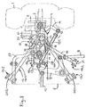
- a steerable, air-sprung Wheel and designated with 2 of this bearing wheel carrier.
- the latter is pivoted about a kingpin 3 to a kingpin 4.
- This in turn is only schematic over several handlebars on the one in the drawing indicated vehicle frame 5 articulated.
- a steering gear 6 the via a lever arm 7, a handlebar 8 connected thereto, one on this Articulated toggle lever 9 and a tie rod 10 arranged on a wheel carrier fixed Steering lever 11 acts.
- a middle tie rod 12 connects the toggle lever 9 the wheel side opposite the axle.
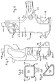
- the steering knuckle 4 is to achieve high torsional rigidity as a cast, self-profiled hollow body made of cast steel or nodular cast iron, for example realizable. Details and details of a steering knuckle cast in this way 4 can be seen from FIGS. 6 to 9. In it 4/1 denote the Outer wall and 4/2 the enclosed cavity of the steering knuckle 4. With 4/3 are cast core eyes. Alternatively, the steering knuckle can be used 4 but also as a drop-forged part with a cross-sectional profile, e.g. B. made of tempered steel. Regardless of the chipless production method its basic shape is the final shape of the axle body 4 by appropriate Machining post-processing of the blank at required locations.
- the wishbone overlaps 13 with its V-shaped legs 13/1, 13/2 in between protruding steering knuckle 4 and is with its thigh-knee area hinged to the latter at the bottom outside.
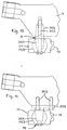
- the wishbone 13 with its thigh-knee area - like 10 and 11 show the examples - flying at one at the lower end of the steering knuckle 4 projecting bearing member 34 may be hinged. On this is discussed in more detail later.
- the wishbone 13 is inside the thigh as well as in the knee area Legs 13/1, 13/2 each have a spherical molecular spherical bearing 17/1, 17/2, 17/3 articulated on the vehicle frame 5 or steering knuckle 4.
- the two legs 13/1, 13/2 of the wishbone 13 each have an inner end a bearing eye 20/1 or 20/2.
- the two legs 13/1, 13/2 of the wishbone 13 each have an inner end a bearing eye 20/1 or 20/2.
- a maintenance-free spherical molecular bearing is about the outer claws of the two spherical bearings 17/1, 17/2.
- the wishbone 13 also has its two legs 13/1, 13/2 Bearing eye 21 with built-in maintenance-free spherical molecular bearing.
- This is in the case of the embodiment of FIGS. 1 to 9 part of a vertical extending molecular ball claw spherical plain bearing 17/3, over the outer, vertically arranged claws of the wishbones 13 'on the outside of the steering knuckle 4 is articulated.
- the latter has an outside in its lower region mouth-shaped indentation 22, into which the wishbone 13 with its bearing eye 21 partially immersed.
- Above and below the indentation 22 are on Steering knuckle 4 contact surfaces 23 for supporting the claws of the spherical plain bearing 17/3 and tapped holes 23/1 for fixing them using Given screws.
- the bearing journal is 34/1 part of a double tapered bolt with its upper tapered Bolt section 34/2 formed in a bottom end on the steering knuckle 4 Immerses the conical bore and in it with a positive and non-positive fit with a screw 34/3 is locked, which at the same time for the permanent storage of the bearing 17/3 on tapered bearing journal 34/1 is used.
- the tapered bearing journal 34/1 part of a retaining plate 34/4, which by means of screws 34/5 is attached to the lower end of the steering knuckle 4.
- the camp 17/3 is in this case clamped to the tapered journal 34/1 by means of a screw 34/6.
- Each of the two identical wishbones 14, 15 has an inner end eye 24 and an outer-end bearing eye 25, each with a transverse to the longitudinal direction of the handlebars running through hole, in each of which a twistable, cylindrical Molecular bush bearing 18 installed with its cylindrical slot bush is.
- a twistable, cylindrical Molecular bush bearing 18 installed with its cylindrical slot bush is.
- tie rod designated, the two inner-end molecular bearing slot bushings, the two tapered sleeves 26 supported thereon and the associated conical bore sections having through hole on the frame side (not shown) Bearing block penetrates and for the internal fastening of the two wishbones 14, 15 on the vehicle frame 5.
- tie rod designates the two outer molecular bearing slot bushings, the two tapered sleeves 26 supported thereon and the associated ones Through hole 27 having conical bore sections in the steering knuckle 4 penetrates and for the external fastening of the two wishbones 14, 15 on the steering knuckle 4 is used.
- the two links 14, 15 each from the outside by appropriate axial prestressing of each of the two Tie rods 28, 29 clamped to the bearing block or steering knuckle 4, wherein the axial force via the two molecular bearing slotted bushings each seated on one of the tie rods 28, 29 in such a way with high friction in the conical Bore sections pressed conical sleeves 26 is transmitted.
- Serving trailing arm 16 is arranged in a horizontal plane that is parallel extends to that receiving the wishbone 13, but close to the upper Wishbones 14, 15 moved just below (as shown) or arranged above them is.
- the trailing arm 16 can be oblique or in the horizontal plane running parallel to the longitudinal axis of the vehicle in front of or behind the axle body 4, either stretched or tensioned.
- the Trailing arm 16 at each of its two ends with a bearing eye 30 and 31, respectively a through hole extending transversely to the longitudinal direction of the handlebar, into which each a molecular bushing bearing 19/1 or 19/2 with its cylindrical slot bushing is installed.
- the links 14, 15, 16 are preferably each made by a one-piece drop-forged part realized, but can also be represented as a cast part, the Raw part is machined accordingly after removal from the necessary places is reworked.
- the above-described independent suspension is supplemented by a spring-damper device per wheel 1.
- a spring-damper device per wheel 1.
- a slightly oblique vertical standing shock absorber 35 which in the case of the example shown in FIGS. 1 to 9, the wishbone 13 protrudes, is at the top of the vehicle frame, there a (not shown) Bearing block, and at the bottom at the lower area of the steering knuckle 4 hinged on the inside.
- the latter is approximately in the amount of Indentation 22 means 36, for example a projection or bearing eyes.
- a stabilizer 37 that the lateral inclination of the Vehicle in curves and its cross wind sensitivity reduced as well Rolling behavior improved.
- Such a stabilizer 37 can be seen in a top view U-shaped, the two steering knuckle supports 4 given for each axis connect articulated to each other and via (not shown) wings or bearing blocks be hung on the vehicle frame 5.
- the connection point on the steering knuckle is given by the organ 4/6 there.
Landscapes
- Engineering & Computer Science (AREA)
- Mechanical Engineering (AREA)
- Chemical & Material Sciences (AREA)
- Combustion & Propulsion (AREA)
- Transportation (AREA)
- Vehicle Body Suspensions (AREA)
- Automobile Manufacture Line, Endless Track Vehicle, Trailer (AREA)
Description
- in Fig. 1 in perspektivischer Ansicht schräg von vorne her,
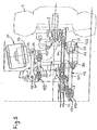
- in Fig. 2 in perspektivischer Ansicht schräg von hinten her,
- in Fig. 3 in Draufsicht,
- in Fig. 4 in Seitenansicht, und
- in Fig. 5 in Vorderansicht.
- Fig. 6
- in Vorderansicht,
- Fig. 7
- in Seitenansicht vom Rad her,
- Fig. 8
- im Schnitt entlang Schnittlinie D-D aus Fig. 6, und
- Fig. 9
- im Schnitt entlang Schnittlinie F-F aus Fig. 6.
- a)
- eines als verwindungssteifes Guß- oder Schmiedeteil ausgeführten Achsschenkelträgers 4 mit
- b)
- einer Radführung mit einem Dreieckslenker 13, zwei Querlenkern 14, 15 und einem Längslenker 16 in spezieller Anordnung, nämlich
- b1)
- der Dreieckslenker 13 ist
- b1.1)
- in einer unteren Horizontalebene angeordnet und
- b1.2)
- schenkelinnenseitig am Fahrzeugrahmen 5 sowie mit seinem Schenkelkniebereich am unteren Bereich des Achsschenkelträgers 4 angelenkt
- b1.2.1)
- über jeweils ein Gelenklager 17/1, 17/2, 17/3,
- b2)
- die beiden Querlenker 14, 15 sind
- b2.1)
- stabförmig und gleich ausgebildet,
- b2.2)
- in einer oberen Horizontalebene parallel oder leicht gepfeilt zueinander und quer zur Fahrzeuglängsachse angeordnet,
- b2.3)
- außenendig am oberen Bereich des Achsschenkelträgers 4, vorn bzw. hinten an diesem, und innenseitig am Fahrzeugrahmen 5 angelenkt
- b2.3.1)
- über jeweils ein verdrehweiches Lager 18,
- b3)
- der Längslenker 16 ist
- b3.1)
- in einer Horizontalebene sich nach vorne oder hinten erstreckend angeordnet, sowie
- b3.2)
- einenendes am Fahrzeugrahmen 5 und andernendes am oberen Bereich des Achsschenkelträgers 4 zu dessen Stabilisierung angelenkt
- b3.2.1)
- über jeweils ein verdrehweiches Lager 19/1, 19/2.
Claims (17)
- Einzelradaufhängung für ein luftgefedertes, lenkbares Rad (1) eines Omnibusses oder Lastkraftwagen, das auf einem Radträger (2) gelagert ist, der um einen Achsschenkelbolzen (3) schwenkbar an einem Achsschenkelträger (4) und dieser wiederum über mehrere Lenker geführt am Fahrzeugrahmen angelenkt ist, gekennzeichnet durch die Kombinationa) eines als verwindungssteifes Guß- oder Schmiedeteil ausgeführten Achsschenkelträgers (4) mitb) einer Radführung mit einem Dreieckslenker (13), zwei Querlenkern (14, 15) und einem Längslenker (16) in spezieller Anordnung, nämlichb1) der Dreieckslenker (13) istb1.1) in einer unteren Horizontalebene angeordnet undb1.2) schenkelinnenseitig am Fahrzeugrahmen (5) sowie mit seinem Schenkel-Kniebereich am unteren Bereich des Achsschenkelträgers (4) angelenktb1.2.1) über jeweils ein Gelenklager (17/1, 17/2, 17/3),b2) die beiden Querlenker (14, 15) sindb2.1) stabförmig und gleich ausgebildet,b2.2) in einer oberen Horizontalebene parallel oder leicht gepfeilt zueinander und quer zur Fahrzeuglängsachse angeordnet,b2.3) außenendig am oberen Bereich des Achsschenkelträgers (4), vorn bzw. hinten an diesem, und innenseitig am Fahrzeugrahmen (5) angelenktb2.3.1) über jeweils ein verdrehweiches Lager (18),b3) der Längslenker (16) istb3.1) in einer Horizontalebene sich nach vorne oder hinten erstreckend angeordnet, sowieb3.2) einenendes am Fahrzeugrahmen (5) und anderenendes am oberen Bereich des Achsschenkelträgers (4) zu dessen Stabilisierung angelenktb3.2.1) über jeweils ein verdrehweiches Lager (19/1, 19/2).
- Einzelradaufhängung nach Anspruch 1, dadurch gekennzeichnet, daß der Dreieckslenker (13) mit seinen V-förmig gespreizten Schenkeln (13/1, 13/2) den dazwischen durchragenden Achsschenkelträger (4) übergreift und an diesem unten außen mit seinem Schenkel-Kniebereich angelenkt ist.
- Einzelradaufhängung nach Anspruch 1, dadurch gekennzeichnet, daß der Dreieckslenker (13) mit seinem Schenkel-Kniebereich fliegend an einem am unteren Ende des Achsschenkelträgers (4) abragenden Lagerorgan (34; 34/1) angelenkt ist.
- Einzelradaufhängung nach einem der Ansprüche 1 bis 3, dadurch gekennzeichnet, daß der Dreieckslenker (13) schenkelinnenseitig wie auch im Kniebereich seiner beiden Schenkel (13/1, 13/2) über jeweils ein kugliges Molekular-Gelenklager (17/1, 17/2, 17/3) am Fahrzeugrahmen (5) bzw. Achsschenkelträgers (4) angelenkt ist.
- Einzelradaufhängung nach einem der vorhergehenden Ansprüche, dadurch gekennzeichnet, daß die beiden Schenkel (13/1, 13/2) des Dreieckslenkers (13) innenendig jeweils ein Lagerauge (20/1, 20/2) aufweisen, in jedes derselben als Bestandteil eines sich in der Horizontalebene erstreckenden Molekular-Kugelpratzen-Gelenklagers (17/1, 17/2) ein wartungsfreies kugliges Molekuarlager eingebaut ist, und daß über die äußeren Pratzen der beiden Gelenklager (17/1, 17/2) mit zugehörigen Schrauben der Dreieckslenker (13) innenendig am Fahrzeugrahmen (5), dort einem entsprechenden Lagerbock, angelenkt ist.
- Einzelradaufhängung nach einem der Ansprüche 1 und 2, dadurch gekennzeichnet, daß der Dreieckslenker (13) im Kniebereich seiner beiden Schenkel (13/1, 13/2) ein Lagerauge (21) aufweist, in das ein wartungsfreies kugliges Molekularlager eingebaut ist, das wiederum Bestandteil eines vertikal angeordneten Molekular-Kugelpratzen-Gelenklagers (17/3) ist, über dessen äußere, vertikale Pratzen der Dreieckslenker (13) außen am Achsschenkelträger (4) angelenkt ist.
- Einzelradaufhängung nach Anspruch 6, dadurch gekennzeichnet, daß der Achsschenkelträger (4) in seinem unteren Bereich außen eine maulförmige Einbuchtung (22) aufweist, in die der Dreieckslenker (13) mit seinem im Schenkel-kniebereich gegebenen Lagerauge (21) partiell eintaucht, und daß oberhalb und unterhalb der Einbuchtung (22) am Achsschenkelträger (4) Anschlußflächen (23) mit Gewindebohrungen (23/1) für die Abstützung und Befestigung der Pratzen des Gelenklagers (17/3) gegeben sind.
- Einzelradaufhängung nach Anspruch 3, dadurch gekennzeichnet, daß am unteren Ende des Achsschenkelträgers (4) ein vertikal nach unten abragender kegliger Lagerzapfen (34/1) befestigt ist, auf dem ein kugliges Molekularlager (17/3) mit einer entsprechenden Konusbohrung aufgesetzt und mittels einer Schraube (34/3) befestigt ist, welches Molekularlager (17/3) in das im Schenkel-Kniebereich des Dreieckslenkers (13) gegebene Lagerauge (21) eingebaut ist.
- Einzelradaufhängung nach Anspruch 1, gekennzeichnet, daß jeder der beiden Querlenker (14, 15) ein innenendiges Lagerauge (24) und ein außenendiges Lagerauge (25) mit jeweils einer sich quer zur Lenker-Längsrichtung erstrekkenden Durchgangsbohrung aufweist, in die jeweils ein zylindrisches Molekular-Buchsenlager (18) mit einer zylindrischen Schlitzbuchse eingebaut ist, daß ferner an den einander zugewandten Stirnflächen der beiden lenker-innenendigen Schlitzbuchsen und der beiden lenker-außenendigen Schlitzbuchsen jeweils Kegelhülsen (26) abgestützt sind, welche in entsprechende konische Bohrungsabschnitte eingreifen, die paarweise einander gegenüberliegend an den Enden zum einen einer Durchgangsbohrung in einem rahmenfesten Lagerbock und zum anderen einer Durchgangsbohrung (27) im oberen Bereich des Achsschenkelträgers (4) ausgebildet sind, und daß die beiden Querlenker (14, 15) innenendig und außenendig über jeweils einen Zuganker (28, 29) am Lagerbock bzw. Achsschenkelträger (4) angelenkt sind, von denen jeder jeweils die beiden innenseitigen bzw. außenseitigen Schlitzbuchsen, die beiden lenker-innen- bzw. lenker-außenseitigen Kegelhülsen (26) und die die konischen Bohrungsabschnitte aufweisende Durchgangsbohrung im Lagerbock bzw. Achsschenkelträger (4) durchdringt, wobei durch entsprechende axiale Vorspannung jedes der beiden Zuganker die axiale Kraft von dem jeweiligen Schlitzbuchsenpaar auf das zugehörige Kegelhülsenpaar übertragen wird und letztere so mit hoher Friktionskraft in den konischen Bohrungsabschnitten festgespannt sind.
- Einzelradaufhängung nach Anspruch 1, dadurch gekennzeichnet, daß der Längslenker (16) in einer Horizontalebene angeordnet ist, die sich parallel zu jener den Dreieckslenker (13) aufnehmenden erstreckt, jedoch nahe zu den oberen Querlenkern (14, 15) hingerückt, knapp unter oder über diesen angeordnet ist, und daß der Längslenker (16) sich in der Horizontalebene schräg oder parallel zur Fahrzeuglängsachse verlaufend erstreckt.
- Einzelradaufhängung nach einem der Ansprüche 1 und 10, dadurch gekennzeichnet, daß der Längslenker (16) an jedem seiner beiden Enden ein Lagerauge (30, 31) aufweist, in dessen Querdurchgangsbohrung ein Molekular-Buchsenlager (19/1 bzw. 19/2) mit einer zylindrischen Schlitzbuchse eingebaut ist, wobei über die Pratzen des einen Molekular-Buchsenlagers (19/1) die Verbindung zum oberen Bereich des Achsschenkelträgers (4) und über die Pratzen des anderen Molekular-Buchsenlagers (19/2) die Verbindung zu einem fahrzeugrahmenfesten Lagerbock hergestellt ist.
- Einzelradaufhängung nach Anspruch 1, dadurch gekennzeichnet, daß die beiden Querlenker (14, 15) und der Längslenker (16) jeweils durch ein einteiliges Gelenkschmiedeteil oder Gußteil gebildet sind, das nach dem Ausformen an den erforderlichen Stellen entsprechend spanabhebend nachbearbeitet ist.
- Einzelradaufhängung nach Anspruch 1, dadurch gekennzeichnet, daß der Achsschenkelträger (4) als gegossenes, in sich profilierter Hohlkörper, beispielsweise aus Stahlguß oder Sphäroguß ausgeführt ist, an dem nach dem Ausformen an den erforderlichen Stellen entsprechend spanabhebende Nacharbeiten vorgenommen sind.
- Einzelradaufhängung nach Anspruch 1, dadurch gekennzeichnet, daß der Achsschenkelträger (4) als in sich querschnittsmäßig profiliertes Schmiedeteil, beispielsweise aus Vergütungsstahl ausgebildet ist, an dem nach dem Ausformen an den erforderlichen Stellen entsprechend notwendige spanabhebende Nacharbeiten durchgeführt sind.
- Einzelradaufhängung nach Anspruch 1, gekennzeichnet durch deren Kombination mit einer Feder-Dämpfer-Einrichtung je Rad (1), bei der ein Luftfederbalg (32) mit seinem untenendigen Balgführungstopf (33) am oberen Ende des Achsschenkelträgers (4) und obenendig mit einer Dichtplatte am Fahrzeugrahmen (5), dort an einem Lagerbock angeschlossen ist, und bei der ein Stoßdämpfer (35) den Dreieckslenker (13) zwischen dessen Schenkeln (13/1, 13/2) durchragt und obenendig am Fahrzeugrahmen (5) sowie untenendig am unteren Bereich des Achsschenkelträgers (4) innenseitig an diesem angelenkt ist.
- Einzelradaufhängung nach den Ansprüchen 1 und 15, gekennzeichnet durch deren Kombination mit einem in Draufsicht gesehen U-förmigen Stabilisator, der die beiden je Achse gegebenen Achsschenkelträger (4) miteinander gelenkig verbindet und über Schwingen oder Lagerböcke am Fahrzeugrahmen (5) aufgehängt ist.
- Einzelradaufhängung nach Anspruch 15, gekennzeichnet, daß an der Innenseite des Achsschenkelträgers (4), etwa in Höhe der Einbuchtung (22) Mittel (36), beispielsweise ein Vorsprung oder Lageraugen, für die untere Abstützung und Anlenkung des Stoßdämpfers (35) gegeben sind.
Applications Claiming Priority (2)
| Application Number | Priority Date | Filing Date | Title |
|---|---|---|---|
| DE19619189 | 1996-05-11 | ||
| DE19619189A DE19619189A1 (de) | 1996-05-11 | 1996-05-11 | Einzelradaufhängung für ein luftgefedertes, lenkbares Rad eines Omnibusses oder Lastkraftwagen |
Publications (3)
| Publication Number | Publication Date |
|---|---|
| EP0806310A2 EP0806310A2 (de) | 1997-11-12 |
| EP0806310A3 EP0806310A3 (de) | 1999-05-12 |
| EP0806310B1 true EP0806310B1 (de) | 2001-11-28 |
Family
ID=7794143
Family Applications (1)
| Application Number | Title | Priority Date | Filing Date |
|---|---|---|---|
| EP97104006A Expired - Lifetime EP0806310B1 (de) | 1996-05-11 | 1997-03-11 | Einzelradaufhängung für ein luftgefedertes, lenkbares Rad eines Omnibusses oder Lastkraftwagens |
Country Status (5)
| Country | Link |
|---|---|
| EP (1) | EP0806310B1 (de) |
| DE (2) | DE19619189A1 (de) |
| ES (1) | ES2163675T3 (de) |
| HU (1) | HU223132B1 (de) |
| TR (1) | TR199700336A3 (de) |
Cited By (1)
| Publication number | Priority date | Publication date | Assignee | Title |
|---|---|---|---|---|
| DE102010004321A1 (de) | 2010-01-12 | 2011-07-14 | MAN Truck & Bus AG, 80995 | Nutzfahrzeug mit einer Anbindung eines Dreiecklenkers |
Families Citing this family (15)
| Publication number | Priority date | Publication date | Assignee | Title |
|---|---|---|---|---|
| AU738852C (en) * | 1997-12-12 | 2003-04-10 | Holland Neway International, Inc. | Independent front suspension |
| SE518449C2 (sv) * | 1999-10-18 | 2002-10-08 | Volvo Lastvagnar Ab | Hjulupphängning |
| DE10007192C2 (de) * | 2000-02-17 | 2002-10-24 | Benteler Werke Ag | Lenker für Kraftfahrzeuge |
| DE10061408A1 (de) * | 2000-12-09 | 2002-06-13 | Zahnradfabrik Friedrichshafen | Lenkvorrichtung für lenkbare Vorderräder |
| DE10061407A1 (de) | 2000-12-09 | 2002-06-13 | Zahnradfabrik Friedrichshafen | Einzelradaufhängung für ein gefedertes, lenkbares Rad |
| US6866295B2 (en) | 2000-12-28 | 2005-03-15 | Dana Corporation | Modular cast independent front suspension subframe |
| ITTO20020268A1 (it) * | 2002-03-26 | 2003-09-26 | Iveco Fiat | Sospensione indipendente per una ruota di un veicolo industriale. |
| US6783137B2 (en) | 2002-11-14 | 2004-08-31 | Tuthill Corporation | Steering knuckle carrier-to-suspension arm pivotal connection and method of assembling and preloading the pivotal connection |
| GB2405381A (en) * | 2003-09-01 | 2005-03-02 | Ford Global Tech Llc | Five-link vehicle suspension system |
| DE102005035913A1 (de) * | 2005-07-28 | 2007-02-08 | Zf Friedrichshafen Ag | Kraftfahrzeugfahrwerk |
| DE102006031708A1 (de) * | 2006-07-08 | 2008-01-10 | Daimlerchrysler Ag | Verfahren zur Herstellung eines Achsschenkels |
| FR2914586A1 (fr) * | 2007-04-03 | 2008-10-10 | Renault Sas | Train arriere multi-bras pour vehicule automobile |
| CN103075452B (zh) * | 2013-01-25 | 2015-12-02 | 安徽江淮汽车股份有限公司 | 一种空气悬架用导向簧总成 |
| CN105059074B (zh) * | 2015-09-08 | 2018-02-02 | 北京航天发射技术研究所 | 具有过载保护功能的悬架限位器、悬架系统和车辆 |
| CN113635722A (zh) * | 2021-08-16 | 2021-11-12 | 西南交通大学 | 一种适用于轮毂电机驱动虚拟轨道列车的半主动悬架系统 |
Family Cites Families (12)
| Publication number | Priority date | Publication date | Assignee | Title |
|---|---|---|---|---|
| US2934352A (en) * | 1956-11-19 | 1960-04-26 | Gen Motors Corp | Vehicle fluid suspension |
| FR1232152A (fr) * | 1958-08-12 | 1960-10-06 | Guy Motors Ltd | Suspension pour véhicules à roues directrices indépendantes |
| AT295337B (de) * | 1968-08-20 | 1971-12-27 | Bayerische Motoren Werke Ag | Unabhängige Aufhängung der gelenkten Räder von Kraftfahrzeugen, insbesondere Personenkraftwagen |
| BE789857A (fr) * | 1971-10-13 | 1973-02-01 | Carrozzeria | Suspension pneumatique avant a roues independantes pour des autobus et vehicules industriels |
| DE2624704B1 (de) * | 1976-06-02 | 1978-04-27 | Georg Fischer Ag, Schaffhausen (Schweiz) | Einteiliges, als Gußteil ausgebildetes Schwenklager für ein gelenktes Fahrzeugrad |
| DE2918605A1 (de) * | 1979-05-09 | 1980-11-13 | Daimler Benz Ag | Einzelradaufhaengung mittels uebereinander angeordneter fuehrungslenker |
| DE3345952A1 (de) * | 1983-12-20 | 1985-06-27 | Fa. Gotthard Drögmöller, 7100 Heilbronn | Drehlagerverbindung zwischen federtraeger und querlenker bei einer kraftfahrzeug-vorderachsaufhaengung |
| JPS6121802A (ja) * | 1984-07-10 | 1986-01-30 | Nissan Motor Co Ltd | 車両用懸架装置 |
| DE3718137A1 (de) * | 1987-05-29 | 1988-12-15 | Man Nutzfahrzeuge Gmbh | Einzelradaufhaengung fuer ein lenkbares rad an einem nutzfahrzeug |
| DE4017210C1 (de) * | 1990-05-29 | 1991-10-31 | Mercedes-Benz Aktiengesellschaft, 7000 Stuttgart, De | |
| FR2675431B1 (fr) * | 1991-04-16 | 1993-07-16 | Renault | Dispositif de suspension de vehicule a jambe articulee. |
| FR2707926B1 (fr) * | 1993-06-29 | 1995-10-06 | Peugeot | Dispositif de suspension perfectionné pour une roue avant de véhicule automobile. |
-
1996
- 1996-05-11 DE DE19619189A patent/DE19619189A1/de not_active Withdrawn
-
1997
- 1997-03-11 DE DE59705492T patent/DE59705492D1/de not_active Expired - Lifetime
- 1997-03-11 EP EP97104006A patent/EP0806310B1/de not_active Expired - Lifetime
- 1997-03-11 ES ES97104006T patent/ES2163675T3/es not_active Expired - Lifetime
- 1997-03-21 HU HU9700626A patent/HU223132B1/hu active IP Right Grant
- 1997-05-01 TR TR97/00336A patent/TR199700336A3/tr unknown
Cited By (2)
| Publication number | Priority date | Publication date | Assignee | Title |
|---|---|---|---|---|
| DE102010004321A1 (de) | 2010-01-12 | 2011-07-14 | MAN Truck & Bus AG, 80995 | Nutzfahrzeug mit einer Anbindung eines Dreiecklenkers |
| EP2351656A1 (de) | 2010-01-12 | 2011-08-03 | MAN Truck & Bus AG | Nutzfahrzeug mit einer Anbindung eines Dreieckslenkers |
Also Published As
| Publication number | Publication date |
|---|---|
| ES2163675T3 (es) | 2002-02-01 |
| TR199700336A2 (xx) | 1998-10-21 |
| DE59705492D1 (de) | 2002-01-10 |
| EP0806310A2 (de) | 1997-11-12 |
| HU9700626D0 (en) | 1997-05-28 |
| HUP9700626A3 (en) | 2000-02-28 |
| HU223132B1 (hu) | 2004-03-29 |
| HUP9700626A2 (hu) | 1998-11-30 |
| TR199700336A3 (tr) | 1998-10-21 |
| DE19619189A1 (de) | 1997-11-13 |
| EP0806310A3 (de) | 1999-05-12 |
Similar Documents
| Publication | Publication Date | Title |
|---|---|---|
| DE102004058698B3 (de) | Radaufhängung mit Federverstellung für Kraftfahrzeuge | |
| DE60125410T2 (de) | Fahrzeugaufhängungssystem | |
| EP0656270B1 (de) | Radaufhängung | |
| DE10053411B4 (de) | Fahrzeugachse | |
| EP0141092B1 (de) | Unabhängige Radaufhängung für Kraftfahrzeuge | |
| EP0806310B1 (de) | Einzelradaufhängung für ein luftgefedertes, lenkbares Rad eines Omnibusses oder Lastkraftwagens | |
| DE19743736B4 (de) | Vorderradaufhängung | |
| DE3740310C2 (de) | ||
| EP2514616B1 (de) | Radaufhängung für eine Achse eines Kraftfahrzeuges | |
| DE10133424A1 (de) | Hinterachse eines Personenkraftwagens mit fünf einzelnen Lenkern | |
| DE102016220786B4 (de) | Hinterradaufhängung für Kraftfahrzeuge | |
| DE102013210338A1 (de) | Mehrlenkerhinterachse für ein Fahrzeug | |
| DE10032961B4 (de) | Drehstabfeder | |
| EP1080953A1 (de) | Radaufhängung für Kraftfahrzeuge mit einer radführenden Blattfeder | |
| EP1900554A1 (de) | Einzelradaufhängung vom Doppelquerlenker-Typ | |
| EP3452310B1 (de) | Einzelradaufhängung eines fahrzeugs mit einem radführenden blattfederelement aus einem faserverbund-werkstoff | |
| WO2020038855A1 (de) | Hinterachse eines fahrzeuges | |
| EP0873891A2 (de) | Einzelradaufhängung für gelenkte Räder von Kraftfahrzeugen, insbesondere Personenkraftwagen | |
| DE60306730T2 (de) | Lenkeinrichtung für die Trage-Einrichtung der Hinterradnabe in Motorfahrzeugen | |
| WO2004069567A1 (de) | Radaufhängung für kraftfahrzeuge | |
| DE10061407A1 (de) | Einzelradaufhängung für ein gefedertes, lenkbares Rad | |
| DE1959844A1 (de) | Hinterachsaufhaengung | |
| EP1110848B1 (de) | Längslenkerbock in Nutzfahrzeugen | |
| DE102017211277B4 (de) | Radaufhängung für ein Kraftfahrzeug | |
| DE4008465A1 (de) | Vorspannbares lager |
Legal Events
| Date | Code | Title | Description |
|---|---|---|---|
| PUAI | Public reference made under article 153(3) epc to a published international application that has entered the european phase |
Free format text: ORIGINAL CODE: 0009012 |
|
| AK | Designated contracting states |
Kind code of ref document: A2 Designated state(s): BE DE ES FR IT NL |
|
| PUAL | Search report despatched |
Free format text: ORIGINAL CODE: 0009013 |
|
| AK | Designated contracting states |
Kind code of ref document: A3 Designated state(s): BE DE ES FR IT NL |
|
| 17P | Request for examination filed |
Effective date: 19990616 |
|
| GRAG | Despatch of communication of intention to grant |
Free format text: ORIGINAL CODE: EPIDOS AGRA |
|
| 17Q | First examination report despatched |
Effective date: 20010302 |
|
| GRAG | Despatch of communication of intention to grant |
Free format text: ORIGINAL CODE: EPIDOS AGRA |
|
| GRAH | Despatch of communication of intention to grant a patent |
Free format text: ORIGINAL CODE: EPIDOS IGRA |
|
| GRAH | Despatch of communication of intention to grant a patent |
Free format text: ORIGINAL CODE: EPIDOS IGRA |
|
| ITF | It: translation for a ep patent filed | ||
| GRAA | (expected) grant |
Free format text: ORIGINAL CODE: 0009210 |
|
| AK | Designated contracting states |
Kind code of ref document: B1 Designated state(s): BE DE ES FR IT NL |
|
| REF | Corresponds to: |
Ref document number: 59705492 Country of ref document: DE Date of ref document: 20020110 |
|
| REG | Reference to a national code |
Ref country code: ES Ref legal event code: FG2A Ref document number: 2163675 Country of ref document: ES Kind code of ref document: T3 |
|
| ET | Fr: translation filed | ||
| PLBE | No opposition filed within time limit |
Free format text: ORIGINAL CODE: 0009261 |
|
| STAA | Information on the status of an ep patent application or granted ep patent |
Free format text: STATUS: NO OPPOSITION FILED WITHIN TIME LIMIT |
|
| 26N | No opposition filed | ||
| REG | Reference to a national code |
Ref country code: NL Ref legal event code: TD Effective date: 20110420 |
|
| REG | Reference to a national code |
Ref country code: FR Ref legal event code: CD |
|
| REG | Reference to a national code |
Ref country code: ES Ref legal event code: PC2A Owner name: "MAN TRUCK & Effective date: 20110620 Ref country code: ES Ref legal event code: PC2A Owner name: MAN TRUCK & BUS AG Effective date: 20110620 |
|
| REG | Reference to a national code |
Ref country code: DE Ref legal event code: R081 Ref document number: 59705492 Country of ref document: DE Owner name: MAN TRUCK & BUS AG, DE Free format text: FORMER OWNER: MAN NUTZFAHRZEUGE AG, 80995 MUENCHEN, DE Effective date: 20110518 |
|
| REG | Reference to a national code |
Ref country code: FR Ref legal event code: PLFP Year of fee payment: 20 |
|
| PGFP | Annual fee paid to national office [announced via postgrant information from national office to epo] |
Ref country code: NL Payment date: 20160324 Year of fee payment: 20 |
|
| PGFP | Annual fee paid to national office [announced via postgrant information from national office to epo] |
Ref country code: FR Payment date: 20160331 Year of fee payment: 20 Ref country code: BE Payment date: 20160324 Year of fee payment: 20 |
|
| PGFP | Annual fee paid to national office [announced via postgrant information from national office to epo] |
Ref country code: DE Payment date: 20160531 Year of fee payment: 20 Ref country code: ES Payment date: 20160422 Year of fee payment: 20 |
|
| PG25 | Lapsed in a contracting state [announced via postgrant information from national office to epo] |
Ref country code: IT Free format text: LAPSE BECAUSE OF NON-PAYMENT OF DUE FEES Effective date: 20160311 |
|
| REG | Reference to a national code |
Ref country code: DE Ref legal event code: R071 Ref document number: 59705492 Country of ref document: DE |
|
| REG | Reference to a national code |
Ref country code: NL Ref legal event code: MK Effective date: 20170310 |
|
| PG25 | Lapsed in a contracting state [announced via postgrant information from national office to epo] |
Ref country code: IT Free format text: LAPSE BECAUSE OF NON-PAYMENT OF DUE FEES Effective date: 20160311 |
|
| PGFP | Annual fee paid to national office [announced via postgrant information from national office to epo] |
Ref country code: IT Payment date: 20160325 Year of fee payment: 20 |
|
| PGRI | Patent reinstated in contracting state [announced from national office to epo] |
Ref country code: IT Effective date: 20170710 |
|
| REG | Reference to a national code |
Ref country code: ES Ref legal event code: FD2A Effective date: 20180508 |
|
| PG25 | Lapsed in a contracting state [announced via postgrant information from national office to epo] |
Ref country code: ES Free format text: LAPSE BECAUSE OF EXPIRATION OF PROTECTION Effective date: 20170312 |