EP0806310B1 - Independent suspension for a steered air suspended wheel of a bus or lorry - Google Patents
Independent suspension for a steered air suspended wheel of a bus or lorry Download PDFInfo
- Publication number
- EP0806310B1 EP0806310B1 EP97104006A EP97104006A EP0806310B1 EP 0806310 B1 EP0806310 B1 EP 0806310B1 EP 97104006 A EP97104006 A EP 97104006A EP 97104006 A EP97104006 A EP 97104006A EP 0806310 B1 EP0806310 B1 EP 0806310B1
- Authority
- EP
- European Patent Office
- Prior art keywords
- bearing
- steering
- arm
- wheel suspension
- suspension according
- Prior art date
- Legal status (The legal status is an assumption and is not a legal conclusion. Google has not performed a legal analysis and makes no representation as to the accuracy of the status listed.)
- Expired - Lifetime
Links
Images


Classifications
-
- B—PERFORMING OPERATIONS; TRANSPORTING
- B62—LAND VEHICLES FOR TRAVELLING OTHERWISE THAN ON RAILS
- B62D—MOTOR VEHICLES; TRAILERS
- B62D7/00—Steering linkage; Stub axles or their mountings
- B62D7/18—Steering knuckles; King pins
-
- B—PERFORMING OPERATIONS; TRANSPORTING
- B60—VEHICLES IN GENERAL
- B60G—VEHICLE SUSPENSION ARRANGEMENTS
- B60G11/00—Resilient suspensions characterised by arrangement, location or kind of springs
- B60G11/26—Resilient suspensions characterised by arrangement, location or kind of springs having fluid springs only, e.g. hydropneumatic springs
- B60G11/27—Resilient suspensions characterised by arrangement, location or kind of springs having fluid springs only, e.g. hydropneumatic springs wherein the fluid is a gas
-
- B—PERFORMING OPERATIONS; TRANSPORTING
- B60—VEHICLES IN GENERAL
- B60G—VEHICLE SUSPENSION ARRANGEMENTS
- B60G3/00—Resilient suspensions for a single wheel
- B60G3/18—Resilient suspensions for a single wheel with two or more pivoted arms, e.g. parallelogram
- B60G3/20—Resilient suspensions for a single wheel with two or more pivoted arms, e.g. parallelogram all arms being rigid
-
- B—PERFORMING OPERATIONS; TRANSPORTING
- B60—VEHICLES IN GENERAL
- B60G—VEHICLE SUSPENSION ARRANGEMENTS
- B60G7/00—Pivoted suspension arms; Accessories thereof
- B60G7/008—Attaching arms to unsprung part of vehicle
-
- B—PERFORMING OPERATIONS; TRANSPORTING
- B60—VEHICLES IN GENERAL
- B60G—VEHICLE SUSPENSION ARRANGEMENTS
- B60G2200/00—Indexing codes relating to suspension types
- B60G2200/10—Independent suspensions
- B60G2200/14—Independent suspensions with lateral arms
- B60G2200/144—Independent suspensions with lateral arms with two lateral arms forming a parallelogram
-
- B—PERFORMING OPERATIONS; TRANSPORTING
- B60—VEHICLES IN GENERAL
- B60G—VEHICLE SUSPENSION ARRANGEMENTS
- B60G2200/00—Indexing codes relating to suspension types
- B60G2200/10—Independent suspensions
- B60G2200/18—Multilink suspensions, e.g. elastokinematic arrangements
-
- B—PERFORMING OPERATIONS; TRANSPORTING
- B60—VEHICLES IN GENERAL
- B60G—VEHICLE SUSPENSION ARRANGEMENTS
- B60G2200/00—Indexing codes relating to suspension types
- B60G2200/40—Indexing codes relating to the wheels in the suspensions
- B60G2200/44—Indexing codes relating to the wheels in the suspensions steerable
-
- B—PERFORMING OPERATIONS; TRANSPORTING
- B60—VEHICLES IN GENERAL
- B60G—VEHICLE SUSPENSION ARRANGEMENTS
- B60G2202/00—Indexing codes relating to the type of spring, damper or actuator
- B60G2202/10—Type of spring
- B60G2202/13—Torsion spring
- B60G2202/135—Stabiliser bar and/or tube
-
- B—PERFORMING OPERATIONS; TRANSPORTING
- B60—VEHICLES IN GENERAL
- B60G—VEHICLE SUSPENSION ARRANGEMENTS
- B60G2202/00—Indexing codes relating to the type of spring, damper or actuator
- B60G2202/10—Type of spring
- B60G2202/15—Fluid spring
- B60G2202/152—Pneumatic spring
-
- B—PERFORMING OPERATIONS; TRANSPORTING
- B60—VEHICLES IN GENERAL
- B60G—VEHICLE SUSPENSION ARRANGEMENTS
- B60G2204/00—Indexing codes related to suspensions per se or to auxiliary parts
- B60G2204/10—Mounting of suspension elements
- B60G2204/12—Mounting of springs or dampers
- B60G2204/126—Mounting of pneumatic springs
-
- B—PERFORMING OPERATIONS; TRANSPORTING
- B60—VEHICLES IN GENERAL
- B60G—VEHICLE SUSPENSION ARRANGEMENTS
- B60G2204/00—Indexing codes related to suspensions per se or to auxiliary parts
- B60G2204/10—Mounting of suspension elements
- B60G2204/14—Mounting of suspension arms
- B60G2204/148—Mounting of suspension arms on the unsprung part of the vehicle, e.g. wheel knuckle or rigid axle
- B60G2204/1484—Mounting of suspension arms on the unsprung part of the vehicle, e.g. wheel knuckle or rigid axle on an intermediate upright strut upon which the stub axle is pivoted
-
- B—PERFORMING OPERATIONS; TRANSPORTING
- B60—VEHICLES IN GENERAL
- B60G—VEHICLE SUSPENSION ARRANGEMENTS
- B60G2206/00—Indexing codes related to the manufacturing of suspensions: constructional features, the materials used, procedures or tools
- B60G2206/01—Constructional features of suspension elements, e.g. arms, dampers, springs
- B60G2206/10—Constructional features of arms
- B60G2206/121—Constructional features of arms the arm having an H or X-shape
-
- B—PERFORMING OPERATIONS; TRANSPORTING
- B60—VEHICLES IN GENERAL
- B60G—VEHICLE SUSPENSION ARRANGEMENTS
- B60G2206/00—Indexing codes related to the manufacturing of suspensions: constructional features, the materials used, procedures or tools
- B60G2206/01—Constructional features of suspension elements, e.g. arms, dampers, springs
- B60G2206/50—Constructional features of wheel supports or knuckles, e.g. steering knuckles, spindle attachments
-
- B—PERFORMING OPERATIONS; TRANSPORTING
- B60—VEHICLES IN GENERAL
- B60G—VEHICLE SUSPENSION ARRANGEMENTS
- B60G2300/00—Indexing codes relating to the type of vehicle
- B60G2300/02—Trucks; Load vehicles
-
- B—PERFORMING OPERATIONS; TRANSPORTING
- B60—VEHICLES IN GENERAL
- B60G—VEHICLE SUSPENSION ARRANGEMENTS
- B60G2300/00—Indexing codes relating to the type of vehicle
- B60G2300/14—Buses
-
- B—PERFORMING OPERATIONS; TRANSPORTING
- B60—VEHICLES IN GENERAL
- B60G—VEHICLE SUSPENSION ARRANGEMENTS
- B60G2300/00—Indexing codes relating to the type of vehicle
- B60G2300/38—Low or lowerable bed vehicles
Definitions
- the invention relates to an independent wheel suspension for an air-sprung, steerable wheel an omnibus or truck with features in the preamble of the claim 1 Art.
- a suspension is in FR 1 232 152 A. disclosed.
- JP 61 021 802, EP 0 182 480 A2 and EP 0 242 883 B1 there the version according to FIG. 14, is referred to.
- These documents each disclose independent wheel suspensions for unguided wheels from Motor vehicles.
- a suspension for one unguided wheel is practically not usable for a steerable wheel because in the latter in addition, a steering knuckle is necessary and also the linkage and the lever position of the steering mechanism and its range of motion are taken into account Need to become.
- the independent wheel suspension according to the invention is for each steerable wheel of a bus or trucks applicable.
- the inventive method can be used with particular advantage Implement independent wheel suspension on the front axle of a coach, because there the advantages of the same come in a particularly strong way Validity.
- the independent wheel suspension according to the invention creates in or on such a coach for the steered front wheels with a very space-saving design Maximum thanks to the special elesto-kinematic design of the handlebar bearings in driving comfort and also meets requirements for high axle load capacity and Maximum possible steering angle of 56 ° for the inside of the curve Wheel.
- the independent wheel suspension according to the invention ensures direct, precise and smooth steering of the wheels is comparatively easy and quick to install and very easy to service.
- the independent wheel suspension according to the invention also allows a comparative deep floor level with a large central aisle width between the Wheel arches.
- the serviceability of the independent wheel suspension according to the invention results, among other things, from the fact that the lower wishbone is supported maintenance-free spherical molecular bearings and for mounting the upper wishbones and of the trailing link maintenance-free, particularly torsionally soft cylindrical molecular bearings be used.
- the upper handlebar system interacts completely neutral with the lower wishbone for spring movements of a wheel and squeeze-free. Component tolerances, for example in the lengths of the handlebars, are practically insignificant and thus do the same with conventional ones Solutions often necessary compensation measures during assembly superfluous.
- a steerable, air-sprung Wheel and designated with 2 of this bearing wheel carrier.
- the latter is pivoted about a kingpin 3 to a kingpin 4.
- This in turn is only schematic over several handlebars on the one in the drawing indicated vehicle frame 5 articulated.
- a steering gear 6 the via a lever arm 7, a handlebar 8 connected thereto, one on this Articulated toggle lever 9 and a tie rod 10 arranged on a wheel carrier fixed Steering lever 11 acts.
- a middle tie rod 12 connects the toggle lever 9 the wheel side opposite the axle.
- the steering knuckle 4 is to achieve high torsional rigidity as a cast, self-profiled hollow body made of cast steel or nodular cast iron, for example realizable. Details and details of a steering knuckle cast in this way 4 can be seen from FIGS. 6 to 9. In it 4/1 denote the Outer wall and 4/2 the enclosed cavity of the steering knuckle 4. With 4/3 are cast core eyes. Alternatively, the steering knuckle can be used 4 but also as a drop-forged part with a cross-sectional profile, e.g. B. made of tempered steel. Regardless of the chipless production method its basic shape is the final shape of the axle body 4 by appropriate Machining post-processing of the blank at required locations.
- the wishbone overlaps 13 with its V-shaped legs 13/1, 13/2 in between protruding steering knuckle 4 and is with its thigh-knee area hinged to the latter at the bottom outside.
- the wishbone 13 with its thigh-knee area - like 10 and 11 show the examples - flying at one at the lower end of the steering knuckle 4 projecting bearing member 34 may be hinged. On this is discussed in more detail later.
- the wishbone 13 is inside the thigh as well as in the knee area Legs 13/1, 13/2 each have a spherical molecular spherical bearing 17/1, 17/2, 17/3 articulated on the vehicle frame 5 or steering knuckle 4.
- the two legs 13/1, 13/2 of the wishbone 13 each have an inner end a bearing eye 20/1 or 20/2.
- the two legs 13/1, 13/2 of the wishbone 13 each have an inner end a bearing eye 20/1 or 20/2.
- a maintenance-free spherical molecular bearing is about the outer claws of the two spherical bearings 17/1, 17/2.
- the wishbone 13 also has its two legs 13/1, 13/2 Bearing eye 21 with built-in maintenance-free spherical molecular bearing.
- This is in the case of the embodiment of FIGS. 1 to 9 part of a vertical extending molecular ball claw spherical plain bearing 17/3, over the outer, vertically arranged claws of the wishbones 13 'on the outside of the steering knuckle 4 is articulated.
- the latter has an outside in its lower region mouth-shaped indentation 22, into which the wishbone 13 with its bearing eye 21 partially immersed.
- Above and below the indentation 22 are on Steering knuckle 4 contact surfaces 23 for supporting the claws of the spherical plain bearing 17/3 and tapped holes 23/1 for fixing them using Given screws.
- the bearing journal is 34/1 part of a double tapered bolt with its upper tapered Bolt section 34/2 formed in a bottom end on the steering knuckle 4 Immerses the conical bore and in it with a positive and non-positive fit with a screw 34/3 is locked, which at the same time for the permanent storage of the bearing 17/3 on tapered bearing journal 34/1 is used.
- the tapered bearing journal 34/1 part of a retaining plate 34/4, which by means of screws 34/5 is attached to the lower end of the steering knuckle 4.
- the camp 17/3 is in this case clamped to the tapered journal 34/1 by means of a screw 34/6.
- Each of the two identical wishbones 14, 15 has an inner end eye 24 and an outer-end bearing eye 25, each with a transverse to the longitudinal direction of the handlebars running through hole, in each of which a twistable, cylindrical Molecular bush bearing 18 installed with its cylindrical slot bush is.
- a twistable, cylindrical Molecular bush bearing 18 installed with its cylindrical slot bush is.
- tie rod designated, the two inner-end molecular bearing slot bushings, the two tapered sleeves 26 supported thereon and the associated conical bore sections having through hole on the frame side (not shown) Bearing block penetrates and for the internal fastening of the two wishbones 14, 15 on the vehicle frame 5.
- tie rod designates the two outer molecular bearing slot bushings, the two tapered sleeves 26 supported thereon and the associated ones Through hole 27 having conical bore sections in the steering knuckle 4 penetrates and for the external fastening of the two wishbones 14, 15 on the steering knuckle 4 is used.
- the two links 14, 15 each from the outside by appropriate axial prestressing of each of the two Tie rods 28, 29 clamped to the bearing block or steering knuckle 4, wherein the axial force via the two molecular bearing slotted bushings each seated on one of the tie rods 28, 29 in such a way with high friction in the conical Bore sections pressed conical sleeves 26 is transmitted.
- Serving trailing arm 16 is arranged in a horizontal plane that is parallel extends to that receiving the wishbone 13, but close to the upper Wishbones 14, 15 moved just below (as shown) or arranged above them is.
- the trailing arm 16 can be oblique or in the horizontal plane running parallel to the longitudinal axis of the vehicle in front of or behind the axle body 4, either stretched or tensioned.
- the Trailing arm 16 at each of its two ends with a bearing eye 30 and 31, respectively a through hole extending transversely to the longitudinal direction of the handlebar, into which each a molecular bushing bearing 19/1 or 19/2 with its cylindrical slot bushing is installed.
- the links 14, 15, 16 are preferably each made by a one-piece drop-forged part realized, but can also be represented as a cast part, the Raw part is machined accordingly after removal from the necessary places is reworked.
- the above-described independent suspension is supplemented by a spring-damper device per wheel 1.
- a spring-damper device per wheel 1.
- a slightly oblique vertical standing shock absorber 35 which in the case of the example shown in FIGS. 1 to 9, the wishbone 13 protrudes, is at the top of the vehicle frame, there a (not shown) Bearing block, and at the bottom at the lower area of the steering knuckle 4 hinged on the inside.
- the latter is approximately in the amount of Indentation 22 means 36, for example a projection or bearing eyes.
- a stabilizer 37 that the lateral inclination of the Vehicle in curves and its cross wind sensitivity reduced as well Rolling behavior improved.
- Such a stabilizer 37 can be seen in a top view U-shaped, the two steering knuckle supports 4 given for each axis connect articulated to each other and via (not shown) wings or bearing blocks be hung on the vehicle frame 5.
- the connection point on the steering knuckle is given by the organ 4/6 there.
Landscapes
- Engineering & Computer Science (AREA)
- Mechanical Engineering (AREA)
- Chemical & Material Sciences (AREA)
- Combustion & Propulsion (AREA)
- Transportation (AREA)
- Vehicle Body Suspensions (AREA)
- Automobile Manufacture Line, Endless Track Vehicle, Trailer (AREA)
Description
Die Erfindung betrifft eine Einzelradaufhängung für ein luftgefedertes, lenkbares Rad eines Omnibusses oder Lastkraftwagen mit Merkmalen der im Oberbegriff des Anspruches 1 angegebenen Art. Eine solche Radaufhängung ist in FR 1 232 152 A offenbart.The invention relates to an independent wheel suspension for an air-sprung, steerable wheel an omnibus or truck with features in the preamble of the claim 1 Art. Such a suspension is in FR 1 232 152 A. disclosed.
Weiterhin geht aus der Einführungsschrift der Mercedes-Benz AG zu ihrem Omnibus des Typs O 404 für die Vorderachse eine Einzelradaufhängung hervor, bestehend aus einem oberen Dreieckslenker und einem unteren Dreieckslenker sowie aus einer über einen Hebel gelagerten Momentenstrebe, über welche Lenker der Achsschenkelträger mit dem Fahrgestellrahmen des Busses verbunden ist. Dabei ragen die beiden unteren Dreieckslenker der beiden Vorderräder ebenso wie die zugehörigen Momentenstreben weit bis nahe zur Fahrzeugmitte herein, was selbstredend einen relativ hoch darüber bauenden Fußboden bedeutet. Diese bekannte Einzelradaufhängung mag zwar ein komfortables Fahren des Busses gewährleisten, schränkt aber wegen ihrer sehr raumverzehrenden Bauweise den für andere Aggregate oder Fahrzeugteile noch verfügbaren bzw. nutzbaren Raum erheblich ein.Furthermore, the introductory text from Mercedes-Benz AG goes to their omnibus of the type O 404 for the front axle, an independent suspension consisting of an upper wishbone and a lower wishbone and one Torque strut mounted via a lever, via which handlebars the steering knuckle is connected to the chassis frame of the bus. The protrude two lower wishbones of the two front wheels as well as the associated ones Moments strive far into the middle of the vehicle, which of course makes you relatively high above floor means. This well-known independent suspension may ensure comfortable driving of the bus, limits but because of their very space-consuming construction that for other units or Vehicle parts still available or usable space significantly.
Desweiteren sei der Vollständigkeit wegen auch noch auf die JP 61 021 802, die EP 0 182 480 A2 und die EP 0 242 883 B1, dort die Version gemäß Fig. 14, verwiesen. Diese Dokumente offenbaren jeweils Einzelradaufhängungen für ungelenkte Räder von Kraftfahrzeugen. Für den Fachmann ist jedoch klar, daß eine Aufhängung für ein ungelenktes Rad praktisch nicht für ein lenkbares Rad verwendbar ist, weil bei letzterem zusätzlich ein Achsschenkelträger notwendig ist und außerdem das Gestänge und die Hebelage des Lenkmechanismus sowie dessen Bewegungsbereiche berücksichtigt werden müssen. Furthermore, for completeness, JP 61 021 802, EP 0 182 480 A2 and EP 0 242 883 B1, there the version according to FIG. 14, is referred to. These documents each disclose independent wheel suspensions for unguided wheels from Motor vehicles. However, it is clear to the person skilled in the art that a suspension for one unguided wheel is practically not usable for a steerable wheel because in the latter in addition, a steering knuckle is necessary and also the linkage and the lever position of the steering mechanism and its range of motion are taken into account Need to become.
Es ist daher Aufgabe der Erfindung, eine Einzelradaufhängung für ein lenkbares, luftgefedertes Rad eines Omnibusses oder Lastkraftwagen zu schaffen, die auf extrem platzsparende Bauweise ausgelegt ist, trotzdem ein Höchstmaß an Fahrkomfort garantiert und einen sehr hohen Radeinschlagwinkel zuläßt.It is therefore an object of the invention to provide an independent wheel suspension for a steerable air-sprung wheel of a bus or truck to create extreme space-saving design is designed, yet a maximum of driving comfort guaranteed and allows a very high steering angle.
Diese Aufgabe ist erfindungsgemäß durch eine Einzelradaufhängung gelöst, die sich durch eine Kombination von Merkmalen, wie im Kennzeichen des Anspruches 1 angegeben, kennzeichnet.This object is achieved by an independent suspension, which by a combination of features as indicated in the characterizing part of claim 1, indicates.
Vorteilhafte Ausgestaltungen und Weiterbildungen dieser Lösung sind in den Unteransprüchen gekennzeichnet.Advantageous refinements and developments of this solution are in the subclaims characterized.
Die erfindungsgemäße Einzelradaufhängung ist für jedes lenkbare Rad eines Omnibusses oder Lastkraftwagen anwendbar. Mit besonderem Vorteil läßt sich die erfindungsgemäße Einzelradaufhängung an der Vorderachse eines Reisebusses realisieren, denn dort kommen die Vorteile derselben in besonders starker Weise zur Geltung. In bzw. an einem solchen Reisebus schafft die erfindungsgemäße Einzelradaufhängung für die gelenkten Vorderräder bei sehr platzsparender Bauweise aufgrund spezieller elesto-kinematischer Auslegung der Lenkerlager ein Höchstmaß an Fahrkomfort und erfüllt auch Forderungen nach hoher Achstragfähigkeit und größtmöglichem Radeinschlagwinkel von zum Beispiel 56° für das kurveninnere Rad. Außerdem gewährleistet die erfindungsgemäße Einzelradaufhängung eine direkte, zielgenaue und leichtgängige Lenkung der Räder, ist vergleichsweise einfach und schnell montierbar sowie sehr servicefreundlich. In Verbindung mit einem Reisebus erlaubt die erfindungsgemäße Einzelradaufhängung außerdem eine vergleichsweise tiefliegende Fußbodenebene mit großer Mittelgangbreite zwischen den Radkästen. Die Servicefreundlichkeit der erfindungsgemäßen Einzelradaufhängung resultiert unter anderem daraus, daß zur Lagerung des unteren Dreieckslenkers wartungsfreie kuglige Molekularlager und zur Lagerung der oberen Querlenker und des Längslenkers wartungsfreie, besonders verdrehweiche zylindrische Molekularlager verwendet werden. Das obere Lenkersystem verhält sich in Zusammenwirkung mit dem unteren Dreieckslenker bei Federbewegungen eines Rades völlig neutral und verzwängungsfrei. Bauteiltoleranzen, zum Beispiel in den Längen der Lenker, sind praktisch bedeutungslos und machen somit auch die ansonsten bei herkömmlichen Lösungen oftmals notwendigen Ausgleichsmaßnahmen bei der Montage überflüssig. Die Verwendung von relativ kleinen, radial hochbelastbaren und präzisen Molekular-Zylinderlagern zur Anlenkung der oberen Querlenker und des Längslenkers wird ermöglicht durch den großen Wirkabstand zwischen unterem und oberem Querlenkersystem. Aufgrund einer gezielten elasto-kinematischen Auslegung der gesamten Radführung mit definierten Eigenlenk-Eigenschaften wird eine hohe Fahrstabilität und Fahrsicherheit erreicht.The independent wheel suspension according to the invention is for each steerable wheel of a bus or trucks applicable. The inventive method can be used with particular advantage Implement independent wheel suspension on the front axle of a coach, because there the advantages of the same come in a particularly strong way Validity. The independent wheel suspension according to the invention creates in or on such a coach for the steered front wheels with a very space-saving design Maximum thanks to the special elesto-kinematic design of the handlebar bearings in driving comfort and also meets requirements for high axle load capacity and Maximum possible steering angle of 56 ° for the inside of the curve Wheel. In addition, the independent wheel suspension according to the invention ensures direct, precise and smooth steering of the wheels is comparatively easy and quick to install and very easy to service. In connection with a coach the independent wheel suspension according to the invention also allows a comparative deep floor level with a large central aisle width between the Wheel arches. The serviceability of the independent wheel suspension according to the invention results, among other things, from the fact that the lower wishbone is supported maintenance-free spherical molecular bearings and for mounting the upper wishbones and of the trailing link maintenance-free, particularly torsionally soft cylindrical molecular bearings be used. The upper handlebar system interacts completely neutral with the lower wishbone for spring movements of a wheel and squeeze-free. Component tolerances, for example in the lengths of the handlebars, are practically insignificant and thus do the same with conventional ones Solutions often necessary compensation measures during assembly superfluous. The use of relatively small, radially heavy-duty and precise Molecular cylinder bearings for the articulation of the upper wishbones and the trailing arms is made possible by the large effective distance between the lower and upper Wishbone system. Due to a targeted elasto-kinematic design of the overall wheel guidance with defined self-steering properties is high Driving stability and driving safety achieved.
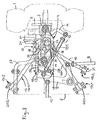
Nachstehend ist die erfindungsgemäße Einzelradaufhängung anhand mehrerer in der Zeichnung dargestellter Ausführungsbeispiele noch näher erläutert. Dabei ist die, hier für einen Reisebus als Teil der Vorderachse konzipierte Einzelradaufhängung gemäß der ersten Ausführungsform gezeigt
- in Fig. 1 in perspektivischer Ansicht schräg von vorne her,
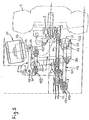
- in Fig. 2 in perspektivischer Ansicht schräg von hinten her,
- in Fig. 3 in Draufsicht,
- in Fig. 4 in Seitenansicht, und
- in Fig. 5 in Vorderansicht.
- 1 in a perspective view obliquely from the front,
- 2 in a perspective view obliquely from behind,
- 3 in plan view,
- 4 in side view, and
- 5 in front view.
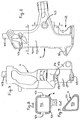
Die Fig. 6 bis 9 zeigen den zugehörigen Achsschenkelträger im Detail, nämlich
- Fig. 6
- in Vorderansicht,
- Fig. 7
- in Seitenansicht vom Rad her,
- Fig. 8
- im Schnitt entlang Schnittlinie D-D aus Fig. 6, und
- Fig. 9
- im Schnitt entlang Schnittlinie F-F aus Fig. 6.
- Fig. 6
- in front view,
- Fig. 7
- in side view from the bike,
- Fig. 8
- in section along section line DD of Fig. 6, and
- Fig. 9
- in section along section line FF from FIG. 6.
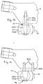
Fig. 10 und 11 zeigen alternative Anlenkungslösungen für den Dreieckslenker am Achsschenkelträger.10 and 11 show alternative linkage solutions for the wishbone at Steering knuckle.
In den Figuren sind der Übersichtlichkeit wegen gleiche bzw. einander entsprechende Teile mit gleichen Bezugszeichen angezogen. For the sake of clarity, the figures are the same or correspond to one another Parts drawn with the same reference numerals.
In der Zeichnung ist als Teil der dargestellten Vorderachse mit 1 ein lenkbares, luftgefedertes
Rad und mit 2 der dieses lagernde Radträger bezeichnet. Letzterer ist
um einen Achsschenkelbolzen 3 schwenkbar an einem Achsschenkelträger 4 angelenkt.
Dieser wiederum ist über mehrere Lenker an dem in der Zeichnung nur schematisch
angedeuteten Fahrzeugrahmen 5 angelenkt. Vom Lenkmechanismus für die
beiden Räder 1 der Achse sind in der Zeichnung ersichtlich ein Lenkgetriebe 6, das
über einen Hebelarm 7, eine daran angeschlossene Lenkstange 8, einen an dieser
angelenkten Kniehebel 9 und eine Spurstange 10 auf einen radträgerfest angeordneten
Lenkhebel 11 wirkt. Eine mittlere Spurstange 12 verbindet den Kniehebel 9 mit
der achsseitig gegenüberliegenden Radseite.In the drawing, as part of the front axle shown with 1 is a steerable, air-sprung
Wheel and designated with 2 of this bearing wheel carrier. The latter is
pivoted about a
Die Einzelradaufhängung für ein Rad 1 kennzeichnet sich erfindungsgemäß durch die Kombination
- a)
- eines als verwindungssteifes Guß- oder Schmiedeteil
ausgeführten Achsschenkelträgers 4 mit - b)
- einer Radführung mit einem
Dreieckslenker 13, zweiQuerlenkern Längslenker 16 in spezieller Anordnung, nämlich - b1)
- der
Dreieckslenker 13 ist - b1.1)
- in einer unteren Horizontalebene angeordnet und
- b1.2)
- schenkelinnenseitig am
Fahrzeugrahmen 5 sowie mit seinem Schenkelkniebereich am unteren Bereich desAchsschenkelträgers 4 angelenkt - b1.2.1)
- über jeweils
ein Gelenklager 17/1, 17/2, 17/3, - b2)
- die
beiden Querlenker - b2.1)
- stabförmig und gleich ausgebildet,
- b2.2)
- in einer oberen Horizontalebene parallel oder leicht gepfeilt zueinander und quer zur Fahrzeuglängsachse angeordnet,
- b2.3)
- außenendig am oberen Bereich des
Achsschenkelträgers 4, vorn bzw. hinten an diesem, und innenseitigam Fahrzeugrahmen 5 angelenkt - b2.3.1)
- über jeweils
ein verdrehweiches Lager 18, - b3)
der Längslenker 16 ist- b3.1)
- in einer Horizontalebene sich nach vorne oder hinten erstreckend angeordnet, sowie
- b3.2)
- einenendes am
Fahrzeugrahmen 5 und andernendes am oberen Bereich desAchsschenkelträgers 4 zu dessen Stabilisierung angelenkt - b3.2.1)
- über jeweils ein verdrehweiches Lager 19/1, 19/2.
- a)
- with a
stub axle 4 designed as a torsion-resistant cast or forged part - b)
- a wheel guide with a
wishbone 13, twowishbones arm 16 in a special arrangement, namely - b1)
- the wishbone is 13
- b1.1)
- arranged in a lower horizontal plane and
- b1.2)
- articulated on the inside of the thigh on the
vehicle frame 5 and with its thigh knee area on the lower area of thestub axle support 4 - b1.2.1)
- via a
joint bearing 17/1, 17/2, 17/3, - b2)
- the two
wishbones - b2.1)
- rod-shaped and of the same design,
- b2.2)
- arranged in an upper horizontal plane parallel or slightly swept to one another and transversely to the vehicle's longitudinal axis,
- b2.3)
- articulated on the outside of the upper area of the
steering knuckle 4, at the front or rear thereof, and on the inside on thevehicle frame 5 - b2.3.1)
- via a
rotatable bearing 18, - b3)
- the trailing
arm 16 is - b3.1)
- arranged in a horizontal plane extending forward or backward, and
- b3.2)
- one end articulated on the
vehicle frame 5 and the other end articulated on the upper region of thesteering knuckle 4 to stabilize it - b3.2.1)
- via a twist-soft bearing 19/1, 19/2.
Nachstehend ist auf Einzelheiten dieser Einzelradaufhängung näher eingegangen.The details of this independent suspension are discussed in more detail below.
Der Achsschenkelträger 4 ist zur Erzielung hoher Verwindungssteifigkeit als gegossener,
in sich profilierter Hohlkörper beispielsweise aus Stahlguß oder Sphäroguß
realisierbar. Einzelheiten und Details eines solchermaßen gegossenen Achsschenkelträger
4 sind aus den Figuren 6 bis 9 ersichtlich. Darin bezeichnen 4/1 die
Außenwand und 4/2 den eingeschlossenen Hohlraum des Achsschenkelträgers 4.
Mit 4/3 sind Guß-Kernaugen bezeichnet. Alternativ hierzu kann der Achsschenkelträger
4 aber auch als in sich querschnittsmäßig profiliertes Gesenkschmiedeteil,
z. B. aus Vergütungsstahl realisiert sein. Unabhängig von der spanlosen Herstellungsart
seiner Grundform wird die Endform des Achskörpers 4 durch entsprechende
spanabhebende Nachbearbeitung des Rohlings an erforderliche Stellen erzeugt.The
Bei dem in den Figuren 1 bis 9 gezeigten Ausführungsbeispiel übergreift der Dreieckslenker
13 mit seinen V-förmig gespreizten Schenkeln 13/1, 13/2 den dazwischen
durchragenden Achsschenkelträger 4 und ist mit seinem Schenkel-Kniebereich
an letzterem unten außen angelenkt.In the embodiment shown in Figures 1 to 9, the wishbone overlaps
13 with its V-shaped
Alternativ hierzu kann der Dreieckslenker 13 mit seinem Schenkel-Kniebereich - wie
die Beispiele gemäß Fig. 10 und 11 zeigen - fliegend an einem am unteren Ende
des Achsschenkelträgers 4 abragenden Lagerorgan 34 angelenkt sein. Hierauf ist
weiter hinten noch näher eingegangen. As an alternative to this, the
Der Dreieckslenker 13 ist schenkelinnenseitig wie auch im Kniebereich seiner
Schenkel 13/1, 13/2 über jeweils ein kugliges Molekular-Gelenklager 17/1, 17/2,
17/3 am Fahrzeugrahmen 5 bzw. Achsschenkelträger 4 angelenkt. Im einzelnen
weisen die beiden Schenkel 13/1, 13/2 des Dreieckslenkers 13 innenendig jeweils
ein Lagerauge 20/1 bzw. 20/2 auf. In jedes derselben ist als Bestandteil eines sich in
der Horizontalebene erstreckenden Molekular-Kugelpratzen-Gelenklagers 17/1 bzw.
17/2 ein wartungsfreies kugliges Molekularlager eingebaut. Über die äußeren Pratzen
der beiden Gelenklager 17/1, 17/2 ist der Dreieckslenker 13 am Fahrzeugrahmen
5, dort entsprechenden Lagerböcken (nicht dargestellt) angelenkt. Im Kniebereich
seiner beiden Schenkel 13/1, 13/2 weist der Dreieckslenker 13 ebenfalls ein
Lagerauge 21 mit eingebautem wartungsfreien kugligem Molekularlager auf. Dieses
ist im Fall des Ausführungsbeispieles gemäß Fig. 1 bis 9 Bestandteil eines sich vertikal
erstreckenden Molekular-Kugelpratzen-Gelenklagers 17/3, über dessen äußere,
vertikal angeordnete Pratzen der Dreieckslenker 13' außen am Achsschenkelträger
4 angelenkt ist. Hierzu weist letzterer in seinem unteren Bereich außen eine
maulförmige Einbuchtung 22 auf, in die der Dreieckslenker 13 mit seinem Lagerauge
21 partiell eintaucht. Oberhalb und unterhalb der Einbuchtung 22 sind am
Achsschenkelträger 4 Anlageflächen 23 für die Abstützung der Pratzen des Gelenklagers
17/3 und Gewindebohrungen 23/1 für die Festlegung derselben daran mittels
Schrauben gegeben.The
Im Fall der Beispiele gemäß Fig. 10 und 11 ist der Dreieckslenker 13 mit dem in seinem
Lagerauge 21 eingebauten, wartungsfreien kugligen Molekularlager 17/3 über
eine darin ausgebildete Konusbohrung auf einem kegligen Lagerzapfen 34/1 sitzend
an diesem befestigt. Dieser ein Bestandteil des Lagerorgans 34 bildende keglige
Lagerzapfen 34/1 ist am unteren Ende des Achsschenkelträgers 4 vertikal nach unten
abragend befestigt. Im Fall der Ausführungsform gemäß Fig. 10 ist der Lagerzapfen
34/1 Bestandteil eines Doppelkegelbolzens, der mit seinem oberen kegligen
Bolzenabschnnitt 34/2 in eine untenendig am Achsschenkelträger 4 ausgebildete
Konusbohrung eintaucht und in dieser form- und kraftschlüssig mit einer Schraube
34/3 arretiert ist, die hier gleichzeitig auch zur Festlagerung des Lagers 17/3 am
kegligen Lagerzapfen 34/1 dient. Im Fall der Ausführungsform gemäß Fig. 11 ist der
keglige Lagerzapfen 34/1 Bestandteil einer Halteplatte 34/4, die mittels Schrauben
34/5 am unteren Ende des Achsschenkelträgers 4 befestigt ist. Das Lager 17/3
ist in diesem Fall mittels einer Schraube 34/6 am kegligen Lagerzapfen 34/1 festgespannt.In the case of the examples according to FIGS. 10 and 11, the
Jeder der beiden identischen Querlenker 14, 15 hat ein innenendiges Lagerauge 24
und ein außenendiges Lagerauge 25 mit jeweils einer quer zur Lenker-Längsrichtung
verlaufenden Durchgangsbohrung, in die jeweils ein verdrehweiches, zylindrisches
Molekular-Buchsenlager 18 mit seiner zylindrischen Schlitzbuchse eingebaut
ist. An den einander zugewandten Stirnflächen der lenker-innenendigen
Schlitzbuchsen, ebenso an den einander zugewandten Stirnflächen der lenker-außenendigen
Schlitzbuchsen sind jeweils Kegelhülsen 26 abgestützt. Diese greifen
in entsprechende konische Bohrungsabschnitte ein, die paarweise einander gegenüberliegend
an den Enden zum einen einer Durchgangsbohrung in einem rahmenfesten
Lagerbock (nicht dargestellt) und zum anderen einer Durchgangsbohrung 27
im oberen Bereich des Achsschenkelträgers 4 ausgebildet sind. Mit 28 ist ein Zuganker
bezeichnet, der die beiden innenendigen Molekularlager-Schlitzbuchsen, die
beiden daran abgestützten Kegelhülsen 26 und die die zugehörigen konischen Bohrungsabschnitte
aufweisende Durchgangsbohrung am (nicht dargestellten) rahmenseitigen
Lagerbock durchdringt und zur innenendigen Befestigung der beiden Querlenker
14, 15 am Fahrzeugrahmen 5 dient. Mit 29 ist ein zum Zuganker 28 parallel
angeordneter Zuganker bezeichnet, der die beiden außenendigen Molekularlager-Schlitzbuchsen,
die beiden daran abgestützten Kegelhülsen 26 und die die zugehörigen
konischen Bohrungsabschnitte aufweisende Durchgangsbohrung 27 im Achsschenkelträger
4 durchdringt und zur außenendigen Befestigung der beiden Querlenker
14, 15 am Achsschenkelträger 4 dient. Dabei werden die beiden Lenker 14,
15 jeweils von außen her durch entsprechende axiale Vorspannung jedes der beiden
Zuganker 28, 29 am Lagerbock bzw. Achsschenkelträger 4 festgespannt, wobei
die Axialkraft über die beiden jeweils auf einem der Zuganker 28, 29 sitzenden Molekularlager-Schlitzbuchsen
auf die solchermaßen mit hoher Friktionskraft in die konischen
Bohrungsabschnitte gepreßten Kegelhülsen 26 übertragen wird.Each of the two
Der zur Lagestabilisierung des Achsschenkelträgers 4 in Fahrzeuglängsrichtung
dienende Längslenker 16 ist in einer Horizontalebene angeordnet, die sich parallel
zu jener den Dreieckslenker 13 aufnehmenden erstreckt, jedoch nahe zu den oberen
Querlenkern 14,15 hingerückt knapp unter (wie dargestellt) oder über diesen angeordnet
ist. Der Längslenker 16 kann sich dabei in der Horizontalebene schräg oder
parallel zur Fahrzeuglängsachse verlaufend vor oder hinter dem Achskörper 4, entweder
auf Zug oder Druck beansprucht, erstrecken. Unabhängig davon weist der
Längslenker 16 an jedem seiner beiden Enden ein Lagerauge 30 bzw. 31 mit jeweils
einer quer zur Lenker-Längsrichtung verlaufenden Durchgangsbohrung auf, in die
jeweils ein Molekular-Buchsenlager 19/1 bzw. 19/2 mit seiner zylindrischen Schlitzbuchse
eingebaut ist. Über die Pratzen des einen Molekular-Buchsenlagers 19/1 ist
die Verbindung des Längslenkers 16 zum oberen Bereich des Achsschenkelträgers
4 hergestellt, wobei an diesem entsprechende Anlageflächen 4/3 (siehe Fig. 6)
für die Abstützung der Pratzen und Gewindebohrungen zur Festlegung der letzteren
daran über Schrauben gegeben sind. Über die Pratzen mit zugehörigen Schrauben
des anderen Molekular-Buchsenlagers 19/2 ist die Verbindung des Längslenkers 16
zu einem nicht dargestellten fahrzeugrahmenfesten Lagerbock hergestellt.The for stabilizing the position of the
Vorzugsweise sind die Lenker 14, 15, 16 jeweils durch ein einteiliges Gesenkschmiedeteil
realisiert, können aber auch als Gußteil dargestellt werden, wobei das
Rohteil nach dem Ausformen an den notwendigen Stellen entsprechend spanabhebend
nachbearbeitet ist.The
Die vorbeschriebene Einzelradaufhängung ist ergänzt durch eine Feder-Dämpfer-Einrichtung
je Rad 1. Dabei ist ein Luftfederbalg 32 mit seinem untenendigen
Balgführungskopf 33 am oberen Ende 4/5 des entsprechend hochgezogenen Achsschenkelträgers
4 und mit seiner obenendigen Dichtplatte am Fahrzeugrahmen 5,
dort einem (nicht dargestellten) Lagerbock, angeschlossen. Ein vertikal leicht schräg
stehender Stoßdämpfer 35, der im Fall des Beispieles gemäß Fig. 1 bis 9 den Dreieckslenker
13 durchragt, ist obenendig am Fahrzeugrahmen, dort einem (nicht dargestellten)
Lagerbock, sowie untenendig am unteren Bereich des Achsschenkelträgers
4 innenseitig an diesem angelenkt. Hierzu sind an letzterem etwa in Höhe der
Einbuchtung 22 Mittel 36, beispielsweise ein Vorsprung oder Lageraugen, gegeben.The above-described independent suspension is supplemented by a spring-damper device
per wheel 1. There is an air bellows 32 with its lower end
Bellows guide
Je nach Fahrzeugtyp und -art, zum Beispiel bei einem Omnibus der Hochdecker-
und insbesondere der Doppeldecker-Bauart, kann es zweckmäßig sein bzw. sich als
erforderlich erweisen, einen Stabilisator 37 vorzusehen, der die Seitenneigung des
Fahrzeuges in Kurven und dessen Seitenwindempfindlichkeit reduziert sowie das
Wankverhalten verbessert. Ein solcher Stabilisator 37 kann in Draufsicht gesehen
U-förmig ausgebildet sein, die beiden je Achse gegebenen Achsschenkelträger 4
gelenkig miteinander verbinden und über (nicht dargestellte) Schwingen bzw. Lagerböcke
am Fahrzeugrahmen 5 aufgehängt sein. Die Anschlußstelle am Achsschenkelträger
ist duch das dortige Organ 4/6 gegeben.Depending on the vehicle type and type, for example the high-decker bus
and especially the double-decker design, it can be useful or as
prove necessary to provide a
Nachstehend noch einige Betrachtungen zu vorteilhaften Eigenschaften einer Achse mit den erfindungsgemäßen Radaufhängungen.Below are some considerations of advantageous properties of an axis with the wheel suspensions according to the invention.
Aufgrund der Anordnung der in parallelen Ebenen bei Fahrniveaulage liegt das Momentanzentrum
der Achse in Fahrbahnebene, es fehlt mithin der bei manchen
Radaufhängungen für die störende Seitenbeschleunigung verantwortliche Querkrafthebelarm.
Aufbau-Seitenbeschleunigungen sind daher bei einem Fahrzeug mit
der erfindungsgemäßen Einzelradaufhängung wirksam vermeidbar. Die gesamte
Achsführung, insbesondere aber die Lagerstellen selbst, halten Fahrbahngeräusche
vom Fahrzeugaufbau fern, sind wartungs- und praktisch verschleißfrei, kaum nachgiebig,
dennoch leicht drehbar und präzise. Während der unten liegende Dreieckslenker
13, wegen seiner großen Projektionslänge und der relativ kleinen Verdrehwinkel,
mit drei den auftretenden Belastungen angepaßten Molekular-Kugelpratzen-Gelenklagern
ausgerüstet ist, werden für das aufgelöste obere Lenkersystem 14, 15,
16 zylindrische Molekular-Schlitzbuchsenlager verwendet. Weil Einzellenker grundsätzlich
nur Kräfte in Lenker-Längsrichtung übertragen, sind diese Lenker 14, 15, 16
mit einfachen Querdurchgangsbohrungen für die jeweilige Lageraufnahme auch besonders
kostengünstig herzustellen. Schließlich zeichnen sich zylindrische Molekular-Schlitzbuchsenlager
durch hohe radiale Belastbarkeit, Radialsteifigkeit und Präzision
sowie große zulässige Verdrehwinkel und damit hohe Verdrehweichheit aus.
Alle diese Eigenschaften sind letztendlich auch entscheidend für ein gutes Ansprechverhalten
des gesamten Federungssystems, was sich voll auf den Fahrkomfort
auswirkt. Bei der Entwicklung der Einzelradaufhängung für die Achse wurde
auch besonders auf die Achseinbindungs-Peripherie am Fahrzeugrahmen geachtet,
dessen Struktursteifheit ein entscheidendes Kriterium für den Fahrkomfort darstellt.Due to the arrangement of the parallel levels at driving level, the momentary center is located
the axis in the carriageway level, so some are missing
Shear arm responsible for the side acceleration.
Body acceleration is therefore included in a vehicle
the independent suspension according to the invention can be effectively avoided. The whole
Axle guidance, but especially the bearings themselves, keep road noise
away from the vehicle body, are maintenance and practically wear-free, hardly flexible,
nevertheless easily rotatable and precise. While the wishbone below
13, because of its large projection length and the relatively small twist angle,
with three molecular ball claw spherical bearings adapted to the loads that occur
is equipped, for the dissolved
Claims (17)
- Independent wheel suspension for an air-sprung, steerable wheel (1) fitted to a bus/coach or truck and borne by a wheel carrier (2) which can be slewed about a kingpin (3) and is located on a steering-knuckle carrier (4) which in turn is located on the vehicle frame via several control arms, characterised by the combination of
- a)
- a steering-knuckle carrier (4) designed as a torsion-resistant cast or forged part with
- b)
- a wheel control system with an A-arm (13), two transverse control arms (14, 15) and a longitudinal arm (16) in special arrangement, namely that
- b1)
- the A-arm (13) is
- b1.1)
- arranged in a lower horizontal plane and
- b1.2)
- is located with the inside of its legs on the vehicle frame (5) and with its leg/knee area on the lower area of the steering-knuckle carrier (4)
- b1.2.1)
- in each case via a pivoting bearing (17/1, 17/2, 17/3),
- b2)
- the two transverse control arms (14, 15) are
- b2.1)
- bar-shaped, of identical design and,
- b2.2)
- in an upper horizontal plane, arranged parallel or slightly inclined towards each other and at right angles to the vehicle longitudinal axis and are,
- b2.3)
- located with their outer ends on the upper area of the steering-knuckle carrier (4) at its front and rear ends and with their inner ends on the vehicle frame (5),
- b2.3.1)
- in each case via a soft-turning bearing (18),
- b3)
- the longitudinal arm (16)
- b3,1)
- extends towards the front or rear in a horizontal plane and
- b3.2)
- is located with its one end on the vehicle frame (5) and with its other end on the upper area of the steering-knuckle carrier (4) for the stabilisation of said carrier (4),
- b3.2.1)
- in each case via a soft-turning bearing (19/1, 19/2).
- Independent wheel suspension according to Claim 1, characterised in that the A-arm (13) with its legs (13/1, 13/2) opened in V-shape arrangement extends beyond the steering-knuckle carrier (4) projecting in between said opened legs (13/1, 13/2) and is located with its leg/knee area on the outer lower end of said carrier (4).
- Independent wheel suspension according to Claim 1, characterised in that the A-arm (13) with its leg/knee area is floatingly located on a bearing organ (34; 34/1) projecting downwards at the lower end of the steering-knuckle carrier (4).
- Independent wheel suspension according to one of the Claims 1 to 3, characterised in that on the inner side of its legs and in the knee area of its two legs (13/1, 13/2) the A-arm (13) is located on the vehicle frame (5) and steering-knuckle carrier (4) via a spherical molecular pivoting bearing (17/1, 17/2, 17/3).
- Independent wheel suspension according to one of the foregoing Claims, characterised in that each of the two legs (13/1, 13/2) of the A-arm (13) has a bearing eye (20/1, 20/2) at its inner end, in each of which bearing eyes (20/1, 20/2) a maintenance-free spherical molecular bearing is installed as an integral part of a molecular ball-type claw pivoting bearing (17/1, 17/2) extending in the horizontal plane, and that the A-arm (13) is located with its inner end on a suitable bearing block on the vehicle frame (5) with the aid of associated bolts and via the outer claws of the two pivoting bearings (17/1, 17/2).
- Independent wheel suspension according to one of the Claims 1 and 2, characterised in that in the knee area of its two legs (13/1, 13/2) the A-arm (13) is provided with a bearing eye (21) in which a maintenance-free spherical molecular bearing is installed which in turn is an integral part of a vertically arranged molecular ball-type claw pivoting bearing (17/3) via whose outer vertical claws the A-arm (13) is located on the steering-knuckle carrier (4).
- Independent wheel suspension according to Claim 6, characterised in that in its lower outer area the steering-knuckle carrier (4) has a jaw-type recess (22) into which the A-arm (13) with its bearing eye (21) provided in the leg/knee area penetrates partially and that above and below said recess (22) on the steering-knuckle carrier (4) contact faces (23) with threaded bores (23/1) for the support and attachment of the claws of the pivoting bearing (17/3) are provided.
- Independent wheel suspension according to Claim 3, characterised in that a tapered bearing journal (34/1) perpendicularly projecting downwards is fitted to the lower end of the steering-knuckle carrier (4), on which tapered bearing journal (34/1) a spherical molecular bearing (17/3) with a corresponding conical bore is seated and fastened by means of a bolt (34/3) and installed in the bearing eye (21) provided in the leg/knee area of the A-arm (13).
- Independent wheel suspension according to Claim 1, characterised in that each of the two transverse control arms (14, 15) has a bearing eye (24) at the inner end and a bearing eye (25) at the outer end, each with a passage bore extending at right angles to the longitudinal direction of the arms, a cylindrical molecular bush bearing (18) with a cylindrical slot-type bush being installed in each passage bore, that in addition tapered sleeves (26) are supported on the mutually facing frontal faces of the two slot-type bushes at the inner ends of the arms and of the two slot-type bushes at the outer ends of the arms, which tapered sleeves (26) penetrate into corresponding the tapered bore sections which face one another in pairs and are located at the ends, on the one hand, of a passage bore in a bearing block firmly fitted to the frame and, on the other, of a passage bore (27) in the upper area of the steering-knuckle carrier (4) and that at their inner and outer ends the two transverse control arms (14, 15) are each located on the bearing block and the steering-knuckle carrier (4) via a tension bolt (28, 29), each of which transverse control arms penetrates the two slot-type bushes on the inner and outer sides, the two tapered sleeves (26) on the inner and outer sides of the arms and the passage bore in the bearing block and in the steering-knuckle carrier (4), which passage bore shows the conical bore sections, the axial force of the respective slot-type bush pair being transferred to the associated pair of tapered sleeves by means of the corresponding axial preload of each of the two tension bolts and, consequently, said associated pair of tapered sleeves being firmly clamped in the conical bore sections by means of high frictional force.
- Independent wheel suspension according to Claim 1, characterised in that the longitudinal arm (16) is arranged in a horizontal plane extending parallel to the one in which the A-arm (13) is arranged but being located close to the upper transverse control arms (14, 15), slightly below or above said transverse control arms (14, 15) and that the longitudinal arm (16) extends in the horizontal plane obliquely or parallel to the vehicle longitudinal axis.
- Independent wheel suspension according to one of the Claims 1 and 10, characterised in that at each of its two ends the longitudinal arm (16) is provided with a bearing eye (30, 31) in whose transverse passage bore a molecular bush bearing (19/1, 19/2) with a cylindrical slot-type bush is installed, the connection to the upper area of the steering-knuckle carrier (4) being established via the claws of the one molecular bush bearing (19/1) and the connection to a bearing block firmly fitted to the vehicle frame being established via the claws of the other molecular bush bearing (19/2).
- Independent wheel suspension according to Claim 1, characterised in that the two transverse control arms (14, 15) and the longitudinal arm (16) are each a one-piece drop-forged or cast part which has been shaped and then suitably machined at the required points in a metal-removing process.
- Independent wheel suspension according to Claim 1, characterised in that the steering-knuckle carrier (4) is designed as a cast, intrinsically shaped hollow body, made eg of cast steel or nodular graphite cast iron, which has been shaped and then suitably machined at the required points in a metal-removing process.
- Independent wheel suspension according to Claim 1, characterised in that the steering-knuckle carrier (4) is designed as a forged part with shaped cross-section, made eg of tempered steel, which has been shaped and then suitably machined at the required points in a metal-removing process.
- Independent wheel suspension according to Claim 1, characterised by its combination with one spring-damper device per wheel (1), in which device an air bellows (32) with its bellows guide cup (33) at its lower end is connected to the upper end of the steering-knuckle carrier (4) and at its upper end is connected with a sealing plate to a bearing block on the vehicle frame (5) and in which a shock absorber (35) extends through the transverse control arm (13) between its legs (13/1, 13/2) and is located with its upper end on the vehicle frame (5) and with its lower end on the inside of the lower area of the steering-knuckle carrier (4).
- Independent wheel suspension according to Claims 1 and 15, characterised by its combination with a stabiliser which when viewed from above is U-shaped, connects the two steering-knuckle carriers (4) per axle with each other in an articulated manner and is fastened to the vehicle frame (5) via rockers or bearing blocks.
- Independent wheel suspension according to Claim 15, characterised in that approximately at the height of the recess (22) the interior side of the steering-knuckle carrier (4) is provided with means (36), eg a projecting part or bearing eyes, for the lower support and location of the shock absorber (35).
Applications Claiming Priority (2)
| Application Number | Priority Date | Filing Date | Title |
|---|---|---|---|
| DE19619189A DE19619189A1 (en) | 1996-05-11 | 1996-05-11 | Independent wheel suspension for an air-sprung, steerable wheel of a bus or truck |
| DE19619189 | 1996-05-11 |
Publications (3)
| Publication Number | Publication Date |
|---|---|
| EP0806310A2 EP0806310A2 (en) | 1997-11-12 |
| EP0806310A3 EP0806310A3 (en) | 1999-05-12 |
| EP0806310B1 true EP0806310B1 (en) | 2001-11-28 |
Family
ID=7794143
Family Applications (1)
| Application Number | Title | Priority Date | Filing Date |
|---|---|---|---|
| EP97104006A Expired - Lifetime EP0806310B1 (en) | 1996-05-11 | 1997-03-11 | Independent suspension for a steered air suspended wheel of a bus or lorry |
Country Status (5)
| Country | Link |
|---|---|
| EP (1) | EP0806310B1 (en) |
| DE (2) | DE19619189A1 (en) |
| ES (1) | ES2163675T3 (en) |
| HU (1) | HU223132B1 (en) |
| TR (1) | TR199700336A3 (en) |
Cited By (1)
| Publication number | Priority date | Publication date | Assignee | Title |
|---|---|---|---|---|
| DE102010004321A1 (en) | 2010-01-12 | 2011-07-14 | MAN Truck & Bus AG, 80995 | Commercial vehicle with a connection of a wishbone |
Families Citing this family (15)
| Publication number | Priority date | Publication date | Assignee | Title |
|---|---|---|---|---|
| CN1100689C (en) * | 1997-12-12 | 2003-02-05 | 荷兰新维国际有限公司 | independent front suspension |
| SE518449C2 (en) | 1999-10-18 | 2002-10-08 | Volvo Lastvagnar Ab | Wheel suspension |
| DE10007192C2 (en) * | 2000-02-17 | 2002-10-24 | Benteler Werke Ag | Handlebars for motor vehicles |
| DE10061408A1 (en) | 2000-12-09 | 2002-06-13 | Zahnradfabrik Friedrichshafen | Steering device for steerable front wheels |
| DE10061407A1 (en) * | 2000-12-09 | 2002-06-13 | Zahnradfabrik Friedrichshafen | Independent wheel suspension for a sprung, steerable wheel |
| US6866295B2 (en) | 2000-12-28 | 2005-03-15 | Dana Corporation | Modular cast independent front suspension subframe |
| ITTO20020268A1 (en) * | 2002-03-26 | 2003-09-26 | Iveco Fiat | INDEPENDENT SUSPENSION FOR A WHEEL OF AN INDUSTRIAL VEHICLE. |
| US6783137B2 (en) | 2002-11-14 | 2004-08-31 | Tuthill Corporation | Steering knuckle carrier-to-suspension arm pivotal connection and method of assembling and preloading the pivotal connection |
| GB2405381A (en) * | 2003-09-01 | 2005-03-02 | Ford Global Tech Llc | Five-link vehicle suspension system |
| DE102005035913A1 (en) * | 2005-07-28 | 2007-02-08 | Zf Friedrichshafen Ag | Motor vehicle chassis |
| DE102006031708A1 (en) * | 2006-07-08 | 2008-01-10 | Daimlerchrysler Ag | Making axle pivot for motor vehicle involves producing functional surfaces of base body and brake carrier and of axle journal in separate components, inserting axle journal into base body opening, joining to counterpart by pressure welding |
| FR2914586A1 (en) * | 2007-04-03 | 2008-10-10 | Renault Sas | MULTI-ARM REAR TRAIN FOR MOTOR VEHICLE |
| CN103075452B (en) * | 2013-01-25 | 2015-12-02 | 安徽江淮汽车股份有限公司 | A kind of air suspension guiding spring assembly |
| CN105059074B (en) * | 2015-09-08 | 2018-02-02 | 北京航天发射技术研究所 | suspension limiter, suspension system and vehicle with overload protection function |
| CN113635722A (en) * | 2021-08-16 | 2021-11-12 | 西南交通大学 | A semi-active suspension system suitable for in-wheel motor-driven virtual rail trains |
Family Cites Families (12)
| Publication number | Priority date | Publication date | Assignee | Title |
|---|---|---|---|---|
| US2934352A (en) * | 1956-11-19 | 1960-04-26 | Gen Motors Corp | Vehicle fluid suspension |
| FR1232152A (en) * | 1958-08-12 | 1960-10-06 | Guy Motors Ltd | Suspension for vehicles with independent steered wheels |
| AT295337B (en) * | 1968-08-20 | 1971-12-27 | Bayerische Motoren Werke Ag | Independent suspension of the steered wheels of motor vehicles, especially passenger cars |
| BE789857A (en) * | 1971-10-13 | 1973-02-01 | Carrozzeria | FRONT PNEUMATIC SUSPENSION WITH INDEPENDENT WHEELS FOR BUSES AND INDUSTRIAL VEHICLES |
| DE2624704B1 (en) * | 1976-06-02 | 1978-04-27 | Georg Fischer Ag, Schaffhausen (Schweiz) | One-piece swivel bearing designed as a cast part for a steered vehicle wheel |
| DE2918605A1 (en) * | 1979-05-09 | 1980-11-13 | Daimler Benz Ag | SINGLE WHEEL SUSPENSION BY MEANS OF LEADERS |
| DE3345952A1 (en) * | 1983-12-20 | 1985-06-27 | Fa. Gotthard Drögmöller, 7100 Heilbronn | Rotary bearing connection between spring carrier and transverse link in the front axle suspension of a motor vehicle |
| JPS6121802A (en) * | 1984-07-10 | 1986-01-30 | Nissan Motor Co Ltd | Suspension of vehicle |
| DE3718137A1 (en) * | 1987-05-29 | 1988-12-15 | Man Nutzfahrzeuge Gmbh | Independent suspension for a steerable wheel on a commercial vehicle |
| DE4017210C1 (en) * | 1990-05-29 | 1991-10-31 | Mercedes-Benz Aktiengesellschaft, 7000 Stuttgart, De | |
| FR2675431B1 (en) * | 1991-04-16 | 1993-07-16 | Renault | VEHICLE SUSPENSION DEVICE WITH ARTICULATED LEG. |
| FR2707926B1 (en) * | 1993-06-29 | 1995-10-06 | Peugeot | Improved suspension device for a front wheel of a motor vehicle. |
-
1996
- 1996-05-11 DE DE19619189A patent/DE19619189A1/en not_active Withdrawn
-
1997
- 1997-03-11 EP EP97104006A patent/EP0806310B1/en not_active Expired - Lifetime
- 1997-03-11 DE DE59705492T patent/DE59705492D1/en not_active Expired - Lifetime
- 1997-03-11 ES ES97104006T patent/ES2163675T3/en not_active Expired - Lifetime
- 1997-03-21 HU HU9700626A patent/HU223132B1/en active IP Right Grant
- 1997-05-01 TR TR97/00336A patent/TR199700336A3/en unknown
Cited By (2)
| Publication number | Priority date | Publication date | Assignee | Title |
|---|---|---|---|---|
| DE102010004321A1 (en) | 2010-01-12 | 2011-07-14 | MAN Truck & Bus AG, 80995 | Commercial vehicle with a connection of a wishbone |
| EP2351656A1 (en) | 2010-01-12 | 2011-08-03 | MAN Truck & Bus AG | Commercial vehicle with a triangular control arm |
Also Published As
| Publication number | Publication date |
|---|---|
| ES2163675T3 (en) | 2002-02-01 |
| EP0806310A2 (en) | 1997-11-12 |
| TR199700336A2 (en) | 1998-10-21 |
| HUP9700626A3 (en) | 2000-02-28 |
| EP0806310A3 (en) | 1999-05-12 |
| DE59705492D1 (en) | 2002-01-10 |
| HU9700626D0 (en) | 1997-05-28 |
| TR199700336A3 (en) | 1998-10-21 |
| HUP9700626A2 (en) | 1998-11-30 |
| HU223132B1 (en) | 2004-03-29 |
| DE19619189A1 (en) | 1997-11-13 |
Similar Documents
| Publication | Publication Date | Title |
|---|---|---|
| DE102004058698B3 (en) | Adjustable spring wheel suspension for motor vehicle has coil spring arranged with force direction line deviating from geometrical center line of spring | |
| DE60125410T2 (en) | VEHICLE SUSPENSION SYSTEM | |
| EP0656270B1 (en) | Wheel suspension | |
| DE10053411B4 (en) | vehicle axle | |
| EP0141092B1 (en) | Independent motor vehicle wheel suspension | |
| EP0806310B1 (en) | Independent suspension for a steered air suspended wheel of a bus or lorry | |
| DE19743736B4 (en) | front suspension | |
| DE3740310C2 (en) | ||
| EP2514616B1 (en) | Wheel suspension for an axle of a motor vehicle | |
| DE10133424A1 (en) | Rear axle for vehicle has upper two of five individual rods set in front of spring and/or damper element mounted between vehicle superstructure and one of lower guide rods | |
| DE102016220786B4 (en) | Rear suspension for motor vehicles | |
| DE102013210338A1 (en) | Multi-link rear axle for a vehicle | |
| DE10032961B4 (en) | Torsion bar | |
| EP1080953A1 (en) | Motor vehicle wheel suspension with a wheel guiding leaf spring | |
| EP1900554A1 (en) | Individual wheel suspension of a double wishbone type | |
| EP3452310B1 (en) | Single-wheel suspension arrangement of a vehicle having a wheel-controlling leaf spring element composed of a fiber composite material | |
| WO2020038855A1 (en) | Rear axle of a vehicle | |
| EP0873891A2 (en) | Independent suspension for steered wheels of motor vehicles, especially passenger vehicles | |
| DE60306730T2 (en) | Steering device for the carrying device of the rear hub in motor vehicles | |
| WO2004069567A1 (en) | Wheel suspension for motor vehicles | |
| DE10061407A1 (en) | Independent wheel suspension for a sprung, steerable wheel | |
| DE1959844A1 (en) | Rear axle suspension | |
| EP1110848B1 (en) | Trailing arm frame in commercial vehicles | |
| DE102017211277B4 (en) | Wheel suspension for a motor vehicle | |
| DE4008465A1 (en) | PRELVETABLE BEARING |
Legal Events
| Date | Code | Title | Description |
|---|---|---|---|
| PUAI | Public reference made under article 153(3) epc to a published international application that has entered the european phase |
Free format text: ORIGINAL CODE: 0009012 |
|
| AK | Designated contracting states |
Kind code of ref document: A2 Designated state(s): BE DE ES FR IT NL |
|
| PUAL | Search report despatched |
Free format text: ORIGINAL CODE: 0009013 |
|
| AK | Designated contracting states |
Kind code of ref document: A3 Designated state(s): BE DE ES FR IT NL |
|
| 17P | Request for examination filed |
Effective date: 19990616 |
|
| GRAG | Despatch of communication of intention to grant |
Free format text: ORIGINAL CODE: EPIDOS AGRA |
|
| 17Q | First examination report despatched |
Effective date: 20010302 |
|
| GRAG | Despatch of communication of intention to grant |
Free format text: ORIGINAL CODE: EPIDOS AGRA |
|
| GRAH | Despatch of communication of intention to grant a patent |
Free format text: ORIGINAL CODE: EPIDOS IGRA |
|
| GRAH | Despatch of communication of intention to grant a patent |
Free format text: ORIGINAL CODE: EPIDOS IGRA |
|
| ITF | It: translation for a ep patent filed | ||
| GRAA | (expected) grant |
Free format text: ORIGINAL CODE: 0009210 |
|
| AK | Designated contracting states |
Kind code of ref document: B1 Designated state(s): BE DE ES FR IT NL |
|
| REF | Corresponds to: |
Ref document number: 59705492 Country of ref document: DE Date of ref document: 20020110 |
|
| REG | Reference to a national code |
Ref country code: ES Ref legal event code: FG2A Ref document number: 2163675 Country of ref document: ES Kind code of ref document: T3 |
|
| ET | Fr: translation filed | ||
| PLBE | No opposition filed within time limit |
Free format text: ORIGINAL CODE: 0009261 |
|
| STAA | Information on the status of an ep patent application or granted ep patent |
Free format text: STATUS: NO OPPOSITION FILED WITHIN TIME LIMIT |
|
| 26N | No opposition filed | ||
| REG | Reference to a national code |
Ref country code: NL Ref legal event code: TD Effective date: 20110420 |
|
| REG | Reference to a national code |
Ref country code: FR Ref legal event code: CD |
|
| REG | Reference to a national code |
Ref country code: ES Ref legal event code: PC2A Owner name: "MAN TRUCK & Effective date: 20110620 Ref country code: ES Ref legal event code: PC2A Owner name: MAN TRUCK & BUS AG Effective date: 20110620 |
|
| REG | Reference to a national code |
Ref country code: DE Ref legal event code: R081 Ref document number: 59705492 Country of ref document: DE Owner name: MAN TRUCK & BUS AG, DE Free format text: FORMER OWNER: MAN NUTZFAHRZEUGE AG, 80995 MUENCHEN, DE Effective date: 20110518 |
|
| REG | Reference to a national code |
Ref country code: FR Ref legal event code: PLFP Year of fee payment: 20 |
|
| PGFP | Annual fee paid to national office [announced via postgrant information from national office to epo] |
Ref country code: NL Payment date: 20160324 Year of fee payment: 20 |
|
| PGFP | Annual fee paid to national office [announced via postgrant information from national office to epo] |
Ref country code: FR Payment date: 20160331 Year of fee payment: 20 Ref country code: BE Payment date: 20160324 Year of fee payment: 20 |
|
| PGFP | Annual fee paid to national office [announced via postgrant information from national office to epo] |
Ref country code: DE Payment date: 20160531 Year of fee payment: 20 Ref country code: ES Payment date: 20160422 Year of fee payment: 20 |
|
| PG25 | Lapsed in a contracting state [announced via postgrant information from national office to epo] |
Ref country code: IT Free format text: LAPSE BECAUSE OF NON-PAYMENT OF DUE FEES Effective date: 20160311 |
|
| REG | Reference to a national code |
Ref country code: DE Ref legal event code: R071 Ref document number: 59705492 Country of ref document: DE |
|
| REG | Reference to a national code |
Ref country code: NL Ref legal event code: MK Effective date: 20170310 |
|
| PG25 | Lapsed in a contracting state [announced via postgrant information from national office to epo] |
Ref country code: IT Free format text: LAPSE BECAUSE OF NON-PAYMENT OF DUE FEES Effective date: 20160311 |
|
| PGFP | Annual fee paid to national office [announced via postgrant information from national office to epo] |
Ref country code: IT Payment date: 20160325 Year of fee payment: 20 |
|
| PGRI | Patent reinstated in contracting state [announced from national office to epo] |
Ref country code: IT Effective date: 20170710 |
|
| REG | Reference to a national code |
Ref country code: ES Ref legal event code: FD2A Effective date: 20180508 |
|
| PG25 | Lapsed in a contracting state [announced via postgrant information from national office to epo] |
Ref country code: ES Free format text: LAPSE BECAUSE OF EXPIRATION OF PROTECTION Effective date: 20170312 |