EP0806170A2 - Reinigungsgerät mit einer dreieckförmigen Befestigungsvorrichtung zur Kopplung und schnellen Entkopplung - Google Patents
Reinigungsgerät mit einer dreieckförmigen Befestigungsvorrichtung zur Kopplung und schnellen Entkopplung Download PDFInfo
- Publication number
- EP0806170A2 EP0806170A2 EP97302901A EP97302901A EP0806170A2 EP 0806170 A2 EP0806170 A2 EP 0806170A2 EP 97302901 A EP97302901 A EP 97302901A EP 97302901 A EP97302901 A EP 97302901A EP 0806170 A2 EP0806170 A2 EP 0806170A2
- Authority
- EP
- European Patent Office
- Prior art keywords
- attachment
- cleaning
- stud
- motor
- receiving area
- Prior art date
- Legal status (The legal status is an assumption and is not a legal conclusion. Google has not performed a legal analysis and makes no representation as to the accuracy of the status listed.)
- Withdrawn
Links
Images


Classifications
-
- F—MECHANICAL ENGINEERING; LIGHTING; HEATING; WEAPONS; BLASTING
- F16—ENGINEERING ELEMENTS AND UNITS; GENERAL MEASURES FOR PRODUCING AND MAINTAINING EFFECTIVE FUNCTIONING OF MACHINES OR INSTALLATIONS; THERMAL INSULATION IN GENERAL
- F16D—COUPLINGS FOR TRANSMITTING ROTATION; CLUTCHES; BRAKES
- F16D1/00—Couplings for rigidly connecting two coaxial shafts or other movable machine elements
- F16D1/10—Quick-acting couplings in which the parts are connected by simply bringing them together axially
- F16D1/108—Quick-acting couplings in which the parts are connected by simply bringing them together axially having retaining means rotating with the coupling and acting by interengaging parts, i.e. positive coupling
- F16D1/112—Quick-acting couplings in which the parts are connected by simply bringing them together axially having retaining means rotating with the coupling and acting by interengaging parts, i.e. positive coupling the interengaging parts comprising torque-transmitting surfaces, e.g. bayonet joints
-
- A—HUMAN NECESSITIES
- A46—BRUSHWARE
- A46B—BRUSHES
- A46B13/00—Brushes with driven brush bodies or carriers
- A46B13/008—Disc-shaped brush bodies
-
- Y—GENERAL TAGGING OF NEW TECHNOLOGICAL DEVELOPMENTS; GENERAL TAGGING OF CROSS-SECTIONAL TECHNOLOGIES SPANNING OVER SEVERAL SECTIONS OF THE IPC; TECHNICAL SUBJECTS COVERED BY FORMER USPC CROSS-REFERENCE ART COLLECTIONS [XRACs] AND DIGESTS
- Y10—TECHNICAL SUBJECTS COVERED BY FORMER USPC
- Y10T—TECHNICAL SUBJECTS COVERED BY FORMER US CLASSIFICATION
- Y10T403/00—Joints and connections
- Y10T403/70—Interfitted members
- Y10T403/7005—Lugged member, rotary engagement
Definitions
- the present invention relates to a motorised cleaning device and, more particularly, to a device with a removable cleaning attachment.
- U.S. Patent 4,662,024 discloses a floor maintenance machine with a hub having three lugs and a coupling device with a mating aperture.
- U.S. Patents 2,561,279 and 3,600,735 show similar designs with biasing springs.
- Various types of removable connecting mounts can be found in the following U.S. Patents: U.S. Patent 3,251,086 U.S. Patent 1,373,206 U.S. Patent 3,423,781 U.S. Patent 2,527,256 U.S. Patent 2,337,402 U.S.
- the present invention provides a cleaning apparatus having a housing, a motor located in the housing, and a transmission connecting an output shaft of the motor to a mount for attaching a cleaning attachment, characterised in that the mount has a leading section with a general triangular block shape and a shaft section, the leading section having three generally triangular shaped cantilevered tips.
- the present invention further provides a cleaning apparatus having a housing, a motor and a cleaning attachment removably connected to the motor by a removable mounting system, characterised in that said removable mounting system has a first member including a mounting stud having a leading section with a generally triangular block shape and a shaft section located behind the leading section, and a second one of the members of the mounting system has a receiving area with the mounting stud being located therein, the receiving area having a generally triangular shaped aperture into the receiving area through which the leading section of the mounting stud is passed.
- the present invention further provides a hand held cleaning apparatus comprising:
- the present invention further provides a cleaning attachment for use with a motorised cleaning apparatus, the cleaning attachment having a frame and a cleaning section attached to the frame, the frame having a receiving area for locating an attachment mount of the apparatus therein, characterised in that the receiving area has a generally triangular shaped aperture through which the attachment mount must pass to enter the receiving area.
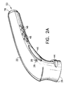
- FIG. 1 there is shown a perspective view of a battery operated cleaning apparatus 10 incorporating features of the present invention.
- a battery operated cleaning apparatus 10 incorporating features of the present invention.
- the present invention will be described with reference to the embodiments shown in the drawings, it should be understood that features of the present invention can be embodied in various alternative forms of embodiments.
- any suitable size, shape or type of elements or materials could be used.
- the apparatus 10 generally comprises a housing 12, a battery cap 14, a battery 16, a motor 18, and a cleaning attachment 20.
- the housing 12 generally comprises a subassembly housing or shell 22 and a cover 24.
- the subassembly shell 22 comprises two half members 26; one of which is shown in Figure 2.
- the two members 26 are basically mirror images of each other and held together by a single screw 29 at the holes 28 and metal rings 31 at the front and rear of the members 26. In an alternate embodiment, only one ring 31 is needed at the front of the shell 22. In another alternate embodiment, there might be no metal rings used.
- the interiors of the members 26 have a honeycomb configuration provided by structural strut sections 30.
- the members 26 also have four areas 32, 34, 36, 38 for receiving the battery 16, the motor 18, a switch 40, and an attachment mount 42, respectively.
- each member 26 has raised areas 44, 46, 48.
- the cover 24 is injection moulded over the subassembly shell 22 as further described below.
- the cover 24 is preferably comprised of SANTOPRENE.
- SANTOPRENE is a trademark of Advanced Elastomer Systems of Akrqn, Ohio.
- the cover 24 (see Figure 1) forms an outer skin over a majority of the subassembly shell 22.
- the cover 24 also forms a hand guard section 66.
- the hand guard section 66 extends along the bottom of the apparatus 10 between the rear end of the handle section 68 and the bottom of the front head section 70. This forms a loop. A user's fingers can extend into that loop.
- the motor 18 is preferably a brushless DC motor with an output shaft 52 and electrical terminals 54.
- the motor 18 is located in a motor/gear support cage 56 before being placed between the two members 26.
- gears 58 that form a transmission between the drive shaft 52 and the mount 42.
- the gears 58 form a planetary gear transmission to convert the high speed low torque output of the motor into a slower speed higher torque output for the tool.
- the advantages of this approach are robustness of a planetary gear system and over all smaller space requirements.
- the planetary gear approach is robust because it is forgiving in the sense that the unit doesn't require the tight manufacturing tolerances and the system has no side loads applied to the gears.
- the planetary gear approach is a physically smaller approach for this particular design approach in the regard that a tremendous reduction gear ratio is achievable without having a large space requirement with respect to distance for the motor centreline.
- other gearing approaches could be used, such as spur gears, bevel gears, helical gears or worm gears.
- the motor 18 and cage 56 are received in the receiving aperture 34 such that it forms a structural support between the two members 26. This structural support cooperates with the structure of the members 26 for the purpose of withstanding compression during overmoulding of the cover 24.
- the terminals 54 of the motor are connected by wires to the switch 40 and two spring contact terminals 60, 61.
- the terminals 60, 61 are located at the interior end of the battery receiving area 32.
- the battery receiving area 32 has a general tubular shape.
- the battery 16 has a general column shape with two coaxial terminals 62, 63.
- the first terminal 60 is located to make contact with the centre terminal 62 of the battery 16.
- the second terminal 61 is located to make contact with the outer terminal 63 of the battery 16.
- the two battery terminals are generally coaxially located relative to each other at a single end of the battery 16.
- the battery 16 is preferably a rechargeable battery such as a VERSAPAK battery sold by Black & Decker (U.S.) Inc.
- VERSAPAK is a trademark of The Black & Decker Corporation of Towson, Maryland.
- any suitable type of battery could be used.
- the apparatus could be modified to accept any suitable type of battery or batteries.
- the rear end 76 of the battery extends out of the aperture 50 past the rear end of the housing.
- the two spring contact terminals 60, 61 form a frictional engagement with the two coaxial terminals 62, 63 of the battery 16.
- the terminal 61 does not extend into the annular groove 65 along the outer battery terminal. Therefore, the terminal 61 does not make a snap-lock retainment with the annular groove 65.
- the frictional forces between the spring contact terminals 60, 61 and the coaxial terminals 62, 63 is sufficient to retain the battery 16 inside the battery receiving area 32, even when the battery cap 14 is not connected to the housing 12, until intentionally removed by a user.
- this frictional engagement could be insufficient to mechanically retain the weight of the battery when the battery is vertically located below the spring contact terminals 60, 61.
- the first terminal 60 is connected by a wire directly to one of the terminals 54 of the motor 18.
- the second terminal 61 is connected by a wire to the switch 40 which, in turn, is connected by a wire to one of the terminals 54 of the motor 18.
- the switch 40 is preferably a push-button ON/OFF switch. However, in alternate embodiments, any suitable type of switch could be used.
- the base of the switch 40 is stationarily positioned in the receiving area 36. Covering the switch 40 is a button cover 64.
- the button cover 64 is comprised of a flexible polymer material such that it can be deflected by a user's finger to actuate the switch 40.
- the battery cap 14 is preferably made of a polymer material.
- the battery cap 14 has a front edge 72 with a wavy shape having peaks and valleys.
- the battery cap 14 also has a receiving area 74 for receiving the rear end 76 (see Figure 2) of the battery 16.
- the rear end of the housing 12 has a ledge 78 (see Figure 2).
- the cover 24 does not extend onto the ledge 78.
- the ledge 78 has a general ring shape at the entrance of the battery receiving area.
- the rear edge 80 of the cover 24 has a wavy shape with peaks and valleys that is complimentary to the front edge 72 of the battery cap 14.
- the rear edge 80 is located next to the ledge 78 and outward relative to the ledge.
- the battery cap 14 is friction mounted on the ledge 78 of the subassembly shell 22.
- the ledge 78 has a smooth outer surface such that only frictional grasping of the battery cap 14 on the ledge retains the battery cap to the ledge.
- a user merely slides the cap onto the ledge by pushing the cap and housing 12 together. As seen in Fig. 3A, when the battery cap 14 is properly connected to the housing 12, the two edges 72, 80 mate with each other.
- the frictional connection of the battery cap 14 to the ledge 78 is relatively strong and forms a watertight seal.
- the user can use the edges 72, 80 to function as a cam.
- a user merely axially rotates the battery cap 14 on the ledge 78 as indicated by arrow A. This causes the slopes leading up to the peaks to coact against each other to move the battery cap 14 in direction B.
- axial rotation of the battery cap relative to the housing causes the battery cap to be cammed away from the housing by the cam surfaces.
- the battery cap 14 has a bottom section 75 that extends downward off centre from the centreline of the mounting of the battery cap on the ledge. This off centre section 75 has been provided to give a user better leverage in axially rotating the cap 14 on the ledge 78.
- the camming action between the cap 14 and the cover 24 need not completely push the cap 14 off the ledge 78, but preferably moves the cap 14 a majority of the length of the ledge 78. In alternate embodiments other types of battery cap removal assistance could be provided.
- the battery cap 14 is provided to close off the aperture 50 and form a watertight seal with the ledge 78.
- the battery cap 14 functions as a retainer to keep the battery 16 attached to the terminals 60, 61 and inside the battery receiving area.
- the terminal 61 does not interact with the groove 65 of the battery 16 to retain the battery. This has been purposely done to encourage users to only use the apparatus 10 with the battery cap 14 in place.
- the frictional engagement between the terminals of the battery and the apparatus is insufficient to mechanically retain the weight of the battery when the battery is vertically oriented beneath the terminals 60, 61; even partially.
- the user In order to prevent the battery 16 from automatically sliding out of the housing, the user merely needs to slide the battery cap 14 onto the ledge 78. If a user tries to use the apparatus without the battery cap 14, and tilts the rear end of the housing down, the battery 16 will slide out of the housing under its own weight.
- This design allows an easy attachment and removal of the battery cap using an intuitive rotating motion and requires no secondary sealing gasket for the battery cap.
- Alternative designs could include a bayonet design or a snap-lid with a thumbnail lip.
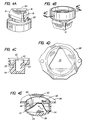
- the attachment mount 42 generally comprises a one-piece polymer member that is attached to an output shaft from the transmission 58.
- the mount 42 includes a stud with a shaft receiving area 82 and a leading section 84 that has a general triangular block shape.
- the mount 42 also has a relatively narrow neck or shaft section 83 behind the leading section 84. This forms slots 85 behind cantilevered generally triangular shaped tips 81 of the leading section 84.
- FIGs 4D and 4E portions of the cleaning attachment 20 are shown.
- the attachment 20 generally comprises a frame 86 and bristles 88 (see Figure 1).
- FIG 4D shows a partial top plan view of the centre of the frame 86.
- the frame 86 has a centre generally triangular shaped aperture 90.
- the aperture 90 is about the same size and shape as the leading section 84 of the mount 42 such that the leading section 84 can pass therethrough.
- Figure 4E is a partial perspective cutaway view of the frame 86 at the aperture 90. Located behind the aperture 90 is a receiving area 92.
- the receiving area 92 has three retaining shelves 94 and three stop blocks 96.
- the mount section 84 is merely inserted through the aperture 90 into the receiving area 92.
- the frame 86 and mount 42 are then rotated relative to each other such that the triangular tips 81 of the leading section 84 move behind the shelves 94.
- the shelves 94 are received in the slots 85 of the mount 42.
- the stop blocks 96 stop the relative rotation of the mount 42 by contacting the triangular tips 81. This interlocking of the mount 42 and frame 86 keeps the attachment 20 connected to the mount 42.
- the motor 18 and transmission 58 are only capable of rotating the mount 42 in one direction C shown in Figures 1 and 4E.
- a user In order to disconnect or remove the attachment 20, a user merely rotates the attachment 20 by hand in a direction reverse to direction C until the leading section 84 aligns with the aperture 90. Then, the attachment 20 can be separated from the mount 42.
- the areas of contact between the shelves 94 and the rear sides of the tips 81 is sufficiently large to provide sufficient frictional force to inhibit unintentional relative rotation between the mount 42 and the frame in a direction reverse to direction C without any additional biasing or holding between the two.
- a user because only friction is being used to prevent relative rotation in a direction reverse to direction C, a user only needs to use minimal force to rotate the cleaning attachment 20 in a disconnection direction. Therefore, the user does not need to grab a large area of the cleaning attachment, which might otherwise be very dirty from use.
- a short spiral mounting system could be provided.
- Other alternatives could include a one or two blade bayonet design.
- the three blade or trilobular bayonet design of the mount 42 is preferred because it is a simple attachment and removable by executing about a 1/6 turn.
- a counterclockwise engaging system could also be used rather than a clockwise engaging system.
- Another alternate embodiment could include the cleaning attachment having the mount and the apparatus having the receiving area.
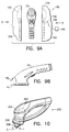
- the apparatus 10 is shown with a user grasping the apparatus 10 at two different locations. More specifically, the housing 12 has been designed to provide two primary hand holding positions.
- Primary hand holding position is intended to mean a position in which a users' hand can comfortably and surely hold the apparatus during use; i.e.: a location specifically and intentionally designed for the user to hold the apparatus during use.
- the two primary hand holding positions allow a user to properly hold the apparatus 10 based upon the type of attachment being used and/or the type of cleaning task.
- the shape of the housing also allows for easy articulation around items, such as bathroom fixtures.
- Figure 5A shows a user grasping the apparatus 10 at the handle section 68 and cleaning tiles on a wall 98.
- the handle section 68 has a general tubular shape, with the battery 16 therein, for this purpose.
- the handle section 68 extends rigidly from a top rear portion of the head section. This holding position allows the user to scrub areas at a distance, such as above the user's head.
- the button cover 64 and switch 40 are suitably located to be depressed by the user's index finger in this holding position.
- the hand guard section 66 protects the user's knuckles from hitting the wall 98.
- Figure 5B shows the user grasping the apparatus 10 at the top of the head section 70 and cleaning tiles on a floor 100.
- the top of the head section 70 has been provided with a curved palm contact area 102 and a ridge 104 with an inwardly and downwardly sloping surface 106 below it.
- the ridge 104 is located at a perimeter of the top surface of the head section 70.
- a bottom portion 108 of the head section 70 has a general bell shaped outer perimeter.
- the bottom portion 108 has a centre axis that is angled relative to a centre axis of the handle section 68 at an angle D (see Figure 1) of about 95° to about 120°. In a preferred embodiment, the angle D is about 100°. However, any suitable angle could be provided.
- the surface 106 extends around a majority of the top surface of the head section.
- the curve of the top surface area 102 of the head section 70 has been configured to be matingly or comfortably received in a user's palm with the user's fingers wrapping around the ridge 104 and along the sloping surface 106.
- This shape provides for a grasping position as shown in Fig. 5B where the user can locate his hand directly behind the cleaning attachment 20.
- This grasping position allows the user to exert additional force for the cleaning attachment 20 against the floor 100 with minimal additional effort, such as when using a relatively large diameter rotary scrub attachment or for heavy duty scrubbing.
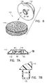
- the attachment 110 generally comprises a frame 112 and a cleaning section 114.
- the frame 112 is comprised of a one-piece moulded plastic or polymer member.
- the frame 112 has a mounting section 116 for the mount 42 of the apparatus 10 and a cleaning pad attachment surface 118 on its bottom.
- the mounting section 116 is substantially the same as that shown in Figures 4D and 4E.
- the mounting section 116 has a generally triangular shaped aperture 90' into a receiving area 92' with three shelves 94' and three blocks 96'.
- the frame 112 could be comprised of multiple members fixedly connected to one another. Other types of mounting sections could be provided such that the attachment could be used with other types of cleaning apparatus.
- the bottom attachment surface 118 generally comprises a plurality of integrally formed hooks 120.
- the hooks 120 are resiliently deflectable such that the distal curved section 122 can be deflected to a partially straightened shape. Examples of similar hooks can be found in U.S. Patents 4,984,339 and 5,201,100.
- the cleaning section 114 in the embodiment shown, is a cleaning pad having a general disk or puck shape.
- the pad 114 is preferably comprised of intermeshed fibres; similar to a steel wool pad.
- the pad 114 is comprised of polymer fibres such as a SCOTCH-BRITE or BRUSHLON pad. SCOTCH-BRITE and BRUSHLON are trademarks of Minnesota Mining and Manufacturing Company of St. Paul Minnesota.
- a user In order to attach the pad 114 to the frame 112, a user merely places the pad 114 against the attachment surface 118 and applies pressure.
- the hooks 120 extend into the pad 114 and make a hooking attachment with the fibres of the pad 114. This completes assembly of the cleaning attachment 110.
- the pad 114 can be relatively easily removed from the frame 112 for replacement merely by pulling the pad 114 off of the hooks 120.
- the hooks 120 merely resiliently deflect to allow for disconnection of the pad 114.
- the connection of the pad to the frame is sufficiently to prevent the pad from coming off of the frame or significantly moving on the surface 118.
- additional or alternative means could be provided to attach the pad to the frame and, different types of cleaning sections could be provided.
- the cleaning attachment 130 generally comprises a housing 132, a rotating drive 134, and a cleaning section 136.
- the rotating drive 134 is suitably sized and shaped to receive the mount 42 of the apparatus 10. More specifically, the rotating drive 134, similar to that shown in Figures 4D and 4E, has a generally triangular shaped aperture, three shelves, three blocks, and a receiving area for the leading section of the mount 42.
- the rotating drive 134 is rotatably connected to the housing 132 and has a drive pin 138 extending from its bottom.
- the cleaning section 136 generally comprises a frame 140 and bristles 142 attached to the bottom side of the frame.
- the frame 140 is connected to the housing 132 to allow for sliding reciprocating linear movement, as shown by arrow E, relative to the housing 132.
- the frame 140 includes a laterally extending groove 144 (seen best in Figure 8C) on its top side.
- the drive pin 138 extends into the groove 144. When the drive 134 is rotated by the mount 42, the drive pin 138 is rotated as indicated by arrow C in Fig. 8C.
- the drive pin 138 is able to laterally move in the groove 144, but otherwise causes the frame 140 to reciprocate back and forth on the housing 132 as indicated by arrow E.
- FIG. 8D shows another alternate embodiment.
- the rotating drive 134' is an elongate yoke with a centre of rotation F.
- the frame 140' of the cleaning section has a drive aperture 144' with the drive 134' therein.
- the frame 140' is moved in an orbital direction.
- the axial rotational movement of the drive 134' is converted into orbital motion of the cleaning attachment.
- the subassembly shell 22 shown in Figure 2A is shown being positioned into a mould 150 for overmoulding the cover 24 onto the shell.
- the mould 150 generally comprises two half mould members 152, 153 that have receiving areas 154, 155 therein.
- the moulding apparatus has a robotic arm that moves the shell 22 into and out of the mould 150.
- the robotic arm preferably has a stud that the shell 22 is mounted on.
- the shell 22 is mounted on the stud with the stud being located through the rear aperture 50 and into the battery receiving area 32. This stably supports the shell 22 for movement into and out of the mould 150.
- the members 26 of the shell 22 will be permanently connected to each other. Therefore, prior to insertion of the shell 22 into the mould 150, the two members 26 of the shell 22 are attached to each other by the screw 29 and rings 31 with the motor 18, transmission 58, switch 40, terminals 60, 61 and button cover 64 in place (see Figure 2).
- the two mould members 152, 153 are moved inward, as indicated by arrows G, to sandwich the shell 22 inside the receiving areas 154, 155.
- the raised areas 44, 46, 48 of the shell 22 are contacted by the mould members 152, 153 inside the receiving areas 154, 155. This contact provides two functions.
- the material of the cover is injection moulded at only two areas H 1 and H 2 at the front of the head section of the shell 22 at a relatively high pressure, such as about 3000 psi to about 5000 psi.
- the holding of the shell inside the mould at the raised areas 44, 46, 48 prevents the shell 22 from moving inside the mould 150 even with the relatively high injection pressure. Since the uniform gap between a majority of the shell outer surface and the walls of the mould inside the receiving areas 154, 155 is maintained during moulding, the cover 24 is moulded onto the shell 22 with a substantially uniform thickness over a majority of the shell 22.
- the hand guard 66 is simultaneously formed.
- the material of the shell 22 and the material of the cover 24 have similar melting points. Therefore, a melt bond occurs when the material of the cover 24 is injection moulded onto the shell 22. This prevents the cover 24 from being peeled off of the shell 22. However, due to the similar melting points, precautions had to be taken to prevent the injection moulding process from damaging the shell 22.
- the lower injection point H 1 is directly at the front metal ring 31 (see Figure 2).
- the upper injection point H 2 is parallel to the top surface of the shell, not directly at the shell 22. Thus, the shell is not significantly damaged by the hot injection material.
- the protection device 156 includes a slidable covering arm 158 and a mover 160.
- the arm 158 is slidingly mounted in a recess of the mould member 152 to project outward into the receiving area 154.
- the leading edge of the arm 158 is sized and shaped to cover and compress the button cover 64 against the shell 22 to prevent the injection moulded material from inwardly deforming the button cover 64 and damaging the switch 40.
- the mover 160 can be any suitable type of mover, such as a motor, a hydraulic drive or a pneumatic drive, to move the arm 158 between extended and retracted positions.
- the shell members 26 have structural strut sections 30 that form a honeycomb configuration. This is provided to support the outer walls of the shell 22 during the injection moulding process.
- the motor 18 and gear cage 56 form structural supports for the shell 22. This is also to support the outer walls of the shell 22 during the relatively high pressure of the injection moulding process.
- the motor 18 and the cage 56 also function as structural support members.
- the motor 18 and/or cage 56 could be attached to the shell 22 after the cover 24 is moulded over the shell 22.
- an insert should be used in place of the motor 18 and/or cage 56 during the overmoulding process.
- the purpose of the insert would be to structurally support the shell during the overmoulding process to prevent the shell from collapsing from the pressure during overmoulding.
- the stud of the robotic arm located in the battery receiving area 32 performs the same function at the handle section 68 to prevent collapse at the handle section during the overmoulding process.
- the mould 150 is opened and the shell with its new overmoulded cover is removed by the robotic arm.
- the cover 24 provides a waterproofing function.
- the cover 24 seals the majority of the joint between the two shell halves 26, seals the screw holes 28, and makes a seal with the button cover 64.
- the apparatus 10 can be used in wet locations without significant risk of being damaged by water, such as if the apparatus were accidentally dropped in a bucket of water during cleaning.
- the cover 24 also provides a relatively non-slippery surface over a majority of its surface. In wet environment uses this can be of great assistance to the user.
- the cover also provided a resilient deflectable surface over a majority of the apparatus 10 to resiliently absorb physical shocks, such as if the apparatus is accidentally dropped on a hard surface, such as a tile floor. This prevents damage to the apparatus and the surface it is dropped on.
- the thickness of the cover 24 on the shell 22 is not so thick as to take away from the attributes of the structurally rigid shell 22.
- Another advantage of the cover 24 is that it is moulded integral with the hand guard 66 for a clean and smooth surface that does not have seams that could otherwise collect dirt.
- the top surfaces of the raised areas 44, 46, 48 are also substantially even with the outer surface of the cover 24 to provide a uniform and stylish appearance.
- the cover 24 also provides the cam surface 80 at the shelf 78.
- the cover could be moulded onto a shell of any suitable type of motorised hand tool.
- Alternative shapes of the shell and raised areas on the shell could also be provided.
- the hand guard could also have any suitable type of shape or, need not be provided.
- an overmoulded cover need not be provided, such as by using gaskets between members or using rubber boots placed over members.
- the cleaning apparatus 200 is substantially the same as the apparatus 10 shown in Figure 1.
- the apparatus 200 includes a second cleaning attachment automatic disconnect button 202.
- the button 202 has a switch that is connected to the motor 204.
- the motor and transmission 206 rotate the mount 208 in direction C.
- the motor 204 rotates in a reverse direction. Therefore, the mount 208 is rotated in direction I which is reverse to direction C.
- the button 202 could actuate a lever to control the direction of the transmission 206 rather than change the rotation direction of the motor.
- any suitable type of automatic cleaning attachment disconnect system could be used to allow the user to disconnect a cleaning attachment without having to touch the cleaning attachment.
- a variable speed control for the motor could also be provided.
- a liquid dispenser could also be added.
- a swivel head could be provided or a head that is in-line with the handle.
- the apparatus is compact enough to clean inside a bathroom sink, but can also be used to extend the reach of the user.
- the cleaning apparatus 300 generally comprises a housing 302, a motor 304, batteries 306, a transmission 308, an actuating plate 310, a gasket 312, a cover 314 with studs, and five rotary shaped cleaning brushes 316.
- the housing 302 is made entirely of SANTOPRENE.
- the motor 304 rotates the drive gears of the transmission 308.
- the transmission rotates the five brushes 316.
- a bottom view of the apparatus 300 is shown at section J
- a schematic sectional view is shown at section K at the top of the brushes 316
- a schematic sectional view is shown at section L at the bottom of the actuating plate 310.
- the tops of the brushes 316 are rotatably mounted on studs 318 on the cover 314.
- Drive pins 320 from the gears of the transmission 308 extend into slots 322 in the tops of the brushes 316.
- the actuating plate 310 has slots 324.
- the drive pins 320 extend through the slots 324 from the gears 326 of the transmission.
- the gears 326 are rotated by the motor 304
- the drive pins 320 are rotated to reciprocatingly linearly move the actuating plate 310 from side to side as indicated by arrow M. This moves the cover 314 back and forth in direction M.
- the drive pins 320 also rotate the brushes 316 on their respective posts 318.
- the slots 322 provide clearance for off-centre movement of the cover 314 and brushes 316 relative to the rotational axes of the gears 326.
- Figure 11C shows another embodiment.
- the actuating plate 310' has curved slots 324'.
- the curved slots 324' provide orbital movement for the cover.
- Figure 11D shows a plan top view of an alternate embodiment of another type of actuating plate 310".
- the actuating plate 310" has two guide slots 330, 332. Each guide slot 330, 332 is located on an opposite side of the plate 310. Each guide slot 330, 332 is a linear slot and offset from each other 90°.
- the plate 310 similar to plate 310 of Figures 11A and 11B has a cover with brushes connected to the plate 310". Thus, the brushes are moved in direction M. However, a user can remove the plate 310", flip it 180°, and reconnect the plate 310" with the drive pins now located in slots 332. When the drive pins are rotated, the plate 310" is now reciprocatingly moved in direction N. Thus, the user can select from two alternative types of motion of the brushes. Other types of motion or combinations of motions could also be provided, such as opposite side-by-side linear reciprocating sections and reverse direction rotating sections.
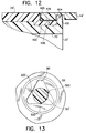
- FIG. 12 a partial cross-sectional view of an alternate embodiment is shown.
- the rear end of the ledge 78' of the shell 22' has an annular ring section 400, an annular recess 402, and the cover 24' has a reduced thickness at the recess 402.
- the battery cap 14' has an inner annular recess 404.
- the annular ring section 400 is received into the annular recess 404 to removably mechanically interlock the cap on the rear end of the housing.
- the inner surface 406 of the leading section 405 of the battery cap 14' makes a frictional and sealing engagement with the cover 24' at area 408.
- the leading section 405 is outwardly deformed in the mounted position shown in Figure 12. Thus, the leading section 405 compresses against the cover 24' at the area 408.
- other types of detent mounting systems could be provided.
- FIG 13 a partial top view of a cleaning attachment frame 86 similar to Figure 4D is shown with a cross-sectional view of the shaft 83' of an alternate embodiment in the aperture 90.
- the shaft 83' has a generally circular profile, but includes three detent sections 500.
- the detent sections 500 make an interference fit with side walls of the frame 86 in the aperture 90. This helps to prevent unintentional rotation of the frame 86 relative to the shaft 83'.
Landscapes
- Engineering & Computer Science (AREA)
- General Engineering & Computer Science (AREA)
- Mechanical Engineering (AREA)
- Brushes (AREA)
Applications Claiming Priority (2)
| Application Number | Priority Date | Filing Date | Title |
|---|---|---|---|
| US639661 | 1996-04-29 | ||
| US08/639,661 US5697115A (en) | 1996-04-29 | 1996-04-29 | Cleaning apparatus with triangular shaped mount for attachment and quick disconnect |
Publications (2)
| Publication Number | Publication Date |
|---|---|
| EP0806170A2 true EP0806170A2 (de) | 1997-11-12 |
| EP0806170A3 EP0806170A3 (de) | 1998-02-04 |
Family
ID=24565044
Family Applications (1)
| Application Number | Title | Priority Date | Filing Date |
|---|---|---|---|
| EP97302901A Withdrawn EP0806170A3 (de) | 1996-04-29 | 1997-04-28 | Reinigungsgerät mit einer dreieckförmigen Befestigungsvorrichtung zur Kopplung und schnellen Entkopplung |
Country Status (8)
| Country | Link |
|---|---|
| US (1) | US5697115A (de) |
| EP (1) | EP0806170A3 (de) |
| JP (1) | JPH1043107A (de) |
| CN (1) | CN1148148C (de) |
| AU (1) | AU724177B2 (de) |
| BR (1) | BR9700626A (de) |
| CA (1) | CA2203345A1 (de) |
| MX (1) | MX9703086A (de) |
Cited By (3)
| Publication number | Priority date | Publication date | Assignee | Title |
|---|---|---|---|---|
| FR2781537A1 (fr) * | 1998-07-15 | 2000-01-28 | Claas Selbstfahr Erntemasch | Accouplement a crabots a autocentrage |
| GB2368006A (en) * | 2000-10-17 | 2002-04-24 | Kevin Hardinge | Cleaning pad |
| EP2815676A4 (de) * | 2012-02-16 | 2015-10-21 | Amorepacific Corp | Hautwaschmaschine mit einem bürstenlosen gleichstrommotor, steuerungsverfahren dafür und programmaufzeichnungsmedium zur durchführung des verfahrens |
Families Citing this family (56)
| Publication number | Priority date | Publication date | Assignee | Title |
|---|---|---|---|---|
| JP2002512312A (ja) | 1998-02-20 | 2002-04-23 | ザ、プロクター、エンド、ギャンブル、カンパニー | 音波または超音波を使用する衣類の染除去製品 |
| ES2217778T3 (es) | 1998-02-20 | 2004-11-01 | THE PROCTER & GAMBLE COMPANY | Producto para eliminar manchas de alfombras que usa ondas sonicas o ultrasonicas. |
| EP1131397B1 (de) | 1998-11-16 | 2004-07-21 | The Procter & Gamble Company | Reinigungsprodukt, welches schall- oder ultraschallwellen verwendet |
| ES2241673T3 (es) * | 1999-11-16 | 2005-11-01 | THE PROCTER & GAMBLE COMPANY | Procedimiento de limpieza que usa ondas ultrasonicas. |
| AU1613701A (en) * | 1999-11-16 | 2001-05-30 | Procter & Gamble Company, The | Ultrasonic cleaning |
| DE60026160T2 (de) * | 1999-11-16 | 2006-11-16 | The Procter & Gamble Company, Cincinnati | Reinigungsverfahren welches ultraschallwellen verwendet |
| JP2003513797A (ja) * | 1999-11-16 | 2003-04-15 | ザ、プロクター、エンド、ギャンブル、カンパニー | 超音波器具 |
| US6295681B1 (en) * | 1999-12-21 | 2001-10-02 | Olga H. Dolah | Rotary brush cleaning device |
| US6640377B2 (en) | 2000-03-28 | 2003-11-04 | Dedication To Detail, Inc. | Quick release buffing pad assembly |
| US6349446B1 (en) | 2000-03-28 | 2002-02-26 | Dedication To Detail, Inc. | Quick release buffing pad assembly |
| US7004182B2 (en) * | 2001-10-18 | 2006-02-28 | The Procter & Gamble Company | Enhanced ultrasonic cleaning devices |
| US20030084916A1 (en) * | 2001-10-18 | 2003-05-08 | Sonia Gaaloul | Ultrasonic cleaning products comprising cleaning composition having dissolved gas |
| US7313838B2 (en) * | 2002-12-03 | 2008-01-01 | S.C. Johnson & Son, Inc. | Powered cleaner/polisher |
| US7320691B2 (en) * | 2003-01-15 | 2008-01-22 | Pacific Bioscience Laboratories, Inc. | Apparatus and method for acoustic/mechanical treatment of early stage acne |
| WO2004064567A2 (en) * | 2003-01-16 | 2004-08-05 | Conair Corporation | Hand-held buffing device |
| CA2515848A1 (en) * | 2003-02-13 | 2004-09-02 | Black & Decker Inc. | Hand held scrubbing tool |
| US7325696B2 (en) * | 2003-10-29 | 2008-02-05 | Custom Accessories, Inc. | Multiple part adjustable automotive clothes rod assembly |
| US7631386B1 (en) | 2003-11-14 | 2009-12-15 | Bissell Homecare, Inc. | Compact carpet spot cleaner |
| US7565712B2 (en) * | 2003-11-26 | 2009-07-28 | S.C. Johnson & Son, Inc. | Powered cleaner/polisher |
| USD505263S1 (en) | 2004-03-19 | 2005-05-24 | Bissell Homecare, Inc. | Hand-held cleaning tool |
| US20050278879A1 (en) * | 2004-06-21 | 2005-12-22 | Jens Schnabel | Automatic "bird dropping remover" "BDR" a multi-purpose battery driven portible bird dropping cleaning system |
| US7386906B2 (en) * | 2004-06-22 | 2008-06-17 | Pacific Bioscience Laboratories, Inc. | Oscillating brushhead attachment system for a personal care appliance |
| US7414337B2 (en) * | 2005-03-14 | 2008-08-19 | Black & Decker Inc. | Scrubber |
| USD526100S1 (en) | 2005-05-05 | 2006-08-01 | Black & Decker Inc. | Hand-held scrubber |
| US7937792B2 (en) | 2006-10-19 | 2011-05-10 | Black & Decker Inc. | Pole scrubber |
| WO2008079944A2 (en) * | 2006-12-21 | 2008-07-03 | Minuteman International, Inc. | Brush mount for floor scrubber |
| JP3183618U (ja) * | 2012-03-22 | 2013-05-30 | 三菱化学株式会社 | 画像形成装置用の回転部材、画像形成カートリッジおよび画像形成装置 |
| GB2531176B (en) | 2013-03-15 | 2017-10-18 | Bissell Homecare Inc | Fluid delivery system |
| US9387578B2 (en) | 2013-10-28 | 2016-07-12 | Black & Decker Inc. | Handle arrangement for sander |
| WO2015138212A1 (en) | 2014-03-11 | 2015-09-17 | Michael Todd Lp | Personal care appliance |
| US10058351B2 (en) | 2015-03-19 | 2018-08-28 | Michael Todd Beauty Lp | Personal care appliance |
| US10632589B2 (en) | 2016-08-29 | 2020-04-28 | Black & Decker Inc. | Power tool |
| USD817645S1 (en) * | 2016-12-20 | 2018-05-15 | Ideavillage Products Corporation | Water-dispensing shower brush |
| USD821758S1 (en) * | 2016-12-20 | 2018-07-03 | Ideavillage Products Corp. | Water-dispensing shower brush |
| CN107125913A (zh) * | 2017-06-26 | 2017-09-05 | 苏州迈晧电器有限公司 | 一种多功能电动旋转刷 |
| CN110279221B (zh) * | 2019-03-15 | 2021-08-06 | 木里木外家具启东有限公司 | 一种便于清洁的智能餐桌 |
| USD959150S1 (en) | 2020-03-04 | 2022-08-02 | Church & Dwight Co., Inc. | Combination skincare cleansing brush and cradle |
| CN111557617B (zh) * | 2020-06-08 | 2021-09-03 | 苏州高之仙自动化科技有限公司 | 换垫装置、地面石材护理机及换垫方法 |
| US12178311B2 (en) | 2020-11-03 | 2024-12-31 | Techtronic Cordless Gp | Drive coupler for power scrubber |
| CN112428124B (zh) * | 2020-11-06 | 2022-03-04 | 上海高仙自动化科技发展有限公司 | 一种工作头及石材护理机器人 |
| US11751585B1 (en) | 2022-05-13 | 2023-09-12 | Sharkninja Operating Llc | Flavored beverage carbonation system |
| US12213617B2 (en) | 2022-05-13 | 2025-02-04 | Sharkninja Operating Llc | Flavored beverage carbonation process |
| US12096880B2 (en) | 2022-05-13 | 2024-09-24 | Sharkninja Operating Llc | Flavorant for beverage carbonation system |
| US11647860B1 (en) | 2022-05-13 | 2023-05-16 | Sharkninja Operating Llc | Flavored beverage carbonation system |
| US12539500B2 (en) | 2022-08-31 | 2026-02-03 | Sharkninja Operating Llc | Additive containers |
| US12084334B2 (en) | 2022-11-17 | 2024-09-10 | Sharkninja Operating Llc | Ingredient container |
| US11738988B1 (en) | 2022-11-17 | 2023-08-29 | Sharkninja Operating Llc | Ingredient container valve control |
| US11745996B1 (en) | 2022-11-17 | 2023-09-05 | Sharkninja Operating Llc | Ingredient containers for use with beverage dispensers |
| US12103840B2 (en) | 2022-11-17 | 2024-10-01 | Sharkninja Operating Llc | Ingredient container with sealing valve |
| US11634314B1 (en) | 2022-11-17 | 2023-04-25 | Sharkninja Operating Llc | Dosing accuracy |
| USD1091308S1 (en) | 2022-12-23 | 2025-09-02 | Sharkninja Operating Llc | Ingredient container |
| USD1092208S1 (en) | 2022-12-23 | 2025-09-09 | Sharkninja Operating Llc | Cap of ingredient container |
| US11925287B1 (en) | 2023-03-22 | 2024-03-12 | Sharkninja Operating Llc | Additive container with inlet tube |
| US11871867B1 (en) | 2023-03-22 | 2024-01-16 | Sharkninja Operating Llc | Additive container with bottom cover |
| US12116257B1 (en) | 2023-03-22 | 2024-10-15 | Sharkninja Operating Llc | Adapter for beverage dispenser |
| USD1048611S1 (en) | 2024-01-18 | 2024-10-22 | Davinci Ii Csj, Llc | Scrubber |
Family Cites Families (55)
| Publication number | Priority date | Publication date | Assignee | Title |
|---|---|---|---|---|
| CA519315A (en) * | 1955-12-13 | C. Arf Myron | Electric shoe polisher | |
| US2733465A (en) * | 1956-02-07 | Floor maintenance machine having | ||
| US931327A (en) * | 1908-03-13 | 1909-08-17 | Mary A Manzel | Drill-chuck. |
| US1138926A (en) * | 1913-01-06 | 1915-05-11 | William B Thayer | Frictional coupling. |
| US1119392A (en) * | 1913-08-28 | 1914-12-01 | William B Thayer | Floor-polishing apparatus. |
| US1373206A (en) * | 1919-11-06 | 1921-03-29 | Laurence P Sharples | Flexible spindle-coupling |
| US2337402A (en) * | 1942-08-12 | 1943-12-21 | Cons Vultee Aircraft Corp | Drill chuck |
| US2561279A (en) * | 1945-07-27 | 1951-07-17 | William E Holt | Floor maintenance machine |
| US2527256A (en) * | 1947-11-07 | 1950-10-24 | Earle R Jackson | Connector for brushes, brooms, and the like |
| US2799035A (en) * | 1953-06-04 | 1957-07-16 | Charles L Pfluger | Tools for roughening surfaces |
| US2849736A (en) * | 1955-05-16 | 1958-09-02 | Albert G Kohle | Fabric steaming and brushing device |
| US3162876A (en) * | 1962-12-14 | 1964-12-29 | Ronson Corp | Coupling arrangement for polishing machine |
| US3251086A (en) * | 1964-07-21 | 1966-05-17 | Gen Electric | Power handle assembly |
| US3289231A (en) * | 1965-03-02 | 1966-12-06 | Iona Mfg Company Inc | Electric shoe polisher |
| US3343192A (en) * | 1966-01-28 | 1967-09-26 | Goldstein Morton | Power operated cleaning device |
| US3417417A (en) * | 1966-04-18 | 1968-12-24 | Louise K. Rhodes | Scrubbing implement |
| US3396417A (en) * | 1966-09-12 | 1968-08-13 | Richard A. Starr | Window washer |
| US3423781A (en) * | 1967-10-25 | 1969-01-28 | Harry H Henson | Securement for mop or broom heads |
| US3600735A (en) * | 1970-01-26 | 1971-08-24 | Dustbane Enterprises Ltd | Floor polisher drive connection |
| US3734548A (en) * | 1971-12-20 | 1973-05-22 | K Tel International | Shaft connection mechanism |
| USD245948S (en) | 1976-01-12 | 1977-10-04 | Sperry Rand Corporation | Facial cleaning apparatus |
| USD245883S (en) | 1976-04-26 | 1977-09-27 | North American Philips Corporation | Electric complexion brush |
| USD250228S (en) | 1977-07-01 | 1978-11-14 | Sunbeam Corporation | Electrical facial brush |
| US4158246A (en) * | 1977-09-07 | 1979-06-19 | Disston, Inc. | Portable cordless scrubber |
| USD262257S (en) | 1978-09-18 | 1981-12-15 | Seymour Sohn | Combined electric pot scrubber and holder therefor |
| USD259076S (en) | 1978-10-10 | 1981-05-05 | Doyel John S | Battery-operated brush and scrubber |
| US4168560A (en) * | 1978-10-12 | 1979-09-25 | Doyel John S | Battery-driven cleaning device |
| USD263998S (en) | 1979-03-13 | 1982-04-20 | Braun Ag | Body massage appliance |
| USD257747S (en) | 1979-05-29 | 1981-01-06 | Clairol Incorporated | Skin treatment tool |
| US4476602A (en) * | 1982-08-13 | 1984-10-16 | Black & Decker, Inc. | Portable electric scrubber |
| USD281035S (en) | 1983-10-25 | 1985-10-22 | Ronald Herzfeld | Brush |
| USD286706S (en) | 1984-04-02 | 1986-11-18 | Black & Decker, Inc. | Cordless shoe polisher |
| USD290551S (en) | 1984-07-11 | 1987-06-30 | Fairform Manufacturing Company Limited | Battery-operated brush holder |
| USD290550S (en) | 1984-11-09 | 1987-06-30 | North American Philips Corporation | Handle for a shoe-polishing accessory or the like |
| USD301398S (en) | 1985-09-30 | 1989-06-06 | Cheung Henry C H | Shoe polishing set |
| DE3615918A1 (de) * | 1986-05-12 | 1987-11-19 | Eckart Mayer | Manuell handhabbare reinigungsvorrichtung |
| USD300185S (en) | 1986-08-11 | 1989-03-14 | Sanyei Electric Co. (HK) Ltd. | Shoe polisher |
| USD305480S (en) | 1987-01-23 | 1990-01-16 | John Manufacturing Limited | Power driven shoe brush |
| USD313890S (en) | 1987-04-17 | 1991-01-22 | Machuron Robert M | Electric scrubbing brush |
| US4866804A (en) * | 1987-10-16 | 1989-09-19 | Tennant Trend, Inc. | Quick connect/disconnect for a surface cleaning machine |
| DE8715181U1 (de) * | 1987-10-17 | 1987-12-03 | Ledermann Gmbh + Co, 7240 Horb | Spannvorrichtung |
| GB2217927B (en) * | 1988-03-12 | 1992-04-01 | Electronic Components Ltd | Bayonet coupling connector |
| FR2628488B1 (fr) * | 1988-03-14 | 1990-12-28 | Ecia Equip Composants Ind Auto | Attache rapide du type a baionnette perfectionnee |
| US4984339A (en) * | 1988-10-20 | 1991-01-15 | Velcro Industries B.V. | Hook for hook and loop fasteners |
| USD321596S (en) | 1989-02-13 | 1991-11-19 | King Imports, Inc. | Shoe polish applicator |
| US5026223A (en) * | 1990-12-20 | 1991-06-25 | Gte Valenite Corporation | Bayonet tool locking device |
| US5138735A (en) * | 1991-03-18 | 1992-08-18 | Safety-Kleen Corporation | Buffing pad and attachment system therefor |
| US5289605A (en) * | 1991-12-10 | 1994-03-01 | Armbruster Joseph M | DC powered scrubber |
| US5201100A (en) * | 1992-06-15 | 1993-04-13 | Velcro Industries B.V. | Adjustable device for hook and loop fastener |
| FR2694053B1 (fr) * | 1992-07-24 | 1994-09-02 | Souriau & Cie | Ensemble de connexion à verrouillage du type baïonnette. |
| US5261140A (en) * | 1992-08-14 | 1993-11-16 | Szymanski Thomas A | Reversible rotary shampoo machine or floor waxer |
| US5495632A (en) * | 1993-05-03 | 1996-03-05 | Baker; Rhonda | Motorized hand held scrubber |
| USD352828S (en) | 1993-08-02 | 1994-11-29 | Chin-Hei Chen | Electric shoes shiner |
| US5421053A (en) * | 1994-04-28 | 1995-06-06 | Aar Corp. | Removable brush coupling |
| US5551114A (en) * | 1995-06-20 | 1996-09-03 | Lee; Tao-Pan | Shoeshine assembly |
-
1996
- 1996-04-29 US US08/639,661 patent/US5697115A/en not_active Expired - Lifetime
-
1997
- 1997-04-22 CA CA002203345A patent/CA2203345A1/en not_active Abandoned
- 1997-04-23 AU AU19029/97A patent/AU724177B2/en not_active Ceased
- 1997-04-28 JP JP9111461A patent/JPH1043107A/ja not_active Withdrawn
- 1997-04-28 EP EP97302901A patent/EP0806170A3/de not_active Withdrawn
- 1997-04-28 MX MX9703086A patent/MX9703086A/es not_active IP Right Cessation
- 1997-04-29 CN CNB971132399A patent/CN1148148C/zh not_active Expired - Fee Related
- 1997-04-29 BR BR9700626A patent/BR9700626A/pt not_active Application Discontinuation
Cited By (4)
| Publication number | Priority date | Publication date | Assignee | Title |
|---|---|---|---|---|
| FR2781537A1 (fr) * | 1998-07-15 | 2000-01-28 | Claas Selbstfahr Erntemasch | Accouplement a crabots a autocentrage |
| GB2368006A (en) * | 2000-10-17 | 2002-04-24 | Kevin Hardinge | Cleaning pad |
| GB2368006B (en) * | 2000-10-17 | 2004-12-01 | Kevin Hardinge | Cleaning pad for use with hand-held rotary driven equipment |
| EP2815676A4 (de) * | 2012-02-16 | 2015-10-21 | Amorepacific Corp | Hautwaschmaschine mit einem bürstenlosen gleichstrommotor, steuerungsverfahren dafür und programmaufzeichnungsmedium zur durchführung des verfahrens |
Also Published As
| Publication number | Publication date |
|---|---|
| BR9700626A (pt) | 1998-09-29 |
| JPH1043107A (ja) | 1998-02-17 |
| AU1902997A (en) | 1997-11-06 |
| EP0806170A3 (de) | 1998-02-04 |
| CN1171918A (zh) | 1998-02-04 |
| AU724177B2 (en) | 2000-09-14 |
| MX9703086A (es) | 1998-04-30 |
| US5697115A (en) | 1997-12-16 |
| CA2203345A1 (en) | 1997-10-29 |
| CN1148148C (zh) | 2004-05-05 |
Similar Documents
| Publication | Publication Date | Title |
|---|---|---|
| US5697115A (en) | Cleaning apparatus with triangular shaped mount for attachment and quick disconnect | |
| US6248007B1 (en) | Hand held motorized tool with over-molded cover | |
| US5956792A (en) | Hand held motorized cleaning apparatus with linear, orbital and/or dual motion | |
| US5978999A (en) | Motorized scrub brush with multiple hand holding positions | |
| MXPA97003086A (en) | Cleaning equipment with a formatriangular support for a device and disconnectionrap | |
| US5706541A (en) | Watertight friction fit battery cap with cam removal | |
| EP3675701B1 (de) | Staubsaugerwerkzeug mit einem drehbaren kanal zum bewegen zwischen einer gebrauchsposition und einer aufbewahrungsposition an einem staubsauger | |
| EP1603428B1 (de) | Tragbare schrubbvorrichtung | |
| US7543348B2 (en) | Bottle cleaning device and methods of operation | |
| EP3894149B1 (de) | Anordnung einer schnappverschlussantriebskappe | |
| CN116407032A (zh) | 清洁机构及清洁设备 | |
| CN217162017U (zh) | 清洁机构及清洁设备 | |
| CN219846356U (zh) | 一种地刷及清洁设备 | |
| EP3932278A1 (de) | Bodenbürste und staubsauger | |
| CN219720582U (zh) | 一种地刷及清洁设备 | |
| MXPA97003087A (en) | Brush for motorized cleaning with multip manual retention positions | |
| CN220694643U (zh) | 除尘刷 | |
| MXPA97003088A (en) | Manual motorized tool with a molded cover | |
| EP0990402A2 (de) | Tragbares elektrisches Reinigungswerkzeug | |
| CN210446893U (zh) | 清洁工具 | |
| CN223392379U (zh) | 一种擦窗机器人 | |
| CN222194901U (zh) | 用于清洗的电动工具 | |
| CN219720577U (zh) | 清洁设备及清洁头 | |
| CN210676258U (zh) | 一种水晶玻璃盒的清洁装置 | |
| CN218943034U (zh) | 一种煎烤机 |
Legal Events
| Date | Code | Title | Description |
|---|---|---|---|
| PUAI | Public reference made under article 153(3) epc to a published international application that has entered the european phase |
Free format text: ORIGINAL CODE: 0009012 |
|
| AK | Designated contracting states |
Kind code of ref document: A2 Designated state(s): DE DK FI FR GB IT NL SE |
|
| PUAL | Search report despatched |
Free format text: ORIGINAL CODE: 0009013 |
|
| AK | Designated contracting states |
Kind code of ref document: A3 Designated state(s): DE DK FI FR GB IT NL SE |
|
| STAA | Information on the status of an ep patent application or granted ep patent |
Free format text: STATUS: THE APPLICATION IS DEEMED TO BE WITHDRAWN |
|
| 18D | Application deemed to be withdrawn |
Effective date: 19980805 |