EP0805916B1 - Procede de travail en continu avec compression isotherme au maximum pour des moteurs thermiques a piston rotatif - Google Patents
Procede de travail en continu avec compression isotherme au maximum pour des moteurs thermiques a piston rotatif Download PDFInfo
- Publication number
- EP0805916B1 EP0805916B1 EP96901732A EP96901732A EP0805916B1 EP 0805916 B1 EP0805916 B1 EP 0805916B1 EP 96901732 A EP96901732 A EP 96901732A EP 96901732 A EP96901732 A EP 96901732A EP 0805916 B1 EP0805916 B1 EP 0805916B1
- Authority
- EP
- European Patent Office
- Prior art keywords
- chambers
- working
- rotary piston
- operating mode
- compression
- Prior art date
- Legal status (The legal status is an assumption and is not a legal conclusion. Google has not performed a legal analysis and makes no representation as to the accuracy of the status listed.)
- Expired - Lifetime
Links
- 230000006835 compression Effects 0.000 title claims description 25
- 238000007906 compression Methods 0.000 title claims description 25
- 238000002485 combustion reaction Methods 0.000 claims description 17
- 238000000034 method Methods 0.000 claims description 12
- 239000000446 fuel Substances 0.000 claims description 4
- 238000001816 cooling Methods 0.000 claims description 3
- 239000007789 gas Substances 0.000 description 21
- 230000001419 dependent effect Effects 0.000 description 2
- 230000001737 promoting effect Effects 0.000 description 2
- FNYLWPVRPXGIIP-UHFFFAOYSA-N Triamterene Chemical compound NC1=NC2=NC(N)=NC(N)=C2N=C1C1=CC=CC=C1 FNYLWPVRPXGIIP-UHFFFAOYSA-N 0.000 description 1
- QVGXLLKOCUKJST-UHFFFAOYSA-N atomic oxygen Chemical compound [O] QVGXLLKOCUKJST-UHFFFAOYSA-N 0.000 description 1
- TZCXTZWJZNENPQ-UHFFFAOYSA-L barium sulfate Chemical compound [Ba+2].[O-]S([O-])(=O)=O TZCXTZWJZNENPQ-UHFFFAOYSA-L 0.000 description 1
- 238000006243 chemical reaction Methods 0.000 description 1
- 125000004122 cyclic group Chemical group 0.000 description 1
- 238000010586 diagram Methods 0.000 description 1
- 239000012530 fluid Substances 0.000 description 1
- 238000010438 heat treatment Methods 0.000 description 1
- 238000002347 injection Methods 0.000 description 1
- 239000007924 injection Substances 0.000 description 1
- 239000003350 kerosene Substances 0.000 description 1
- 239000000203 mixture Substances 0.000 description 1
- 239000001301 oxygen Substances 0.000 description 1
- 229910052760 oxygen Inorganic materials 0.000 description 1
Images

Classifications
-
- F—MECHANICAL ENGINEERING; LIGHTING; HEATING; WEAPONS; BLASTING
- F02—COMBUSTION ENGINES; HOT-GAS OR COMBUSTION-PRODUCT ENGINE PLANTS
- F02B—INTERNAL-COMBUSTION PISTON ENGINES; COMBUSTION ENGINES IN GENERAL
- F02B53/00—Internal-combustion aspects of rotary-piston or oscillating-piston engines
- F02B53/04—Charge admission or combustion-gas discharge
- F02B53/08—Charging, e.g. by means of rotary-piston pump
-
- F—MECHANICAL ENGINEERING; LIGHTING; HEATING; WEAPONS; BLASTING
- F02—COMBUSTION ENGINES; HOT-GAS OR COMBUSTION-PRODUCT ENGINE PLANTS
- F02B—INTERNAL-COMBUSTION PISTON ENGINES; COMBUSTION ENGINES IN GENERAL
- F02B75/00—Other engines
- F02B75/02—Engines characterised by their cycles, e.g. six-stroke
-
- Y—GENERAL TAGGING OF NEW TECHNOLOGICAL DEVELOPMENTS; GENERAL TAGGING OF CROSS-SECTIONAL TECHNOLOGIES SPANNING OVER SEVERAL SECTIONS OF THE IPC; TECHNICAL SUBJECTS COVERED BY FORMER USPC CROSS-REFERENCE ART COLLECTIONS [XRACs] AND DIGESTS
- Y02—TECHNOLOGIES OR APPLICATIONS FOR MITIGATION OR ADAPTATION AGAINST CLIMATE CHANGE
- Y02T—CLIMATE CHANGE MITIGATION TECHNOLOGIES RELATED TO TRANSPORTATION
- Y02T10/00—Road transport of goods or passengers
- Y02T10/10—Internal combustion engine [ICE] based vehicles
- Y02T10/12—Improving ICE efficiencies
Definitions
- the invention relates to a continuous Working methods for heat engines, in particular for rotary piston heat engines, with steady Promotion and multi-stage compression of the working gas and a rotary piston heat engine for Implementation of the working process.
- the working gas already has one of after compression high temperature dependent on the compression level.
- Gas temperature can be increased even further.
- This too high Working temperature can be followed by adiabatic Relaxation not completely dismantled and in progress being transformed.
- the excess heat is with the hot exhaust gas discharged to the environment. You can also Piston engines not without this high temperature Endure forced cooling.
- the object of the invention is a working method of to improve the type mentioned in such a way that at a high thermal efficiency Working heat largely in mechanical work is converted, as well as a structurally simple Device for carrying out the working process create that ensures a high level of economy and also as a small machine with changing ones High working pressure and constant speed Efficiency achieved.
- a Rotary piston heat engine with one Ring cylinder, the interior of which is covered by a rotor Disc piston and one fixed in the ring cylinder helical abutments divided into working chambers is that through inlet and outlet openings through lines are interconnected to carry out the Working procedure is created in that Air cooler (intercooler) for isothermal compression and an external combustion chamber for one Constant pressure combustion are provided.
- the continuously operating rotary piston motor includes essentially a continuously promoting, multi-stage with compressing the lowest possible temperature Rotary piston compressor and one about twice as much large hot air motor. The heating of the compressed working gas to enlarge the Gas volume and work done in an external Combustion chamber through uninterrupted constant pressure combustion.
- the compressed working gas can also be used Air heater or heat exchanger through external combustion or concentrated solar heat.
- the engine can be started with compressed air under load and reaches a high one even at low speed Torque, which is due to the good degree of filling Maximum speed continues.
- the engine can operate in push mode through throttle valves in the outlet openings of the Relaxation chambers are braked extremely effectively.
- the internal combustion engine works very environmentally friendly. He sucks in its working air evenly and quietly, burns simple, additive-free fuel continuously with multiple excess air at relative low pressure, and the clean exhaust gas flows evenly and quietly outside.
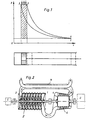
- the improvement in thermal efficiency is based that the working gas according to Fig. 1 is as isothermal is compressed by 1-2. It is during the multi-stage compression by intensive cooling Prevents increase in gas temperature, but no heat dissipated higher temperature.
- the compressed working gas which ideally has ambient temperature becomes Isobaric expansion of 2-3 is only heated to such an extent that it at the adiabatic relaxation of 3-4 again Ambient temperature cools down.
- Fig. 1 The hatched area in Fig. 1 represents the Working methods represent usable work.
- the centrifugal compressor 5 is powered by a turbine 6 driven in the heated in an air heater 7 Air is released.
- Flow machines reach however only as large, multi-stage machines and only with high ones Speed an economically high working pressure and Efficiency.
- Rotary piston machines also reach as small machines have a high working pressure and Efficiency that is constant with changing speed stay.
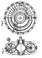
- the inlet and outlet openings of the ten are continuous promotional working chambers a, b, c, d, e through lines connected in such a way that three large working chambers a (Compression chambers) air over air cooler in two promote smaller working chambers b (compression chambers), which converts the compressed working air into an air cooler promote smaller working chamber c.
- compression chambers three large working chambers a
- compression chambers three large working chambers a
- compression chambers compression chambers
- compressed working air into an air cooler promote smaller working chamber c.
- the Delivery ratio of the large working chambers to the small working chamber gives the compression ratio the approximately isothermal compression 1-2 (Fig. 5).
- the small working chamber c promotes the compacted Working air as cool as possible via an external combustion chamber in two small working chambers d (expansion chambers).
- the combustion chamber with flame tube becomes simple fuel like kerosene continuously after a single ignition constant pressure with multiple excess air burned in an environmentally friendly way.
- the two smaller working chambers d become hot Compressed gas in two large working chambers e (Relaxation chambers) in which it is directed Ambient pressure and relaxed to ambient temperature.
- the one generated by adiabatic relaxation 3-4 Work must be done to compress the working air will.
- Through throttle valves in the outlet openings of the The machine can accommodate large relaxation chambers Push operation are braked extremely effectively.
- the compressed working air can be heated using Air heater also by external combustion or concentrated solar heat.
- the system can be closed Cyclic operated and to a multiple higher Power can be charged (Fig. 6).
- the two large relaxation chambers e first Serve compression chambers.
Landscapes
- Engineering & Computer Science (AREA)
- Chemical & Material Sciences (AREA)
- Combustion & Propulsion (AREA)
- Mechanical Engineering (AREA)
- General Engineering & Computer Science (AREA)
- Engine Equipment That Uses Special Cycles (AREA)
Claims (15)
- Procédé de travail en continu pour des moteurs thermiques, en particulier des moteurs thermiques à piston rotatif, avec transport stabilisé et compression étagée du gaz moteur,
caractérisé en ce que le gaz moteur est soumis à une compression au moins approximativement isothermique (1-2), soumis à une expansion isobare (2-3) et soumis à une détente adiabatique (3-4). - Procédé de travail selon la revendication 1,
caractérisé en ce que la compression (1-2) est effectuée en deux étages avec refroidissement pendant la compression. - Procédé de travail selon la revendication 1 ou 2,
caractérisé en ce que la compression (1-2) est effectuée à la température ambiante. - Procédé de travail selon la revendication 3,
caractérisé en ce qu'on amène au gaz moteur, pendant l'expansion isobare (2-3), exactement autant de chaleur que nécessaire pour que sa température, pendant la détente adiabatique (3-4), tombe à la température ambiante. - Procédé de travail selon l'une des revendications précédentes,
caractérisé en ce que l'amenée de chaleur est effectuée par combustion d'un carburant dans une chambre de combustion. - Procédé de travail selon l'une des revendications 1 à 4,
caractérisé en ce que l'amenée de chaleur est effectuée, au moyen d'un réchauffeur d'air, par combustion externe ou chaleur solaire concentrée. - Procédé de travail selon la revendication 6,
caractérisé en ce que le procédé de travail effectue un cycle fermé. - Moteur thermique à piston rotatif pour la mise en oeuvre du procédé de travail selon l'une des revendications précédentes, avec un cylindre annulaire dont le volume interne est divisé en chambres de travail (a, b, c, d, e), par un rotor à piston plat et une butée hélicoïdale fixée dans le cylindre annulaire, qui sont reliées les unes aux autres, par l'intermédiaire d'ouvertures d'admission et d'échappement, par des conduites,
caractérisé en ce que sont prévus un refroidisseur d'air (refroidisseur intermédiaire) pour la compression isothermique et une chambre de combustion externe pour une combustion à pression constante. - Moteur thermique à piston rotatif selon la revendication 8,
caractérisé en ce qu'il comprend dix chambres de travail (a, a, a, b, b, c, d, d, e, e). - Moteur thermique à piston rotatif selon la revendication 8 ou 9,
caractérisé en ce que les chambres de travail sont reliées les unes aux autres de telle manière que le gaz moteur peut être transporté depuis trois grandes chambres de compression (a), par l'intermédiaire de refroidisseurs d'air, dans deux petites chambres de compression (b). - Moteur thermique à piston rotatif selon la revendication 10,
caractérisé en ce que les chambres de travail sont reliées les unes aux autres de telle manière que le gaz moteur peut être transporté, depuis les deux petites chambres de compression (b), par l'intermédiaire de refroidisseurs d'air, dans une chambre de travail (c), la chambre de travail (c) étant plus petite que les petites chambres de compression (b). - Moteur thermique à piston rotatif selon la revendication 11,
caractérisé en ce que des vannes anti-retour sont disposées dans les ouvertures d'échappement des chambres de compression (a, b). - Moteur thermique à piston rotatif selon la revendication 11 ou 12,
caractérisé en ce que les chambres de travail sont reliées les unes aux autres de telle manière que le gaz moteur peut être transporté, depuis la chambre de travail (c), par l'intermédiaire d'une chambre de combustion externe, dans deux chambres de dilatation (d), les chambres de dilatation (d) étant plus grandes que la chambre de travail (c). - Moteur thermique à piston rotatif selon la revendication 13,
caractérisé en ce que les chambres de travail sont reliées les unes aux autres de telle manière que le gaz moteur peut être transporté, depuis les deux chambres de dilatation (d), dans deux chambres de détente (e), les chambres de détente (e) étant plus grandes que les chambres de dilatation (d). - Moteur thermique à piston rotatif selon la revendication 14,
caractérisé en ce que des vannes d'étranglement sont disposées dans les ouvertures d'échappement des chambres de détente (e).
Applications Claiming Priority (3)
| Application Number | Priority Date | Filing Date | Title |
|---|---|---|---|
| DE19501189A DE19501189A1 (de) | 1995-01-17 | 1995-01-17 | Kontinuierliches Arbeitsverfahren mit möglichst isothermer Verdichtung für Rotationskolben-Wärmekraftmaschinen |
| DE19501189 | 1995-01-17 | ||
| PCT/EP1996/000112 WO1996022456A1 (fr) | 1995-01-17 | 1996-01-12 | Procede de travail en continu avec compression isotherme au maximum pour des moteurs thermiques a piston rotatif |
Publications (2)
| Publication Number | Publication Date |
|---|---|
| EP0805916A1 EP0805916A1 (fr) | 1997-11-12 |
| EP0805916B1 true EP0805916B1 (fr) | 1998-06-10 |
Family
ID=7751644
Family Applications (1)
| Application Number | Title | Priority Date | Filing Date |
|---|---|---|---|
| EP96901732A Expired - Lifetime EP0805916B1 (fr) | 1995-01-17 | 1996-01-12 | Procede de travail en continu avec compression isotherme au maximum pour des moteurs thermiques a piston rotatif |
Country Status (4)
| Country | Link |
|---|---|
| EP (1) | EP0805916B1 (fr) |
| AU (1) | AU4619796A (fr) |
| DE (2) | DE19501189A1 (fr) |
| WO (1) | WO1996022456A1 (fr) |
Family Cites Families (6)
| Publication number | Priority date | Publication date | Assignee | Title |
|---|---|---|---|---|
| US1704254A (en) * | 1926-05-15 | 1929-03-05 | Jaffe John | Motor |
| DE2002141A1 (de) * | 1970-01-19 | 1971-07-29 | Weber Hans Dr Ing | Verfahren und Motor zur und fuer Gleichdruck-Verbrennung |
| US3918414A (en) * | 1971-03-15 | 1975-11-11 | Benjamin F Hughes | Rotary motor |
| DE2213519C3 (de) * | 1972-03-20 | 1974-08-29 | Oskar 8722 Schraudenbach Hart | Kontinuierlich arbeitende Rotationskolben-Brennkraftmaschine |
| JPS55125322A (en) * | 1979-03-17 | 1980-09-27 | Isamu Nemoto | Thermodynamic cycle for performing regenerative heat exchange and double acting internal combustion engine for such cycle |
| JPS57188728A (en) * | 1981-05-18 | 1982-11-19 | Mitsubishi Motors Corp | Compression ignition type internal combustion engine |
-
1995
- 1995-01-17 DE DE19501189A patent/DE19501189A1/de not_active Ceased
-
1996
- 1996-01-12 AU AU46197/96A patent/AU4619796A/en not_active Abandoned
- 1996-01-12 WO PCT/EP1996/000112 patent/WO1996022456A1/fr not_active Ceased
- 1996-01-12 EP EP96901732A patent/EP0805916B1/fr not_active Expired - Lifetime
- 1996-01-12 DE DE59600277T patent/DE59600277D1/de not_active Expired - Fee Related
Also Published As
| Publication number | Publication date |
|---|---|
| WO1996022456A1 (fr) | 1996-07-25 |
| EP0805916A1 (fr) | 1997-11-12 |
| DE19501189A1 (de) | 1996-07-18 |
| DE59600277D1 (de) | 1998-07-16 |
| AU4619796A (en) | 1996-08-07 |
Similar Documents
| Publication | Publication Date | Title |
|---|---|---|
| CN108561229A (zh) | 发电机系统以及用于产生电能的方法 | |
| EP0805916B1 (fr) | Procede de travail en continu avec compression isotherme au maximum pour des moteurs thermiques a piston rotatif | |
| DE2524620A1 (de) | Kreiskolbenbrennkraftmaschine | |
| DE803388C (de) | Freikolben-Treibgaserzeuger | |
| DE2743149A1 (de) | Verbrennungsmotor | |
| DE102017105613A1 (de) | Kolbenmaschine und Kreisprozessvorrichtung | |
| DE4300264A1 (de) | Verfahren und Vorrichtung zur Energieumsetzung mit Drehkolbenaggregaten | |
| WO1992012335A1 (fr) | Dispositif de suralimentation d'un moteur a combustion interne | |
| DE19625449A1 (de) | Kombi-Verbundverfahren für Dieselmotoren | |
| DE861848C (de) | Dampferzeuger mit aufgeladenem Feuerraum | |
| DE3841876A1 (de) | Waermekraftmaschine | |
| DE804149C (de) | Arbeitsverfahren fuer Waermekraftanlagen und Waermekraftanlage | |
| DE886827C (de) | Freikolben-Brennkraftmaschine | |
| DE3447459A1 (de) | Gasgeschmierte kolbenmaschine | |
| DE102011017248B4 (de) | Freikolbenmaschine und Verfahren zu ihrem Betrieb | |
| DE639867C (de) | Mehrstufige Brennkraftturbine in Zweiflussbauart fuer Betrieb mit zerstaeubten oder gasfoermigen Treibstoffen | |
| DE660359C (de) | Einrichtung zur Inbetriebsetzung von Anlagen, bei denen zur Leistungserhoehung hohe Druecke verwendet werden, die durch gasturbinengetriebene Verdichter geliefert werden | |
| DE19818368C2 (de) | Verfahren zum Betreiben eines Triebwerks und Triebwerk | |
| DE893652C (de) | Verfahren zur Verdichtung gas- oder dampffoermiger Stoffe durch Waermezufuhr und Einrichtung zur Durchfuehrung des Verfahrens | |
| CH96539A (de) | Wärmekraftmaschine. | |
| DE19902004A1 (de) | Dampfdruckmotor mit Abgaseinspeisung | |
| WO2007042022A2 (fr) | Moteur a combustion interne | |
| WO1999020883A1 (fr) | Moteur a combustion interne a combustion continue | |
| DE4219080A1 (de) | Wärmekraftmaschine nach dem Verdrängungsprinzip mit getrennten Einrichtungen für Kompression und Expansion sowie Wärmetauschern zur Verringerung der Verluste | |
| DE19734984A1 (de) | Verfahren zur Kompression von Gasen |
Legal Events
| Date | Code | Title | Description |
|---|---|---|---|
| PUAI | Public reference made under article 153(3) epc to a published international application that has entered the european phase |
Free format text: ORIGINAL CODE: 0009012 |
|
| 17P | Request for examination filed |
Effective date: 19970708 |
|
| AK | Designated contracting states |
Kind code of ref document: A1 Designated state(s): DE FR GB IT SE |
|
| GRAG | Despatch of communication of intention to grant |
Free format text: ORIGINAL CODE: EPIDOS AGRA |
|
| GRAG | Despatch of communication of intention to grant |
Free format text: ORIGINAL CODE: EPIDOS AGRA |
|
| GRAH | Despatch of communication of intention to grant a patent |
Free format text: ORIGINAL CODE: EPIDOS IGRA |
|
| 17Q | First examination report despatched |
Effective date: 19971121 |
|
| GRAH | Despatch of communication of intention to grant a patent |
Free format text: ORIGINAL CODE: EPIDOS IGRA |
|
| GRAA | (expected) grant |
Free format text: ORIGINAL CODE: 0009210 |
|
| AK | Designated contracting states |
Kind code of ref document: B1 Designated state(s): DE FR GB IT SE |
|
| PG25 | Lapsed in a contracting state [announced via postgrant information from national office to epo] |
Ref country code: IT Free format text: LAPSE BECAUSE OF FAILURE TO SUBMIT A TRANSLATION OF THE DESCRIPTION OR TO PAY THE FEE WITHIN THE PRESCRIBED TIME-LIMIT;WARNING: LAPSES OF ITALIAN PATENTS WITH EFFECTIVE DATE BEFORE 2007 MAY HAVE OCCURRED AT ANY TIME BEFORE 2007. THE CORRECT EFFECTIVE DATE MAY BE DIFFERENT FROM THE ONE RECORDED. Effective date: 19980610 |
|
| GBT | Gb: translation of ep patent filed (gb section 77(6)(a)/1977) |
Effective date: 19980611 |
|
| ET | Fr: translation filed | ||
| REF | Corresponds to: |
Ref document number: 59600277 Country of ref document: DE Date of ref document: 19980716 |
|
| PG25 | Lapsed in a contracting state [announced via postgrant information from national office to epo] |
Ref country code: SE Free format text: LAPSE BECAUSE OF FAILURE TO SUBMIT A TRANSLATION OF THE DESCRIPTION OR TO PAY THE FEE WITHIN THE PRESCRIBED TIME-LIMIT Effective date: 19980910 |
|
| PLBE | No opposition filed within time limit |
Free format text: ORIGINAL CODE: 0009261 |
|
| STAA | Information on the status of an ep patent application or granted ep patent |
Free format text: STATUS: NO OPPOSITION FILED WITHIN TIME LIMIT |
|
| 26N | No opposition filed | ||
| PGFP | Annual fee paid to national office [announced via postgrant information from national office to epo] |
Ref country code: FR Payment date: 20011218 Year of fee payment: 7 |
|
| REG | Reference to a national code |
Ref country code: GB Ref legal event code: IF02 |
|
| PGFP | Annual fee paid to national office [announced via postgrant information from national office to epo] |
Ref country code: GB Payment date: 20020104 Year of fee payment: 7 |
|
| PGFP | Annual fee paid to national office [announced via postgrant information from national office to epo] |
Ref country code: DE Payment date: 20020315 Year of fee payment: 7 |
|
| PG25 | Lapsed in a contracting state [announced via postgrant information from national office to epo] |
Ref country code: GB Free format text: LAPSE BECAUSE OF NON-PAYMENT OF DUE FEES Effective date: 20030112 |
|
| PG25 | Lapsed in a contracting state [announced via postgrant information from national office to epo] |
Ref country code: DE Free format text: LAPSE BECAUSE OF NON-PAYMENT OF DUE FEES Effective date: 20030801 |
|
| GBPC | Gb: european patent ceased through non-payment of renewal fee | ||
| PG25 | Lapsed in a contracting state [announced via postgrant information from national office to epo] |
Ref country code: FR Free format text: LAPSE BECAUSE OF NON-PAYMENT OF DUE FEES Effective date: 20030930 |
|
| REG | Reference to a national code |
Ref country code: FR Ref legal event code: ST |