EP0805328A2 - Strömungsmodul - Google Patents
Strömungsmodul Download PDFInfo
- Publication number
- EP0805328A2 EP0805328A2 EP97105472A EP97105472A EP0805328A2 EP 0805328 A2 EP0805328 A2 EP 0805328A2 EP 97105472 A EP97105472 A EP 97105472A EP 97105472 A EP97105472 A EP 97105472A EP 0805328 A2 EP0805328 A2 EP 0805328A2
- Authority
- EP
- European Patent Office
- Prior art keywords
- plate elements
- module according
- flow module
- flow
- plate
- Prior art date
- Legal status (The legal status is an assumption and is not a legal conclusion. Google has not performed a legal analysis and makes no representation as to the accuracy of the status listed.)
- Granted
Links
Images


Classifications
-
- F—MECHANICAL ENGINEERING; LIGHTING; HEATING; WEAPONS; BLASTING
- F28—HEAT EXCHANGE IN GENERAL
- F28F—DETAILS OF HEAT-EXCHANGE AND HEAT-TRANSFER APPARATUS, OF GENERAL APPLICATION
- F28F3/00—Plate-like or laminated elements; Assemblies of plate-like or laminated elements
- F28F3/02—Elements or assemblies thereof with means for increasing heat-transfer area, e.g. with fins, with recesses, with corrugations
- F28F3/04—Elements or assemblies thereof with means for increasing heat-transfer area, e.g. with fins, with recesses, with corrugations the means being integral with the element
- F28F3/048—Elements or assemblies thereof with means for increasing heat-transfer area, e.g. with fins, with recesses, with corrugations the means being integral with the element in the form of ribs integral with the element or local variations in thickness of the element, e.g. grooves, microchannels
-
- B—PERFORMING OPERATIONS; TRANSPORTING
- B01—PHYSICAL OR CHEMICAL PROCESSES OR APPARATUS IN GENERAL
- B01J—CHEMICAL OR PHYSICAL PROCESSES, e.g. CATALYSIS OR COLLOID CHEMISTRY; THEIR RELEVANT APPARATUS
- B01J10/00—Chemical processes in general for reacting liquid with gaseous media other than in the presence of solid particles, or apparatus specially adapted therefor
- B01J10/007—Chemical processes in general for reacting liquid with gaseous media other than in the presence of solid particles, or apparatus specially adapted therefor in the presence of catalytically active bodies, e.g. porous plates
-
- B—PERFORMING OPERATIONS; TRANSPORTING
- B01—PHYSICAL OR CHEMICAL PROCESSES OR APPARATUS IN GENERAL
- B01J—CHEMICAL OR PHYSICAL PROCESSES, e.g. CATALYSIS OR COLLOID CHEMISTRY; THEIR RELEVANT APPARATUS
- B01J12/00—Chemical processes in general for reacting gaseous media with gaseous media; Apparatus specially adapted therefor
- B01J12/007—Chemical processes in general for reacting gaseous media with gaseous media; Apparatus specially adapted therefor in the presence of catalytically active bodies, e.g. porous plates
-
- B—PERFORMING OPERATIONS; TRANSPORTING
- B01—PHYSICAL OR CHEMICAL PROCESSES OR APPARATUS IN GENERAL
- B01J—CHEMICAL OR PHYSICAL PROCESSES, e.g. CATALYSIS OR COLLOID CHEMISTRY; THEIR RELEVANT APPARATUS
- B01J14/00—Chemical processes in general for reacting liquids with liquids; Apparatus specially adapted therefor
- B01J14/005—Chemical processes in general for reacting liquids with liquids; Apparatus specially adapted therefor in the presence of catalytically active bodies, e.g. porous plates
-
- B—PERFORMING OPERATIONS; TRANSPORTING
- B01—PHYSICAL OR CHEMICAL PROCESSES OR APPARATUS IN GENERAL
- B01J—CHEMICAL OR PHYSICAL PROCESSES, e.g. CATALYSIS OR COLLOID CHEMISTRY; THEIR RELEVANT APPARATUS
- B01J15/00—Chemical processes in general for reacting gaseous media with non-particulate solids, e.g. sheet material; Apparatus specially adapted therefor
- B01J15/005—Chemical processes in general for reacting gaseous media with non-particulate solids, e.g. sheet material; Apparatus specially adapted therefor in the presence of catalytically active bodies, e.g. porous plates
-
- B—PERFORMING OPERATIONS; TRANSPORTING
- B01—PHYSICAL OR CHEMICAL PROCESSES OR APPARATUS IN GENERAL
- B01J—CHEMICAL OR PHYSICAL PROCESSES, e.g. CATALYSIS OR COLLOID CHEMISTRY; THEIR RELEVANT APPARATUS
- B01J16/00—Chemical processes in general for reacting liquids with non- particulate solids, e.g. sheet material; Apparatus specially adapted therefor
- B01J16/005—Chemical processes in general for reacting liquids with non- particulate solids, e.g. sheet material; Apparatus specially adapted therefor in the presence of catalytically active bodies, e.g. porous plates
-
- B—PERFORMING OPERATIONS; TRANSPORTING
- B01—PHYSICAL OR CHEMICAL PROCESSES OR APPARATUS IN GENERAL
- B01J—CHEMICAL OR PHYSICAL PROCESSES, e.g. CATALYSIS OR COLLOID CHEMISTRY; THEIR RELEVANT APPARATUS
- B01J19/00—Chemical, physical or physico-chemical processes in general; Their relevant apparatus
- B01J19/24—Stationary reactors without moving elements inside
- B01J19/2475—Membrane reactors
-
- B—PERFORMING OPERATIONS; TRANSPORTING
- B01—PHYSICAL OR CHEMICAL PROCESSES OR APPARATUS IN GENERAL
- B01J—CHEMICAL OR PHYSICAL PROCESSES, e.g. CATALYSIS OR COLLOID CHEMISTRY; THEIR RELEVANT APPARATUS
- B01J19/00—Chemical, physical or physico-chemical processes in general; Their relevant apparatus
- B01J19/24—Stationary reactors without moving elements inside
- B01J19/248—Reactors comprising multiple separated flow channels
- B01J19/249—Plate-type reactors
-
- B—PERFORMING OPERATIONS; TRANSPORTING
- B01—PHYSICAL OR CHEMICAL PROCESSES OR APPARATUS IN GENERAL
- B01J—CHEMICAL OR PHYSICAL PROCESSES, e.g. CATALYSIS OR COLLOID CHEMISTRY; THEIR RELEVANT APPARATUS
- B01J4/00—Feed or outlet devices; Feed or outlet control devices
- B01J4/04—Feed or outlet devices; Feed or outlet control devices using osmotic pressure using membranes, porous plates
-
- F—MECHANICAL ENGINEERING; LIGHTING; HEATING; WEAPONS; BLASTING
- F28—HEAT EXCHANGE IN GENERAL
- F28D—HEAT-EXCHANGE APPARATUS, NOT PROVIDED FOR IN ANOTHER SUBCLASS, IN WHICH THE HEAT-EXCHANGE MEDIA DO NOT COME INTO DIRECT CONTACT
- F28D21/00—Heat-exchange apparatus not covered by any of the groups F28D1/00 - F28D20/00
- F28D21/0015—Heat and mass exchangers, e.g. with permeable walls
-
- F—MECHANICAL ENGINEERING; LIGHTING; HEATING; WEAPONS; BLASTING
- F28—HEAT EXCHANGE IN GENERAL
- F28D—HEAT-EXCHANGE APPARATUS, NOT PROVIDED FOR IN ANOTHER SUBCLASS, IN WHICH THE HEAT-EXCHANGE MEDIA DO NOT COME INTO DIRECT CONTACT
- F28D9/00—Heat-exchange apparatus having stationary plate-like or laminated conduit assemblies for both heat-exchange media, the media being in contact with different sides of a conduit wall
- F28D9/0062—Heat-exchange apparatus having stationary plate-like or laminated conduit assemblies for both heat-exchange media, the media being in contact with different sides of a conduit wall the conduits for one heat-exchange medium being formed by spaced plates with inserted elements
- F28D9/0075—Heat-exchange apparatus having stationary plate-like or laminated conduit assemblies for both heat-exchange media, the media being in contact with different sides of a conduit wall the conduits for one heat-exchange medium being formed by spaced plates with inserted elements the plates having openings therein for circulation of the heat-exchange medium from one conduit to another
-
- F—MECHANICAL ENGINEERING; LIGHTING; HEATING; WEAPONS; BLASTING
- F28—HEAT EXCHANGE IN GENERAL
- F28F—DETAILS OF HEAT-EXCHANGE AND HEAT-TRANSFER APPARATUS, OF GENERAL APPLICATION
- F28F3/00—Plate-like or laminated elements; Assemblies of plate-like or laminated elements
- F28F3/08—Elements constructed for building-up into stacks, e.g. capable of being taken apart for cleaning
- F28F3/083—Elements constructed for building-up into stacks, e.g. capable of being taken apart for cleaning capable of being taken apart
-
- B—PERFORMING OPERATIONS; TRANSPORTING
- B01—PHYSICAL OR CHEMICAL PROCESSES OR APPARATUS IN GENERAL
- B01J—CHEMICAL OR PHYSICAL PROCESSES, e.g. CATALYSIS OR COLLOID CHEMISTRY; THEIR RELEVANT APPARATUS
- B01J2219/00—Chemical, physical or physico-chemical processes in general; Their relevant apparatus
- B01J2219/00002—Chemical plants
- B01J2219/00018—Construction aspects
- B01J2219/0002—Plants assembled from modules joined together
-
- B—PERFORMING OPERATIONS; TRANSPORTING
- B01—PHYSICAL OR CHEMICAL PROCESSES OR APPARATUS IN GENERAL
- B01J—CHEMICAL OR PHYSICAL PROCESSES, e.g. CATALYSIS OR COLLOID CHEMISTRY; THEIR RELEVANT APPARATUS
- B01J2219/00—Chemical, physical or physico-chemical processes in general; Their relevant apparatus
- B01J2219/00049—Controlling or regulating processes
- B01J2219/00051—Controlling the temperature
- B01J2219/00074—Controlling the temperature by indirect heating or cooling employing heat exchange fluids
- B01J2219/00076—Controlling the temperature by indirect heating or cooling employing heat exchange fluids with heat exchange elements inside the reactor
- B01J2219/00085—Plates; Jackets; Cylinders
-
- B—PERFORMING OPERATIONS; TRANSPORTING
- B01—PHYSICAL OR CHEMICAL PROCESSES OR APPARATUS IN GENERAL
- B01J—CHEMICAL OR PHYSICAL PROCESSES, e.g. CATALYSIS OR COLLOID CHEMISTRY; THEIR RELEVANT APPARATUS
- B01J2219/00—Chemical, physical or physico-chemical processes in general; Their relevant apparatus
- B01J2219/24—Stationary reactors without moving elements inside
- B01J2219/2401—Reactors comprising multiple separate flow channels
- B01J2219/245—Plate-type reactors
- B01J2219/2451—Geometry of the reactor
- B01J2219/2453—Plates arranged in parallel
-
- B—PERFORMING OPERATIONS; TRANSPORTING
- B01—PHYSICAL OR CHEMICAL PROCESSES OR APPARATUS IN GENERAL
- B01J—CHEMICAL OR PHYSICAL PROCESSES, e.g. CATALYSIS OR COLLOID CHEMISTRY; THEIR RELEVANT APPARATUS
- B01J2219/00—Chemical, physical or physico-chemical processes in general; Their relevant apparatus
- B01J2219/24—Stationary reactors without moving elements inside
- B01J2219/2401—Reactors comprising multiple separate flow channels
- B01J2219/245—Plate-type reactors
- B01J2219/2461—Heat exchange aspects
- B01J2219/2462—Heat exchange aspects the reactants being in indirect heat exchange with a non reacting heat exchange medium
-
- B—PERFORMING OPERATIONS; TRANSPORTING
- B01—PHYSICAL OR CHEMICAL PROCESSES OR APPARATUS IN GENERAL
- B01J—CHEMICAL OR PHYSICAL PROCESSES, e.g. CATALYSIS OR COLLOID CHEMISTRY; THEIR RELEVANT APPARATUS
- B01J2219/00—Chemical, physical or physico-chemical processes in general; Their relevant apparatus
- B01J2219/24—Stationary reactors without moving elements inside
- B01J2219/2401—Reactors comprising multiple separate flow channels
- B01J2219/245—Plate-type reactors
- B01J2219/2475—Separation means, e.g. membranes inside the reactor
-
- B—PERFORMING OPERATIONS; TRANSPORTING
- B01—PHYSICAL OR CHEMICAL PROCESSES OR APPARATUS IN GENERAL
- B01J—CHEMICAL OR PHYSICAL PROCESSES, e.g. CATALYSIS OR COLLOID CHEMISTRY; THEIR RELEVANT APPARATUS
- B01J2219/00—Chemical, physical or physico-chemical processes in general; Their relevant apparatus
- B01J2219/24—Stationary reactors without moving elements inside
- B01J2219/2401—Reactors comprising multiple separate flow channels
- B01J2219/245—Plate-type reactors
- B01J2219/2476—Construction materials
- B01J2219/2477—Construction materials of the catalysts
- B01J2219/2479—Catalysts coated on the surface of plates or inserts
-
- B—PERFORMING OPERATIONS; TRANSPORTING
- B01—PHYSICAL OR CHEMICAL PROCESSES OR APPARATUS IN GENERAL
- B01J—CHEMICAL OR PHYSICAL PROCESSES, e.g. CATALYSIS OR COLLOID CHEMISTRY; THEIR RELEVANT APPARATUS
- B01J2219/00—Chemical, physical or physico-chemical processes in general; Their relevant apparatus
- B01J2219/24—Stationary reactors without moving elements inside
- B01J2219/2401—Reactors comprising multiple separate flow channels
- B01J2219/245—Plate-type reactors
- B01J2219/2476—Construction materials
- B01J2219/2483—Construction materials of the plates
- B01J2219/2485—Metals or alloys
-
- B—PERFORMING OPERATIONS; TRANSPORTING
- B01—PHYSICAL OR CHEMICAL PROCESSES OR APPARATUS IN GENERAL
- B01J—CHEMICAL OR PHYSICAL PROCESSES, e.g. CATALYSIS OR COLLOID CHEMISTRY; THEIR RELEVANT APPARATUS
- B01J2219/00—Chemical, physical or physico-chemical processes in general; Their relevant apparatus
- B01J2219/24—Stationary reactors without moving elements inside
- B01J2219/2401—Reactors comprising multiple separate flow channels
- B01J2219/245—Plate-type reactors
- B01J2219/2491—Other constructional details
- B01J2219/2492—Assembling means
- B01J2219/2493—Means for assembling plates together, e.g. sealing means, screws, bolts
-
- Y—GENERAL TAGGING OF NEW TECHNOLOGICAL DEVELOPMENTS; GENERAL TAGGING OF CROSS-SECTIONAL TECHNOLOGIES SPANNING OVER SEVERAL SECTIONS OF THE IPC; TECHNICAL SUBJECTS COVERED BY FORMER USPC CROSS-REFERENCE ART COLLECTIONS [XRACs] AND DIGESTS
- Y10—TECHNICAL SUBJECTS COVERED BY FORMER USPC
- Y10S—TECHNICAL SUBJECTS COVERED BY FORMER USPC CROSS-REFERENCE ART COLLECTIONS [XRACs] AND DIGESTS
- Y10S165/00—Heat exchange
- Y10S165/355—Heat exchange having separate flow passage for two distinct fluids
- Y10S165/356—Plural plates forming a stack providing flow passages therein
- Y10S165/364—Plural plates forming a stack providing flow passages therein with fluid traversing passages formed through the plate
- Y10S165/365—Plural plates forming a stack providing flow passages therein with fluid traversing passages formed through the plate including peripheral seal element forming flow channel bounded by seal and heat exchange plates
- Y10S165/366—Rigid or semi-rigid peripheral seal frame
Definitions
- the invention relates to a flow module according to the preamble of claim 1.
- Such flow modules are e.g. used as a plate heat exchanger for the heat exchange of two fluids.
- the flow module instead of as a heat exchanger as a material exchanger (e.g. JP 1-230 991 A ) or as a reactor (one of the two fluids is made by coating individual plates with a reactive substance, for example brought into contact with a catalyst, the other fluid is used for temperature control of the reactor, for example DE 34 34 415 A1 ).
- a heat exchanger as a material exchanger
- a reactor one of the two fluids is made by coating individual plates with a reactive substance, for example brought into contact with a catalyst, the other fluid is used for temperature control of the reactor, for example DE 34 34 415 A1 ).
- JP 3-177 791 A A device with which the above-mentioned problems are solved is disclosed in JP 3-177 791 A.
- This device corresponds to the preamble of claim 1. It comprises, in particular, a straight, parallel profile, and the openings in the individual plate elements for the feed and discharge channels extend essentially over the entire area of the profile.
- Such a design of the openings for the supply and discharge channels is also known from DE-OS 15 01 617 .
- a disadvantage of these devices is that due to the described design of the openings for the supply and discharge channels, the longitudinal strips of the individual plate elements are pressed outwards under pressure. This can destroy the device. In particular, however, there is a risk of leaks since the seals arranged between the plate elements can be moved.
- the present invention is therefore based on the object of creating a flow module with which the stability of the valve even under pressure The device is retained without the flow properties in the plate inlet and plate outlet area being significantly impaired.
- the plate elements have a rectilinear, parallel profile, so that a flow space between two adjacent plate elements is formed as a plurality of rectilinear, parallel flow channels, and the openings for the supply and discharge channels of the two fluids extend essentially over the entire area of the profile, so that a pronounced feed and discharge space is formed.
- a plurality of webs for mechanical stabilization are arranged in the openings for the supply and discharge channels, the webs which are arranged in the inlet area or outlet area of the profiling ending in profiled plate elements below the surface of the plate element.
- the cross section of the supply or discharge channels is larger than the sum of the cross sections of the flow channels present between two adjacent plate elements.
- the flow module according to the invention can preferably, but not exclusively, be used as a heat exchanger, mass exchanger or reactor.
- the inventive design of the webs enables an improved supply of the flow channels, so that the entire area can be used for heat or material exchange. Lowering the Crossbars also cause mixing of the fluid components flowing between the individual crosspieces.
- the size and geometry of the feed and discharge space for the two fluids involved ensures that the substantial pressure drop in the profiled plate elements is almost uniform over the entire length of the parallel flow channels. This achieves almost maximum efficiency in terms of heat or material exchange per addition of energy as well as a very small construction volume and small mass, so that a minimum of investment costs is realized.
- the two fluids involved can be in both gaseous and liquid form.
- Elastomer seals are preferably used for the sealing of flow spaces and supply and discharge channels. These can be integrated in grooves (26) which run in the plate elements.
- the elastomer seals can advantageously be vulcanized or inserted or injected into the grooves.
- all other known sealing options can of course also be used, for example fixed connections produced by welding, soldering or adhesive bonding.
- the profiled plate elements are made of materials that have good thermal conductivity, such as Metals and graphite.
- very low processing costs can be achieved through the use of simple manufacturing processes such as punching the openings and embossing the profile.
- the use of graphite foils as plate elements that can be stamped very easily also allows the use of very aggressive fluids such as concentrated acids or alkalis.
- plate elements that are profiled on one or both sides can be used as a heat exchanger.
- a plate element that is smooth on both sides is used between profiled plate elements, ie without profiling over the entire plate element average.
- Another advantageous embodiment is achieved with the use of plate elements profiled exclusively on one side.
- both liquid and gaseous fluids can be used in this embodiment for the primary and secondary side of the heat exchanger. Gas / gas or gas / liquid heat exchangers are often required. The gas-side heat transfer determines the heat transfer. Due to the homogeneous flow distribution that is achieved with the arrangement according to the invention, high specific heat exchanger lines can be realized.
- every second plate element continuously allows a mass transfer between the two fluids involved too.
- these permeable plate elements can be designed as membranes or membrane combinations such as, for example, composite membranes.
- membrane modules a membrane that naturally has no profiling follows a plate element that is profiled on both sides and is impermeable to material. With this module different membrane processes such as membrane distillation, pervaporation, pertraction and microfiltration can be carried out.
- the homogeneous flow distribution of the fluids via the profiled plate element has a particularly advantageous effect on the separation performance of the membrane modules.
- the plate construction allows the installation of different membranes such as porous hydrophilic, porous hydrophobic, dense membranes, asymmetrical membranes and composite membranes.
- the flow module can be adapted to the respective application by adapting the plate element and the seal present on the plate elements with regard to shape and material as well as hardness of the seal and geometry of the profiled plate surface.
- the cross section of the fluid supply and discharge channels should be larger than the sum of the cross sections of the flow channels within a profiled plate element.
- both liquid and gaseous fluids can be used for permeate and feed.
- individual surfaces of plate elements are coated with a reactive material, for example a catalyst. These surfaces are selected such that exactly one of the two fluids comes into contact with the reactive material on its way through the flow module.
- the reactor can basically be used in the same way as in the version as a heat exchanger with plate elements profiled on one or both sides.
- a plate element that is not profiled on both sides is arranged between profiled plate elements.
- a further advantageous embodiment is achieved by plate elements which are only profiled on one side.
- the catalyst reacts with one of the fluids in the flow channels provided for this fluid (corresponds to the secondary side of the heat exchanger).
- the flow channels of the second fluid are free from the catalyst (corresponds to the secondary side of the heat exchanger).
- the second fluid is used to control the temperature of the reactor.
- the catalyst is applied to the plate elements which are arranged on the primary side, for example by a thermal coating process.
- the largest turnover takes place within the first third of the reactor.
- the predominant length of the reactor is required in order to convert the remaining reactants which have remained due to the insufficient homogeneous flow distribution.
- the flow distribution or the residence time spectrum of the reactants significantly influences the reactor size. Since a very homogeneous flow distribution is achieved with the design according to the invention, it is particularly suitable for use as a reactor.
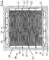
- Fig. 1 shows a first example of a device according to the invention in an exploded view, here designed as a heat exchanger.
- the device comprises a plurality of plate elements 1.1 - 1.3 (plate elements which have a profiling on at least one surface are also referred to below as flow plates) made of thermally conductive material, three of which are shown here.
- each of the three plate elements 1.1-1.3 has a one-sided profiling (the profiling itself is not shown in the figure), namely the profiling is in each case on the surface of the plate elements facing the viewer.
- This profiling forms flow channels for the fluids involved.
- the profiling is shown in detail in Fig. 2.
- flow spaces consisting of the individual flow channels of a profiled surface
- flow spaces between adjacent plate elements can alternate with be charged with a first and a second fluid.
- the first fluid flows between left 1.1 and middle 1.2 plate element, and between second 1.2 and right plate element 1.3 the second fluid. Beyond the right plate element 1.3, the first fluid etc. flows again.
- the feed and discharge channels for the two fluids are formed by openings 8, 9, 10, 11 that are aligned with one another at the edges of the plate elements 1.1 - 1.3.
- each of the four openings is provided with a plurality of webs 22 for mechanical stabilization.
- the two openings 10, 11 on the left and right edges are provided for the supply and discharge of the first fluid, and the two openings 8, 9 on the upper and lower edges for the supply and discharge of the second fluid.
- the flow channels from plate element to plate element are continuously rotated by 90 ° to one another.
- the two seals 5 are designed differently accordingly.
- the linear profile in the left 1.1 and right 1.3 plate elements runs parallel to the upper or lower edge and in the middle plate element 1.2 parallel to the left or right edge.
- the seals 5 used for realizing a reliable seal and for minimizing the production costs between two plate elements in each case are designed as circumferential seals which are integrated in a circumferential groove of a plate element surface.
- Prefabricated elastomer seals can be inserted into the sealing grooves.
- the use of elastomer seals enables their direct injection, so that a firm bond between the seal and the plate element arises. This considerably reduces the assembly effort.
- the supply and discharge channels are connected to external supply and discharge lines via flanges (not shown).
- the fluid In order to achieve the desired homogeneous flow distribution over the entire profiled area of the plate elements, the fluid must be routed through the outer supply and discharge lines with the lowest possible pressure loss and homogeneous flow distribution. This is achieved constructively through large flow cross sections in the area of the inlet and outlet channels of the flanges, in that the flanges have cutouts in the area of the inlet and outlet channels.
- a homogeneous flow guidance can be achieved by an intermediate plate which is arranged between the flange and the first plate element or the flange and the last plate element.
- a top view of a single, profiled plate element 1.4 as can be used in the flow module according to FIG. 1 but also in other versions of the device according to the invention (eg mass exchanger, reactor).
- the majority of the surface is occupied by the profiled area 20.
- the profiling forms rectilinear, parallel flow channels 30 (FIG. 4).
- the openings 8, 9, 10, 11 for the supply and discharge of the two fluids are arranged on the edges. Arranged in alignment one above the other, the openings 8, 9, 10, 11 form adjacent and superimposed flow plates of supply and discharge channels.
- the opening 10 for the supply of the first fluid is located on the right edge, the opening 11 for the removal of the first fluid is located on the opposite left edge.
- the first fluid flows through the flow channels shown in FIG Profiling.
- the openings extend along the edge of the plate element over the entire area of the profiling (transverse to the flow channels), so that a pronounced feed and discharge space for the fluid is formed.
- the opening 8 for the supply of the second fluid is located at the upper edge, and the opening for the removal of the second fluid is located on the opposite lower edge 9. This second fluid flows in the profile of the plate element adjacent to the plate element shown.
- the circumferential groove 26 seals supply and discharge channels to the outside and to the flow spaces between adjacent plate elements.
- the webs 22 according to the invention for mechanical stabilization are arranged in the openings for the feed and discharge spaces, since the fluid pressure in the feed and discharge channels tries to push the longitudinal strips 24 of the plate elements outwards.
- the webs are each arranged between the longitudinal strips 24 and the profiled area 20 of the plate element.
- the number of webs 22 and their width can be specifically adapted to the mechanical requirements.
- the surfaces of the webs which are arranged in the inlet area or outlet area of the profiling (here the webs in the openings 10 and 11) end somewhat below the profiled plate surface (approximately at the lower level of the profiling). This enables an improved supply of the flow channels in the web area in order to use the entire area for heat or material exchange.
- the structure of the webs 22 is shown in detail in FIG. 3.
- a variety of materials are possible for the flow plates. Plate designs made of metal, plastic or graphite have proven to be particularly advantageous with regard to performance data and production costs. These materials can be processed to produce the profiles and the grooves for the seals with simple and inexpensive manufacturing processes such as soft stamping / punching, injection molding, etc. Cutting processes are also possible.
- the profiled plate element 1.4 shown here has a rectangular base. This enables a homogeneous supply and discharge of the fluids through the openings without separate flow distributors. All flow channels on a plate surface are directly connected to the plate opening.
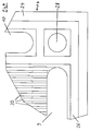
- FIG. 3 shows a sectional illustration of the plate element 1.4 according to FIG. 2 (section along the line AA in FIG. 2). It can be seen that the web 22 ends below the plate element surface 21, namely at the level of the bottom 31 of the channels 30. The surface 23 of the web 22 and the bottom 31 of the channels 30 thus merge seamlessly into one another.
- the reference numerals 24, 26, 11 denote the same components as in FIG. 2.
- FIG. 4 shows a detail of the plate element 1.4 according to FIG. 2.
- the flow channels 30 on the plate element surface can be seen, as well as the openings 10.9 for the supply of one fluid and the discharge of the other fluid.
- the circumferential groove 26 is provided for the integration of the circumferential seal.
- In the outer corner of the plate element there is a bore 28 for the tie rods with which the ones lying one above the other or next to one another Plate elements can be pressed together.
- Fig. 5 shows a further embodiment of the invention, which is designed as a heat exchanger.
- the two outer plate elements 1.6, 1.8 are now profiled on both surfaces, while the middle plate element 1.7 has a smooth surface on both sides and is designed as a dense film. Otherwise, this embodiment corresponds to that shown in FIG. 1.
- FIG. 6 shows an embodiment designed as a membrane module.
- Three plate elements 1.9-1.11 are shown, the two outer 1.9.1.11 being dense flow plates profiled on both sides.
- the middle plate element 1.10 is designed as a membrane, which enables a mass transfer of the two fluids adjacent to the membrane.
- a support plate 6 for supporting the adjacent seal 5 is arranged in each case in the inlet area and outlet area of the flow channels. This support plate 6 also prevents the membrane 1.10 from penetrating into the flow channels. In addition, a reliable seal is achieved by integrating the support plate.
- the three plate elements 1.12-1.14 shown are each profiled on one side, the profiling being present on the side facing the viewer.
- the profiled surfaces are coated with a catalyst, while the middle plate element 1.13 has no catalyst coating.
- the two outer plate elements 1.15, 1.17 are profiled on both sides, but have no catalyst coating.
- the middle plate element 1.16 is designed as a dense film, the side facing away from the viewer being coated with a catalyst. With this arrangement, only the fluid (reactant), which is located between the middle 1.16 and right 1.17 plate element and on this side of the left plate element 1.15, comes into contact with the catalyst, while the other fluid (heat transfer medium), which is between left 1.15 and middle 1.16 Plate module and located beyond the right plate element 1.17, has no contact with the catalyst.
Landscapes
- Chemical & Material Sciences (AREA)
- Engineering & Computer Science (AREA)
- Organic Chemistry (AREA)
- Chemical Kinetics & Catalysis (AREA)
- Physics & Mathematics (AREA)
- Thermal Sciences (AREA)
- Mechanical Engineering (AREA)
- General Engineering & Computer Science (AREA)
- Heat-Exchange Devices With Radiators And Conduit Assemblies (AREA)
- Cooling Or The Like Of Semiconductors Or Solid State Devices (AREA)
- Physical Or Chemical Processes And Apparatus (AREA)
Abstract
Description
- Die Erfindung betrifft ein Strömungsmodul nach dem Oberbegriff des Anspruch 1. Derartige Strömungsmodule werden z.B. als Plattenwärmetauscher für den Wärmeaustausch zweier Fluide benutzt.
- Bekannte Strömungsmodule in der Form von Plattenwärmetauschern wie z.B. in der EP 0 578 933 A1, EP 0 203 213 A1 und EP 0 487 931 A1 beschrieben, versuchen durch aufwendige Strukturen der Profilierung im Platteneinlauf- und Plattenauslaufbereich eine homogene Strömung über den Plattenbereich zu erreichen. Diese Platteneinlauf- und Plattenauslaufprofilierungen weisen folgende Nachteile auf:
- Der wesentliche Druckabfall erfolgt über einen kleinen Teil der Wärmeaustauschenden Fläche im Platteneinlauf- und Plattenauslaufbereich und wird somit nicht effizient zur Realisierung einer möglichst starken Strömung über die ganze Platte eingesetzt.
- Es tritt ein hoher Druckabfall auf, der eine hohe Pumpleistung erfordert.
- Die Strömungsverteilung im Platteneinlauf- und Plattenauslaufbereich ist stark abhängig von der Strömungsgeschwindigkeit und verschlechtert sich erheblich mit zunehmender Strömungsgeschwindigkeit.
- Die gleichen Probleme treten auf, wenn das Strömungsmodul anstatt als Wärmetauscher als Stoffaustauscher (jede zweite Platte ist durchlässig für mindestens eines der beiden Fluide, z.B. JP 1-230 991 A) oder als Reaktor (eines der beiden Fluide wird durch Beschichtung einzelner Platten mit einem reaktiven Stoff, z.B. einem Katalysator in Kontakt gebracht, das andere Fluid dient zur Temperierung des Reaktors, z.B. DE 34 34 415 A1) verwendet wird. (Anmerkung: die bisher als "Platten" bezeichneten Gegenstände werden im folgenden verallgemeinernd als "Plattenelemente" bezeichnet).
- Eine Vorrichtung, mit dem die obengenannten Probleme gelöst werden, ist in der JP 3-177 791 A offenbart. Diese Vorrichtung entspricht dem Oberbegriff des Anspruchs 1. Sie umfaßt insbesondere eine geradlinig parallel ausgebildete Profilierung , und die Durchbrechungen in den einzelnen Plattenelementen für die Zu- und Abfuhrkanäle erstrecken sich im wesentlichen über den gesamten Bereich der Profilierung. Eine derartige Ausbildung der Durchbrechungen für die Zu- und Abfuhrkanäle ist darüberhinaus auch aus der DE-OS 15 01 617 bekannt.
- Nachteilig an diesen Vorrichtungen ist, daß aufgrund der beschriebenen Ausbildung der Durchbrechungen für die Zu- und Abfuhrkanäle die Längsleisten der einzelnen Plattenelemente unter Druckbetrieb nach außen gedrückt werden. Dies kann zur Zerstörung der Vorrichtung führen. Insbesondere aber besteht die Gefahr von Undichtigkeiten, da die zwischen den Plattenelementen angeordneten Dichtungen verschoben werden können.
- Der vorliegenden Erfindung liegt deshalb die Aufgabe zugrunde, ein Strömungsmodul zu schaffen, mit dem auch unter Druckbetrieb die Stabilität der Vorrichtung erhalten bleibt, ohne daß die Strömungseigenschaften im Platteneinlauf- und Plattenauslaufbereich wesentlich verschlechtert werden.
- Diese Aufgabe wird mit einer Vorrichtung nach Patentanspruch 1 gelöst. Vorteilhafte Ausbildungen sind Gegenstand weiterer Ansprüche.
- Die Plattenelemente weisen eine geradlinige parallele Profilierung auf, so daß ein Strömungsraum zwischen jeweils zwei benachbarten Plattenelementen als Mehrzahl geradliniger, paralleler Strömungskanäle ausgebildet ist, und die Durchbrechungen für die Zu- und Abfuhrkanäle der beiden Fluide erstrecken sich im wesentlichen über den gesamten Bereich der Profilierung, so daß ein ausgeprägter Zu- und Abführraum gebildet ist. In den Durchbrechungen für die Zu- und Abfuhrkanäle sind erfindungsgemäß mehrere Stege zur mechanischen Stabilisierung angeordnet, wobei in profilierten Plattenelementen diejenigen Stege, welche im Einlaufbereich oder Auslaufbereich der Profilierung angeordnet sind, unterhalb der Plattenelementoberfläche enden.
- In einer vorteilhaften Ausführung ist der Querschnitt der Zu- oder Abfuhrkanäle größer ist als die Summe der Querschnitte der zwischen zwei benachbarten Plattenelementen vorhandenen Strömungskanälen. Wie bereits erwähnt, kann das erfindungsgemäße Strömungsmodul bevorzugt, jedoch nicht ausschließlich, als Wärmetauscher, Stoffaustauscher oder Reaktor verwendet werden.
- Durch die erfindungsgemäße Ausbildung der Stege wird eine verbesserte Versorgung der Strömungskanäle ermöglicht, so daß die gesamte Fläche für den Wärme- oder Stoffaustausch genutzt werden kann. Die Absenkung der Stege bewirkt darüberhinaus eine Vermischung der zwischen den einzelnen Stegen fliessenden Fluidanteile.
- Durch die Größe und Geometrie des Zu- und Abführraums für die beiden beteiligten Fluide wird erreicht, daß der wesentliche Druckabfall in den profilierten Plattenelementen nahezu gleichmäßig über die ganze Länge der parallelen Strömungskanäle entsteht. Dadurch wird nahezu höchste Effizienz hinsichtlich Wärme- oder Stoffaustausch pro Energiezusatz sowie ein sehr geringes Bauvolumen und kleine Masse erreicht, so daß ein Minimum an Investitionskosten realisiert wird.
- Mit der erfindungsgemäßen Vorrichtung wird ein erhöhter flächenspezifischer Wärme- oder Stoffaustausch bei konstantem Fluiddruckabfall über die Plattenelemente erreicht, wobei die Gestehungskosten nicht erhöht werden müssen.
- Die beiden beteiligten Fluide können sowohl in gasförmiger als auch in flüssiger Form vorliegen.
- Für die Abdichtungen von Strömungsräumen und Zu- und Abfuhrkanälen werden bevorzugt Elastomerdichtungen verwendet. Diese können in Nuten (26), welche in den Plattenelementen verlaufen, integriert sein. Die Elastomerdichtungen können dabei in die Nuten vorteilhaft einvulkanisiert oder eingelegt oder eingespritzt werden. Neben den Elastomerdichtungen können natürlich auch alle sonstigen bekannten Dichtungsmöglichkeiten verwendet werden, z.B. durch Schweißen, Löten oder Kleben hergestellte feste Verbindungen.
- In dieser Ausführung werden die profilierten Plattenelemente aus Werkstoffen gefertigt, die eine gute Wärmeleitfähigkeit aufweisen, wie z.B. Metalle und Graphit. Hierbei können sehr geringe Bearbeitungskosten durch den Einsatz einfacher Fertigungsverfahren wie Stanzen der Durchbrechungen und Prägen der Profilierung erreicht werden. Insbesondere die Verwendung von Graphitfolien als Plattenelemente die sehr einfach geprägt werden können, erlaubt auch den Einsatz von sehr aggressiven Fluiden wie konzentrierte Säuren oder Laugen.
- Grundsätzlich können in der Ausführung als Wärmetauscher einseitig oder beidseitig profilierte Plattenelemente eingesetzt werden. Bei der Verwendung von beidseitig profilierten Plattenelementen werden jeweils zwischen profilierten Plattenelementen ein beidseitig glattes Plattenelement, d. h. ohne Profilierung über den ganzen Plattenelementdurchschnitt eingesetzt. Eine andere vorteilhafte Ausführung wird erreicht mit dem Einsatz von ausschließlich einseitig profilierten Plattenelementen.
Grundsätzlich können bei dieser Ausführungsform für die Primär- und Sekundärseite des Wärmetauschers sowohl flüssige als auch gasförmige Fluide eingesetzt werden. Häufig werden Gas/Gas- oder Gas/Flüssigwärmetauscher benötigt. Hierbei bestimmt der gasseitige Wärmeübergang den Wärmedurchgang. Durch die homogene Strömungsverteilung, die mit der erfindungsgemäßen Anordnung erzielt wird, können hohe spezifische Wärmetauscherleitungen realisiert werden. - In dieser Ausführung läßt fortlaufend jedes zweite Plattenelement einen Stoffaustausch zwischen den beiden beteiligten Fluide zu. Insbesondere können diese durchlässigen Plattenelemente als Membrane oder Membrankombinationen wie z.B. Composite Membranen ausgebildet sein. Man spricht dann von Membranmodulen. In dieser Ausführung folgt jeweils auf ein beidseitig profiliertes und stoffundurchlässiges Plattenelement eine Membran, die naturgemäß keine Profilierung aufweist.
Mit diesem Modul können unterschiedliche Membranprozesse wie z.B. Membrandestillation, Pervaporation, Pertraction und Mikrofiltration durchgeführt werden. Besonders vorteilhaft wirkt sich dabei die homogene Strömungsverteilung der Fluide über das profilierte Plattenelement auf die Trennleistung der Membranmodule aus. Die Plattenkonstruktion erlaubt den Einbau unterschiedlicher Membranen wie z.B. porös hydrophil, porös hydrophob, dichte Membranen, asymmetrische Membrane und Composite Membranen. Dabei kann durch Anpassung des Plattenelements, sowie der an den Plattenelementen vorhandenen Dichtung hinsichtlich Form und Werkstoff sowie Härte der Dichtung und Geometrie der profilierten Plattenoberfläche das Strömungsmodul an die jeweilige Anwendung angepaßt werden. Jedoch sollte zur Realisierung einer homogenen Strömungsverteilung über die gesamte Länge der Strömungskanäle (Idealfall Propfenströmung) der Querschnitt der Fluid zu- bzw. Abführkanäle größer sein als die Summe der Querschnitte der Strömungskanäle innerhalb eines profilierten Plattenelements.
Grundsätzlich können für Permeat und Feed sowohl flüssige als auch gasförmige Fluide eingesetzt werden. - In dieser Ausführung sind einzelne Oberflächen von Plattenelementen mit einem reaktiven Material, z.B. einem Katalysator beschichtet. Diese Oberflächen werden derart ausgewählt, daß genau eines der beiden Fluide auf seinem Weg durch das Strömungsmodul mit dem reaktiven Material in Kontakt kommt. Der Reaktor kann grundsätzlich analog wie in der Ausführung als Wärmetauscher mit einseitig oder beidseitig profilierten Plattenelementen eingesetzt werden. Bei der Verwendung von beidseitig profilierten Plattenelementen werden jeweils zwischen profilierten Plattenelementen ein beidseitig unprofiliertes (z.B. mit annähernd glatter Oberfläche) Plattenelement angeordnet. Eine weitere vorteilhafte Ausführung wird erreicht durch jeweils nur einseitig profilierten Plattenelemente.
Der Katalysator reagiert mit einem der Fluide in den für dieses Fluid vorgesehen Strömungskanäle (entspricht der Sekundärseite des Wärmetauschers). Die Strömungskanäle des zweiten Fluids jedoch sind frei von dem Katalysator (entspricht der Sekundärseite des Wärmetauschers). Das zweite Fluid dient zur Temperierung des Reaktors.
Der Katalysator wird auf die Plattenelemente, die primärseitig angeordnet sind, z.B durch ein thermisches Beschichtungsverfahren, aufgebracht.
Bei vielen Reaktoren findet der größte Umsatz innerhalb des ersten Drittels des Reaktors statt. Die überwiegende Reaktorlänge wird benötigt, um die restlichen Reaktanten, die aufgrund der ungenügenden homogenen Strömungsverteilung verblieben sind, umzusetzen. Die Strömungsverteilung bzw. das Verweilzeitspektrum der Reaktanten beeinflußt die Reaktorgröße wesentlich. Da mit der erfindungsgmäßen Ausbildung eine sehr homogene Strömungsverteilung erzielt wird, ist sie für den Einsatz als Reaktor besonders geeignet. - Ausführungsbeispiele der erfindungsgemäßen Vorrichtung werden anhand von Fig. näher erläutert. Es zeigen:
- Fig. 1
- ein erfindungsgemäßes Strömungsmodul, ausgebildet als Plattenwärmetauscher (explodiert)
- Fig. 2
- ein einzelnes Plattenelement mit profilierter Oberfläche
- Fig. 3
- eine Schnittdarstellung des Plattenelements nach Fig. 2 (Schnittlinie AA in Fig. 2)
- Fig. 4
- ein Detail aus Fig. 2
- Fig. 5
- ein erfindungsgemäßes Strömungsmodul, ausgebildet als Plattenwärmetauscher (explodiert)
- Fig. 6
- ein erfindungsgemäßes Strömungsmodul, ausgebildet als Stoffaustauscher (explodiert)
- Fig. 7,8
- jeweils ein erfindungsgemäßes Strömungsmodul, ausgebildet als Reaktor (explodiert).
- Fig. 1 zeigt ein erstes Beispiel für eine erfindungsgemäße Vorrichtung in Explosionsdarstellung, hier als Wärmetauscher ausgebildet. Die Vorrichtung umfaßt eine Mehrzahl von Plattenelementen 1.1 - 1.3 (Plattenelemente, die mindestens auf einer Oberfläche eine Profilierung aufweisen, werden im folgenden auch als Strömungsplatten bezeichnet) aus wärmeleitfähigem Material, von denen hier drei eingezeichnet sind. Im vorliegenden Fall weist jeder der drei Plattenelemente 1.1 -1.3 eine einseitige Profilierung auf (die Profilerung selbst ist in der Fig. nicht dargestellt), und zwar befindet sich die Profilierung jeweils auf der dem Betrachter zugewandten Oberfläche der Plattenelemente. Diese Profilierung bildet Strömungskanäle für die beteiligten Fluide. Die Profilierung ist im einzelnen in Fig. 2 dargestellt. Auf diese Weise werden jeweils zwischen den Oberflächen benachbarter Plattenelemente 1.1 und 1.2 bzw 1.2 und 1.3 Strömungsräume (bestehend aus den einzelnen Strömungskanälen einer profilierten Oberfläche) gebildet. Diese Strömungsräume zwischen benachbarten Plattenelementen können alternierend mit einem ersten und zweiten Fluid beschickt werden. So strömt z.B. zwischen linkem 1.1 und mittlerem 1.2 Plattenelement das erste Fluid, und zwischen mittleren 1.2 und rechten Plattenelement 1.3 das zweite Fluid. Jenseits des rechten Plattenelements 1.3 fließt dann wieder das erste Fluid usw..
Die Zu- und Abführkanäle für die beiden Fluide werden durch miteinander fluchtende Durchbrechungen 8,9,10,11 an den Rändern der Plattenelemente 1.1 - 1.3 gebildet. In der hier gezeigten Ausführung ist jede der vier Durchbrechungen jeweils mit mehreren Stegen 22 zur mechanischen Stabilisierung versehen. Die beiden Durchbrechungen 10,11 am linken bzw. rechten Rand sind für die Zu- und Abfuhr des ersten Fluids vorgesehen, und die beiden Durchbrechungen 8,9 am oberen bzw. unteren Rand für die Zu- und Abfuhr des zweiten Fluids. Entsprechend dieser Lage der Durchbrechungen für die Zu- und Abfuhr der beiden Fluide sind die Strömungskanäle von Plattenelement zu Plattenelement fortlaufend um 90o zueinander verdreht. Um die abwechselnde Beschickung mit Fluid 1 und Fluid 2 zu gewährleisten, sind die beiden Dichtungen 5 entsprechend unterschiedlich ausgebildet. Bei der hier dargestellten Anordnung von Dichtungen 5 und Plattenelementen 1.1 bis 1.3 verläuft die geradlinige Profilierung im linken 1.1 und rechten 1.3 Plattenelement parallel zur oberen oder unteren Kante und im mittleren Plattenelement 1.2 parallel zur linken oder rechten Kante.
Die zur Realisierung einer verläßlichen Dichtung sowie zur Minimierung der Gestehungskosten zwischen jeweils zwei Plattenelementen eingesetzten Dichtungen 5 sind jeweils als umlaufende Dichtungen ausgebildet, die in einer umlaufenden Nut einer Plattenelementoberfläche integriert wird. Dabei können vorgefertigte Elastomerdichtungen in die Dichtungsnuten eingelegt werden. Ferner ermöglicht die Verwendung von Elastomerdichtungen deren direkte Einspritzung, so daß ein fester Verbund zwischen Dichtung und Plattenelement entsteht. Dadurch wird der Montageaufwand erheblich vermindert. - Die Zu- und Abfuhrkanäle sind über nicht dargestellte Flansche mit äußeren Zu- und Abführleitungen verbunden. Um die angestrebte homogene Strömungsverteilung über den gesamten profilierten Bereich der Plattenelemente zu erreichen, muß die Fluidführung durch die äußeren Zu- und Abfuhrleitungen mit möglichst geringem Druckverlust und homogener Strömungsverteilung geschehen. Dies wird konstruktiv durch große Strömungsquerschnitte im Bereich der Zu- und Abführkanäle der Flansche erreicht, indem die Flansche im Bereich der Zu- und Abführkanäle Aussparungen aufweisen. Ferner kann eine homogene Strömungsführung durch eine Zwischenplatte erreicht werden, die zwischen Flansch und erstem Plattenelement bzw. Flansch und letztem Plattenelement angeordnet ist.
- Ein einzelnes, profiliertes Plattenelement 1.4, wie es in dem Strömungsmodul nach Fig. 1 aber auch in anderen Ausführungen der erfindungsgemäßen Vorrichtung (z.B. Stofftauscher, Reaktor) verwendet werden kann, zeigt Fig. 2 in Draufsicht. Der größte Teil der Oberfläche wird von dem profilierten Bereich 20 eingenommen. Die Profilierung bildet geradlinige, parallele Strömungskanäle 30 (Fig. 4). An den Rändern sind die Durchbrechungen 8,9,10,11 für die Zu- und Abfuhr der beiden Fluide angeordnet. Fluchtend übereinander angeordnet, bilden die Durchbrechungen 8,9,10,11 neben- oder übereinanderliegender Strömungsplatten Zu- und Abführkanäle. Am rechten Rand befindet sich die Durchbrechung 10 für die Zufuhr des ersten Fluids, an dem gegenüberliegenden linken Rand befindet sich die Durchbrechung 11 für die Abfuhr des ersten Fluids. Auf seinem Weg zwischen Zufuhrkanal und Abfuhrkanal strömt das erste Fluid durch die in der Fig. dargestellten Strömungskanäle der Profilierung. Die Durchbrechungen erstrecken sich entlang der Kantenläge des Plattenelements über den gesamten Bereich der Profilierung (quer zu den Strömungskanälen), so daß ein ausgeprägter Zu- und Abführraum für das Fluid gebildet wird.
Am oberen Rand befindet sich die Durchbrechung 8 für die Zufuhr des zweiten Fluids, und am gegenüberliegenden unteren Rand 9 befindet sich die Durchbrechung für die Abfuhr des zweiten Fluids. Dieses zweite Fluid strömt in der Profilierung der zu dem gezeigten Plattenelement benachbarten Plattenelement.
Die umlaufende Nut 26 sorgt für die Abdichtung von Zu- und Abfuhrkanälen nach außen sowie gegenüber den Strömungsräumen zwischen benachbarten Plattenelementen.
In den Durchbrechungen für die Zu- und Abfuhräume sind die erfindungsgemäßen Stege 22 zur mechanischen Stabilisierung angeordnet, da der Fluiddruck in den Zu- und Abfuhrkanälen versucht, die Längsleisten 24 der Plattenelemente nach außen zu drücken. Die Stege sind jeweils zwischen den Längsleisten 24 und dem profilierten Bereich 20 des Plattenelements angeordnet. Die Anzahl der Stege 22 und deren Breite kann spezifisch an die mechanischen Anforderungen angepaßt werden. Die Oberflächen der Stege, welche im Einlaufbereich oder Auslaufbereich der Profilierung angeordnet sind (hier also die Stege in den Durchbrechungen 10 und 11) enden etwas unterhalb der profilierten Plattenoberfläche (in etwa auf dem unteren Niveau der Profilierung). Dadurch kann eine verbesserte Versorgung der Strömungskanäle im Stegbereich ermöglicht werden, um die gesamte Fläche für den Wärme- oder Stoffaustausch zu nutzen. Diese Absenkung der Stege bewirkt darüberhinaus eine Vermischung der zwischen den einzelnen Stegen fliessenden Fluidanteile. Der Aufbau der Stege 22 ist im Detail in Fig. 3 dargestellt.
Für die Strömungsplatten ist eine Vielzahl von Werkstoffen möglich. Besonders vorteilhaft hinsichtlich Leistungsdaten und Gestehungskosten haben sich aber Plattenausführungen aus Metall, Kunststoff oder Graphit erwiesen. Diese Werkstoffe können zur Herstellung der Profilierung und der Nuten für die Dichtungen mit einfachen und kostengünstigen Fertigungsverfahren wie Weichprägen/Stanzen, Spritzgießen etc. bearbeitet werden. Möglich sind aber auch spanabhebende Verfahren.
Das dargestellte profilierte Plattenelement 1.4 ist hier von rechteckiger Grundfläche. Dies ermöglicht eine homogene Zu- und Abfuhr der Fluide über die Durchbrechungen ohne separate Strömungsverteiler. Dabei sind alle Strömungskanäle einer Plattenoberfläche direkt mit dem Plattendurchbruch verbunden. - Fig. 3 zeigt eine Schnittdarstellung des Plattenelements 1.4 nach Fig. 2 (Schnitt entlang der Linie AA in Fig. 2). Man erkennt, daß der Steg 22 unterhalb der Plattenelementoberfläche 21, nämlich auf dem Niveau des Bodens 31 der Kanäle 30, endet. Die Oberfläche 23 des Stegs 22 und der Boden 31 der Kanäle 30 gehen somit stufenlos ineinander über. Die Bezugszeichen 24, 26, 11 bezeichnen die gleichen Bauteile wie in Fig. 2.
- Fig. 4 zeigt ein Detail des Plattenelements 1.4 nach Fig. 2. Zu erkennen sind die Strömungskanäle 30 auf der Plattenelementoberfläche, sowie die Durchbrechungen 10,9 für die Zufuhr des einen Fluids und die Abfuhr des anderen Fluids. Die umlaufende Nut 26 ist für die Integration der umlaufenden Dichtung vorgesehen. In der äußeren Ecke des Plattenelements befindet sich eine Bohrung 28 für die Zuganker, mit denen die über- oder nebeneinanderliegenden Plattenelemente aneinandergepreßt werden können.
- Fig. 5 zeigt ein weiteres Ausführungsbeispiel der Erfindung, welches als Wärmetauscher ausgebildet ist. Anders als in Fig. 1 sind die beiden äußeren Plattenelemente 1.6,1.8 nun auf beiden Oberflächen profiliert, während das mittlere Plattenelement 1.7 beidseitig eine glatte Oberfläche aufweist und als dichte Folie ausgebildet ist. Im übrigen entspricht diese Ausführung der in Fig. 1 gezeigten.
- Fig. 6 zeigt eine als Membranmodul ausgebildete Ausführung. Dargestellt sind drei Plattenelemente 1.9 - 1.11, wobei die beiden äußeren 1.9,1.11 beidseitig profilierte, dichte Strömungsplatten sind. Das mittlere Plattenelement 1.10 ist als Membrane ausgebildet, die einen Stoffaustausch der beiden an die Membran angrenzenden Fluide ermöglicht.
Jeweils im Eintrittsbereich und Austrittsbereich der Strömungskanäle ist ein Stützblech 6 zur Abstützung der benachbarten Dichtung 5 angeordnet. Dieses Stützblech 6 verhindert außerdem ein Eindringen der Membran 1.10 in die Strömungskanäle. Zusätzlich wird durch die Integration des Stützblechs eine verläßliche Abdichtung erreicht. - Fig. 7 zeigt einen erfindungsgemäß ausgebildeten Reaktor. Die drei dargestellten Plattenelemente 1.12 - 1.14 sind jeweils einseitig profiliert, wobei die Profilierung auf der dem Betrachter zugewandten Seite vorhanden ist. Bei den beiden äußeren Plattenelementen 1.12, 1.14 sind die profilierten Oberflächen mit einem Katalysator beschichtet, während das mittlere Plattenelement 1.13 keine Katalysator-Beschichtung aufweist. Bei dieser Anordnung kommt also nur das Fluid (Reactant), welches sich zwischen mittlerem 1.13 und rechtem 1.14 Plattenelement sowie diesseits des linken Plattenelements 1.12 befindet, mit dem Katalysator in Kontakt, während das andere Fluid (Wärmeträger), das sich zwischen linkem 1.12 und mittlerem 1.13 Plattenelement sowie jenseits des rechten Plattenelements 1.14 befindet, keinen Kontakt mit dem Katalysator hat.
- Fig. 8 zeigt einen weiteren erfindungsgemäß ausgebildeten Reaktor. Die beiden äußeren Plattenelemente 1.15, 1.17 sind beidseitig profiliert, weisen jedoch keine Katalysatorbeschichtung auf. Das mittlere Plattenelement 1.16 ist als dichte Folie ausgebildet, wobei die dem Betrachter abgewandte Seite mit einem Katalysator beschichtet ist. Bei dieser Anordnung kommt nur das Fluid (Reactant), welches sich zwischen mittlerem 1.16 und rechtem 1.17 Plattenelement sowie diesseits des linken Plattenelements 1.15 befindet, mit dem Katalysator in Kontakt, während das andere Fluid (Wärmeträger), das sich zwischen linkem 1.15 und mittlerem 1.16 Plattenmodul sowie jenseits des rechten Plattenelements 1.17 befindet, keinen Kontakt mit dem Katalysator hat.
- Allen in den Fig. 1 sowie 5 bis 8 gezeigten Ausführungsbeispiele ist gemeinsam, daß genau einer der beiden sich gegenüberliegenden Oberflächen benachbarter Plattenelemente eine Profilierung aufweist. Dies wird in den meisten Fällen die fertigungstechnisch günstigste Lösung sein, schließt jedoch nicht aus, daß beide Oberflächen mit einer identischen Profilierung versehen werden, die insbesondere fluchtend übereinanderliegen.
Claims (23)
- Strömungsmodul, umfassend eine Mehrzahl von Plattenelementen (1.1 - 1.17), wobei von den beiden jeweils sich gegenüberliegenden Oberflächen benachbarter Plattenelemente (1.1 - 1.4, 1.6, 1.8, 1.9, 1.11 - 1.15, 1.17) mindestens eine Plattenelementoberfläche eine geradlinig parallel ausgebildete Profilierung (20) aufweist, so daß zwischen benachbarten Plattenelementen Strömungsräume aus einer Mehrzahl geradliniger, paralleler Strömungskanäle (30) gebildet werden, die über Zu- und Abfuhrkanäle alternierend mit einem ersten und einem zweiten Fluid beschickt werden können, wobei die Zu- und Abführkanäle durch miteinander fluchtende Durchbrechungen (8,9,10,11) in den Plattenelementen (1.1 - 1.17) gebildet werden, und Dichtungen (5) für die Abdichtungen von Strömungsräumen und Zu- und Abfuhrkanälen vorhanden sind, und die Durchbrechungen (8,9,10,11) für die Zu- und Abfuhrkanäle sich im wesentlichen über den gesamten Bereich der Profilierung (20) erstrecken, so daß ein ausgeprägter Zu- und Abführraum gebildet ist, dadurch gekennzeichnet, daß in den Durchbrechungen (8,9,10,11) für die Zu- und Abfuhrkanäle mehrere Stege (22) zur mechanischen Stabilisierung angeordnet sind, wobei in profilierten Plattenelementen diejenigen Stege, welche im Einlaufbereich oder Auslaufbereich der Profilierung angeordnet sind, unterhalb der Plattenelementoberfläche (21) enden.
- Strömungsmodul nach Anspruch 1, dadurch gekennzeichnet, daß die Plattenelemente (1.1 - 1.17) aus einem Material mit guter Wärmeleitfähigkeit bestehen.
- Strömungsmodul nach Anspruch 1, dadurch gekennzeichnet, daß jedes zweite Plattenelement (1.10) eine Membran ist, die einen Stoffaustausch zwischen den beiden Fluiden ermöglicht.
- Strömungsmodul nach Anspruch 1, dadurch gekennzeichnet, daß Oberflächen einzelner Plattenelemente (1.12, 1.14, 1.16) mit einem reaktiven Material, z.B. einem Katalysator beschichtet sind, wobei die zu beschichtenden Oberflächen derart ausgewählt sind, daß nur eines der beiden Fluide mit dem reaktiven Material in Kontakt gebracht wird.
- Strömungsmodule nach Anspruch 1, dadurch gekennzeichnet, daß von den beiden sich jeweils gegenüberliegenden Oberflächen benachbarter Plattenelemente genau eine Oberfläche eine Profilierung aufweist.
- Strömungsmodul nach Anspruch 5, dadurch gekennzeichnet, daß die Plattenelemente (1.1,1.2,1.3) jeweils einseitig profiliert sind.
- Strömungsmodul nach Anspruch 6, dadurch gekennzeichnet, daß fortlaufend jedes zweite Plattenelement (1.12,1.14,1.16) auf seiner Profilierung mit dem reaktiven Material beschichtet ist.
- Strömungmodul nach Anspruch 5, dadurch gekennzeichnet, daß die Plattenelemente (1.6, 1.7, 1.8; 1.9, 1.10, 1.11; 1.15, 1.16, 1.17) abwechselnd entweder beidseitig profiliert sind oder beidseitig keine Profilierung aufweisen.
- Strömungsmodul nach Anspruch 8, dadurch gekennzeichnet, daß die Plattenelemente, welche beidseitig keine Profilierung aufweisen, als Folien (1.7, 1.16) ausgebildet sind.
- Strömungsmodul nach Anspruch 8, dadurch gekennzeichnet, daß die Plattenelemente, weiche beidseitig unprofiliert sind, einseitig mit dem reaktiven Material beschichtet sind, so daß nur eines der beiden Fluide mit dem reaktiven Material in Kontakt gebracht wird.
- Strömungsmodul nach Anspruch 10, dadurch gekennzeichnet, daß die Plattenelemente, welche beidseitig unprofiliert und einseitig mit einem reaktiven Material beschichtet sind (1.16), Folien sind.
- Strömungsmodul nach Anspruch 8, dadurch gekennzeichnet, daß die Plattenelemente, welche keine Profilierung aufweisen, Membranen (1.10) sind, die einen Stoffaustausch zwischen den beiden Fluiden ermöglichen.
- Strömungsmodul nach einem der vorangehenden Ansprüche, dadurch gekennzeichnet, daß der Querschnitt der Zu- oder Abfuhrkanäle größer ist als die Summe der Querschnitte der zwischen zwei benachbarten Plattenelementen vorhandenen Strömungskanälen (30).
- Strömungsmodul nach einem der vorangehenden Ansprüche, dadurch gekennzeichnet, daß eine Druckabfallverhältnis zwischen Druckabfall über die Profilierung (20) und Druckabfall über Zu- und Abfuhrraum > 10 vorhanden ist, so daß eine Gleichverteilung der Fluide über die Profilierung (20) einer oder mehrerer Plattenelemente (1.1 - 1.17) gegeben ist.
- Strömungsmodul nach einem der vorangehenden Ansprüche, dadurch gekennzeichnet, daß die Strömungskanäle (30) für das erste und zweite Fluid um ca. 90o gegeneinander gedreht sind.
- Strömungsmodul nach einem der vorangehenden Ansprüche, dadurch gekennzeichnet, daß die Zu- und Abführkanäle über Fansche mit äusseren Zu- und Abführleitungen verbunden sind, wobei die Flansche im Bereich der Zu- und Abführkanäle Aussparungen zur Verminderung des Druckabfalls aufweisen.
- Strömungsmodul nach einem der vorangehenden Ansprüche, dadurch gekennzeichnet, daß Plattenelemente aus Kunststoff oder Metall oder Graphit sind.
- Strömungsmodul nach einem der vorangehenden Ansprüche, dadurch gekennzeichnet, daß die Plattenelemente (1.1 - 1.17) rechteckig sind.
- Strömungsmodul nach einem der vorangehenden Ansprüche, dadurch gekennzeichnet, daß die Dichtungen (5) Elastomerdichtungen sind, die in Nuten (26), welche in den Plattenelementen verlaufen, integriert sind.
- Strömungsmodul nach einem der vorangehenden Ansprüche, dadurch gekennzeichnet, daß die Nut (26) in Form einer umlaufenden Nut ausgebildet ist.
- Strömungsmodul nach einem der Ansprüche 19 oder 20, dadurch gekennzeichnet, daß die Elastomerdichtungen (5) in die Nuten (26) einvulkanisiert oder eingelegt oder eingespritzt sind.
- Strömungsmodul nach einem der vorangehenden Ansprüche, dadurch gekennzeichnet, daß die Profilierung (20) der Plattenelemente und/oder die Nuten (26) für die Dichtungen durch Prägung, z.B. von Metallfolien oder Graphitfolien oder durch Spritzguß oder Weichprägen/Stanzen oder durch spanabhebende Verfahren hergestellt sind.
- Strömungsmodul nach einem der vorangehenden Ansprüche, dadurch gekennzeichnet, daß der Einlauf- und Auslaufbereich der Profilierung mit einem Stützblech (6) versehen ist, welches die benachbarte Dichtung (5) abstützt.
Applications Claiming Priority (2)
| Application Number | Priority Date | Filing Date | Title |
|---|---|---|---|
| DE19617396 | 1996-05-02 | ||
| DE19617396A DE19617396C2 (de) | 1996-05-02 | 1996-05-02 | Strömungsmodul |
Publications (3)
| Publication Number | Publication Date |
|---|---|
| EP0805328A2 true EP0805328A2 (de) | 1997-11-05 |
| EP0805328A3 EP0805328A3 (de) | 1999-03-10 |
| EP0805328B1 EP0805328B1 (de) | 2002-08-28 |
Family
ID=7792964
Family Applications (1)
| Application Number | Title | Priority Date | Filing Date |
|---|---|---|---|
| EP97105472A Expired - Lifetime EP0805328B1 (de) | 1996-05-02 | 1997-04-02 | Strömungsmodul |
Country Status (3)
| Country | Link |
|---|---|
| US (1) | US5829517A (de) |
| EP (1) | EP0805328B1 (de) |
| DE (2) | DE19617396C2 (de) |
Cited By (10)
| Publication number | Priority date | Publication date | Assignee | Title |
|---|---|---|---|---|
| WO2002050419A1 (en) * | 2000-12-21 | 2002-06-27 | Dana Canada Corporation | Finned plate heat exchanger |
| DE10104602A1 (de) * | 2001-02-02 | 2002-07-18 | Xcellsis Gmbh | Wärmetauscher |
| WO2003054468A1 (de) | 2001-12-10 | 2003-07-03 | Robert Bosch Gmbh | Vorrichtung zur wärmeübertragung |
| US7011142B2 (en) | 2000-12-21 | 2006-03-14 | Dana Canada Corporation | Finned plate heat exchanger |
| US7025127B2 (en) | 2002-07-05 | 2006-04-11 | Dana Canada Corporation | Baffled surface cooled heat exchanger |
| US7182125B2 (en) | 2003-11-28 | 2007-02-27 | Dana Canada Corporation | Low profile heat exchanger with notched turbulizer |
| US7213638B2 (en) | 2003-04-11 | 2007-05-08 | Dana Canada Corporation | Heat exchanger with flow circuiting end caps |
| EP1477761A3 (de) * | 2003-05-16 | 2007-07-25 | API Schmidt-Bretten GmbH & Co. KG | Platten-Wärmeübertrager |
| WO2011003496A3 (de) * | 2009-07-08 | 2011-03-03 | Sartorius Stedim Biotech Gmbh | Plattenwärmetauscher |
| WO2019219131A2 (de) | 2018-05-16 | 2019-11-21 | Solarspring Gmbh | Plattenmodul zur membrandestillation |
Families Citing this family (34)
| Publication number | Priority date | Publication date | Assignee | Title |
|---|---|---|---|---|
| JP4063430B2 (ja) | 1998-12-15 | 2008-03-19 | 大阪瓦斯株式会社 | 流体処理装置 |
| DE19909881A1 (de) * | 1999-03-06 | 2000-09-07 | Behr Gmbh & Co | Wärmeübertrager in Kreuzstrom-Bauweise |
| EP1767886B1 (de) * | 1999-03-27 | 2016-04-13 | CHART HEAT EXCHANGERS Limited Partnership | Vorrichtung zur Mischung von Fluiden |
| DE19944185A1 (de) * | 1999-09-15 | 2001-03-29 | Xcellsis Gmbh | Vorrichtung zur Durchführung einer heterogen katalysierten Reaktion und Verfahren zu deren Herstellung |
| DK1248675T3 (da) * | 2000-01-11 | 2005-09-19 | Accentus Plc | Katalytisk reaktor |
| DE10013437C1 (de) * | 2000-03-17 | 2001-12-06 | Xcellsis Gmbh | Folienpaket für einen aus Folien aufgebauten Verdampfer |
| US6893619B1 (en) * | 2000-09-13 | 2005-05-17 | Ford Global Technologies, Llc | Plate-frame heat exchange reactor with serial cross-flow geometry |
| FR2823995B1 (fr) * | 2001-04-25 | 2008-06-06 | Alfa Laval Vicarb | Dispositif perfectionne d'echange et/ou de reaction entre fluides |
| DE10134761C2 (de) * | 2001-07-12 | 2003-05-28 | Visteon Global Tech Inc | Wärmeübertrager, insbesondere zur thermischen Kopplung eines Glykol-Wasser-Kreislaufes und eines Hochdruckkältemittelkreislaufes |
| DE10153877A1 (de) * | 2001-11-02 | 2003-05-15 | Behr Gmbh & Co | Wärmeübertrager |
| CA2372399C (en) * | 2002-02-19 | 2010-10-26 | Long Manufacturing Ltd. | Low profile finned heat exchanger |
| US6989134B2 (en) * | 2002-11-27 | 2006-01-24 | Velocys Inc. | Microchannel apparatus, methods of making microchannel apparatus, and processes of conducting unit operations |
| DE102004005832B4 (de) * | 2003-02-18 | 2005-12-08 | Dr. Schnabel Gmbh & Co Kg | Verbundwärmetauscher |
| US7015290B2 (en) * | 2003-02-24 | 2006-03-21 | Baker Hughes Incorporated | Method of preparing a polymer under predetermined temperature conditions, and apparatus therefor |
| GB2427373A (en) * | 2005-03-05 | 2006-12-27 | Catal Internat Ltd | A reactor |
| US20070235174A1 (en) * | 2005-12-23 | 2007-10-11 | Dakhoul Youssef M | Heat exchanger |
| US20070298486A1 (en) * | 2006-06-16 | 2007-12-27 | Velocys Inc. | Microchannel Apparatus and Methods Of Conducting Unit Operations With Disrupted Flow |
| US8033326B2 (en) * | 2006-12-20 | 2011-10-11 | Caterpillar Inc. | Heat exchanger |
| DE102006061863A1 (de) * | 2006-12-21 | 2008-06-26 | Henkel Kgaa | Haarkonditionierende Mittel mit ausgewählten kationischen Polymeren und wasserlöslichen Silikonen |
| DE102008048014A1 (de) | 2008-09-12 | 2010-04-15 | Esk Ceramics Gmbh & Co. Kg | Bauteil aus einem Stapel keramischer Platten |
| WO2010040819A1 (en) * | 2008-10-10 | 2010-04-15 | Gambro Lundia Ab | Heat exchanger and method for heat exchanging |
| DE102009020128A1 (de) * | 2009-05-06 | 2010-11-11 | Wolfgang Heinzl | Modulares Strömungssystem |
| DE102010041289B4 (de) * | 2009-09-23 | 2017-09-07 | L-Dcs Technology Gmbh | Stoff- und Wärmeaustauscherplatte sowie ein Stoff- und Wärmeaustauschreaktor mit einer solchen Stoff- und Wärmeaustauscherplatte |
| DE202009015586U1 (de) * | 2009-11-12 | 2011-03-24 | Autokühler GmbH & Co. KG | Wärmeaustauschernetz |
| DE102010048160A1 (de) | 2010-10-11 | 2012-04-12 | Aaa Water Technologies Ag | Mehrstufige Membrandestillationsvorrichtung |
| US8919746B2 (en) | 2011-01-13 | 2014-12-30 | Dana Canada Corporation | Humidifier for fuel cell systems |
| US9735438B2 (en) | 2011-01-13 | 2017-08-15 | Dana Canada Corporation | Humidifier for fuel cell systems |
| US9634340B2 (en) | 2012-10-17 | 2017-04-25 | GM Global Technology Operations LLC | Plate-style water vapor transfer unit with integral headers |
| US10046303B2 (en) | 2013-04-26 | 2018-08-14 | Corning Incorporated | Disassemblable stacked flow reactor |
| US11400417B2 (en) | 2018-06-08 | 2022-08-02 | Evcon Gmbh | Modular flow system with enhanced vapor and/or liquid channel configuration |
| US12134075B2 (en) | 2018-06-08 | 2024-11-05 | Evcon Gmbh | Membrane distillation apparatus for producing water |
| US11712662B2 (en) | 2018-06-08 | 2023-08-01 | Evcon Gmbh | Modular flow system with internal strut members |
| EP3801800B1 (de) | 2018-06-08 | 2023-08-30 | EvCon GmbH | Mehrstufige membrandestillationsvorrichtung |
| WO2019233609A1 (en) | 2018-06-08 | 2019-12-12 | Evcon Gmbh | Modular flow system with asymmetric or discontinuous liquid passage |
Family Cites Families (26)
| Publication number | Priority date | Publication date | Assignee | Title |
|---|---|---|---|---|
| US1056385A (en) * | 1911-12-18 | 1913-03-18 | Walter Francis Goodrich | Apparatus for heating and cooling liquids. |
| US1770254A (en) * | 1928-03-07 | 1930-07-08 | Seligman Richard | Heat-exchange apparatus |
| DE653877C (de) * | 1935-10-16 | 1937-12-04 | Otto Beneke | Plattenerhitzer fuer Milch und andere Fluessigkeiten |
| GB477999A (en) * | 1936-07-13 | 1938-01-11 | Edwin Prestage | Improvements in or relating to plate heat-exchange apparatus |
| US2160928A (en) * | 1937-07-28 | 1939-06-06 | Standard Oil Co | Split section heat exchanger |
| US2229306A (en) * | 1937-08-05 | 1941-01-21 | Prestage Edwin | Plate-type heat-exchange apparatus |
| DE725155C (de) * | 1939-04-14 | 1942-09-16 | Schmidt Kuehlerfabrik W | Plattenwaermeaustauscher |
| US2528013A (en) * | 1944-12-18 | 1950-10-31 | Lister & Co Ltd R A | Plate type heat exchanger |
| GB732637A (en) * | 1952-10-30 | 1955-06-29 | Machf Bolnes Voorheen J H Van | Improvements in or relating to plate heat exchangers |
| DE1501617A1 (de) * | 1964-04-03 | 1969-11-06 | Serck Radiators Ltd | Waermeaustauscher mit plattenfoermigen Elementen |
| DE2007033C3 (de) * | 1970-02-17 | 1979-06-21 | Hoechst Ag, 6000 Frankfurt | Plattenwärmetauscher aus Polytetrafluorethylen |
| US4124478A (en) * | 1977-02-07 | 1978-11-07 | Tsien Hsue C | Thin sheet apparatus and a fluid flow device |
| JPS5623700A (en) * | 1979-08-03 | 1981-03-06 | Fuji Heavy Ind Ltd | Heat exchanger |
| US4403652A (en) * | 1981-04-01 | 1983-09-13 | Crepaco, Inc. | Plate heat exchanger |
| FR2533021B1 (fr) * | 1982-09-15 | 1987-05-22 | Comp Generale Electricite | Echangeur de chaleur a plaques |
| DE3434415A1 (de) * | 1984-09-19 | 1986-03-27 | Siemens AG, 1000 Berlin und 8000 München | Brennwertheizgeraet, insbesondere fuer niedertemperaturheizungsanlagen |
| US4893673A (en) * | 1984-10-31 | 1990-01-16 | Rockwell International Corporation | Entry port inserts for internally manifolded stacked, finned-plate heat exchanger |
| DE3564340D1 (en) * | 1985-05-29 | 1988-09-15 | Sigri Gmbh | Procedure for manufacturing a plate heat exchanger |
| JPH01230991A (ja) * | 1988-03-09 | 1989-09-14 | Matsushita Seiko Co Ltd | 全熱交換器 |
| JPH07109773B2 (ja) * | 1989-02-28 | 1995-11-22 | 石川島播磨重工業株式会社 | 燃料電池を用いた発電装置 |
| JPH0831322B2 (ja) * | 1989-09-20 | 1996-03-27 | 株式会社日立製作所 | 内部改質型燃料電池およびそれを用いた発電プラント |
| JPH03177791A (ja) * | 1989-12-05 | 1991-08-01 | Matsushita Refrig Co Ltd | 積層型熱交換器 |
| JPH03177701A (ja) * | 1989-12-06 | 1991-08-01 | Sumitomo Metal Ind Ltd | 排熱回収方法 |
| DE4037969A1 (de) * | 1990-11-29 | 1992-06-04 | Schmidt Bretten W Gmbh | Plattenwaermeaustauscher |
| DE4223321A1 (de) * | 1992-07-16 | 1994-01-20 | Tenez A S | Geschweißter Plattenwärmetauscher |
| JP3427526B2 (ja) * | 1994-12-21 | 2003-07-22 | 株式会社デンソー | オイルクーラ |
-
1996
- 1996-05-02 DE DE19617396A patent/DE19617396C2/de not_active Expired - Fee Related
-
1997
- 1997-04-02 EP EP97105472A patent/EP0805328B1/de not_active Expired - Lifetime
- 1997-04-02 DE DE59708032T patent/DE59708032D1/de not_active Expired - Fee Related
- 1997-05-02 US US08/850,931 patent/US5829517A/en not_active Expired - Fee Related
Cited By (12)
| Publication number | Priority date | Publication date | Assignee | Title |
|---|---|---|---|---|
| WO2002050419A1 (en) * | 2000-12-21 | 2002-06-27 | Dana Canada Corporation | Finned plate heat exchanger |
| US7011142B2 (en) | 2000-12-21 | 2006-03-14 | Dana Canada Corporation | Finned plate heat exchanger |
| CZ299165B6 (cs) * | 2000-12-21 | 2008-05-07 | Dana Canada Corporation | Výmeník tepla a zpusob výroby výmeníku tepla |
| DE10104602A1 (de) * | 2001-02-02 | 2002-07-18 | Xcellsis Gmbh | Wärmetauscher |
| WO2003054468A1 (de) | 2001-12-10 | 2003-07-03 | Robert Bosch Gmbh | Vorrichtung zur wärmeübertragung |
| US7025127B2 (en) | 2002-07-05 | 2006-04-11 | Dana Canada Corporation | Baffled surface cooled heat exchanger |
| US7213638B2 (en) | 2003-04-11 | 2007-05-08 | Dana Canada Corporation | Heat exchanger with flow circuiting end caps |
| EP1477761A3 (de) * | 2003-05-16 | 2007-07-25 | API Schmidt-Bretten GmbH & Co. KG | Platten-Wärmeübertrager |
| US7182125B2 (en) | 2003-11-28 | 2007-02-27 | Dana Canada Corporation | Low profile heat exchanger with notched turbulizer |
| WO2011003496A3 (de) * | 2009-07-08 | 2011-03-03 | Sartorius Stedim Biotech Gmbh | Plattenwärmetauscher |
| US9228784B2 (en) | 2009-07-08 | 2016-01-05 | Sartorius Stedim Biotech Gmbh | Plate heat exchanger |
| WO2019219131A2 (de) | 2018-05-16 | 2019-11-21 | Solarspring Gmbh | Plattenmodul zur membrandestillation |
Also Published As
| Publication number | Publication date |
|---|---|
| DE19617396C2 (de) | 1998-03-26 |
| EP0805328B1 (de) | 2002-08-28 |
| DE59708032D1 (de) | 2002-10-02 |
| DE19617396A1 (de) | 1997-11-06 |
| EP0805328A3 (de) | 1999-03-10 |
| US5829517A (en) | 1998-11-03 |
Similar Documents
| Publication | Publication Date | Title |
|---|---|---|
| EP0805328B1 (de) | Strömungsmodul | |
| EP0694729B1 (de) | Verdampfereinheit | |
| DE19528117B4 (de) | Wärmeübertrager mit Plattenstapelaufbau | |
| EP1013331A1 (de) | Membranmodul zur selektiven Gasabtrennung in Plattenstapelbauweise | |
| EP0978874A2 (de) | Kühler | |
| DE102008033210A1 (de) | Bipolarplatte für eine Brennstoffzellenanordnung, insbesondere zur Anordnung zwischen zwei benachbarten Membran-Elektroden-Anordnungen | |
| EP1506054A1 (de) | Mikroreaktor und mikrowärmeübertrager | |
| EP1585589B1 (de) | Membranmodul zur wasserstoffabtrennung und verfahren zu dessen herstellung | |
| DE102006009844A1 (de) | Bipolarplatte, insbesondere für einen Brennstoffzellenstapel eines Fahrzeugs | |
| WO2019020284A1 (de) | Verteilerstruktur zum bereitstellen mindestens eines reaktionsgases | |
| DE102008033209A1 (de) | Brennstoffzellenanordnung | |
| DE10226388A1 (de) | Separator für Brennstoffzelle | |
| DE1809545A1 (de) | Plattenwaermetauscher | |
| DE102024124856A1 (de) | Bipolarplatte für ein elektrochemisches system | |
| EP1920208A1 (de) | Wärmetauschervorrichtung zum schnellen aufheizen oder abkühlen von fluiden | |
| DE102006056468A1 (de) | Bipolarplatte, insbesondere für einen Brennstoffzellenstapel eines Fahrzeugs | |
| DE102020208942A1 (de) | Brennstoffzellenstapel mit unterbrochenen Bipolarplatten | |
| DE19853750A1 (de) | Kühler zur Verwendung als Wärmesenke für elektrische oder elektronische Komponenten | |
| EP0423857B1 (de) | Verfahren zur Herstellung eines Kanalblechs mit parallel zueinander angeordneten Blechen sowie Aufnahmevorrichtungen zur Durchführung des Verfahrens | |
| DE102005035247B4 (de) | Fluidverteiler mit binärer Struktur | |
| EP1511102A2 (de) | Bipolarplatte und Brennstoffzellenstapel | |
| DE102022118939A1 (de) | Plattenstapel für eine Befeuchtungseinrichtung und Befeuchtungseinrichtung | |
| DE102022208625A1 (de) | Separatorplatte und elektrochemische Zelle | |
| DE2245849A1 (de) | Waermeaustauscher | |
| DE3509895C2 (de) |
Legal Events
| Date | Code | Title | Description |
|---|---|---|---|
| PUAI | Public reference made under article 153(3) epc to a published international application that has entered the european phase |
Free format text: ORIGINAL CODE: 0009012 |
|
| AK | Designated contracting states |
Kind code of ref document: A2 Designated state(s): DE FR GB IT |
|
| RAP1 | Party data changed (applicant data changed or rights of an application transferred) |
Owner name: DAIMLER-BENZ AKTIENGESELLSCHAFT |
|
| RAP1 | Party data changed (applicant data changed or rights of an application transferred) |
Owner name: BALLARD POWER SYSTEMS INC. |
|
| PUAL | Search report despatched |
Free format text: ORIGINAL CODE: 0009013 |
|
| AK | Designated contracting states |
Kind code of ref document: A3 Designated state(s): DE FR GB IT |
|
| 17P | Request for examination filed |
Effective date: 19990414 |
|
| 17Q | First examination report despatched |
Effective date: 20010426 |
|
| GRAG | Despatch of communication of intention to grant |
Free format text: ORIGINAL CODE: EPIDOS AGRA |
|
| GRAG | Despatch of communication of intention to grant |
Free format text: ORIGINAL CODE: EPIDOS AGRA |
|
| GRAH | Despatch of communication of intention to grant a patent |
Free format text: ORIGINAL CODE: EPIDOS IGRA |
|
| GRAH | Despatch of communication of intention to grant a patent |
Free format text: ORIGINAL CODE: EPIDOS IGRA |
|
| GRAA | (expected) grant |
Free format text: ORIGINAL CODE: 0009210 |
|
| AK | Designated contracting states |
Kind code of ref document: B1 Designated state(s): DE FR GB IT |
|
| PG25 | Lapsed in a contracting state [announced via postgrant information from national office to epo] |
Ref country code: IT Free format text: LAPSE BECAUSE OF FAILURE TO SUBMIT A TRANSLATION OF THE DESCRIPTION OR TO PAY THE FEE WITHIN THE PRESCRIBED TIME-LIMIT;WARNING: LAPSES OF ITALIAN PATENTS WITH EFFECTIVE DATE BEFORE 2007 MAY HAVE OCCURRED AT ANY TIME BEFORE 2007. THE CORRECT EFFECTIVE DATE MAY BE DIFFERENT FROM THE ONE RECORDED. Effective date: 20020828 Ref country code: FR Free format text: LAPSE BECAUSE OF NON-PAYMENT OF DUE FEES Effective date: 20020828 |
|
| REG | Reference to a national code |
Ref country code: GB Ref legal event code: FG4D Free format text: NOT ENGLISH |
|
| REF | Corresponds to: |
Ref document number: 59708032 Country of ref document: DE Date of ref document: 20021002 |
|
| GBT | Gb: translation of ep patent filed (gb section 77(6)(a)/1977) |
Effective date: 20030122 |
|
| EN | Fr: translation not filed | ||
| PLBE | No opposition filed within time limit |
Free format text: ORIGINAL CODE: 0009261 |
|
| STAA | Information on the status of an ep patent application or granted ep patent |
Free format text: STATUS: NO OPPOSITION FILED WITHIN TIME LIMIT |
|
| 26N | No opposition filed |
Effective date: 20030530 |
|
| PG25 | Lapsed in a contracting state [announced via postgrant information from national office to epo] |
Ref country code: DE Free format text: LAPSE BECAUSE OF NON-PAYMENT OF DUE FEES Effective date: 20031101 |
|
| GBPC | Gb: european patent ceased through non-payment of renewal fee |
Effective date: 20070402 |
|
| PG25 | Lapsed in a contracting state [announced via postgrant information from national office to epo] |
Ref country code: GB Free format text: LAPSE BECAUSE OF NON-PAYMENT OF DUE FEES Effective date: 20070402 |
|
| PGFP | Annual fee paid to national office [announced via postgrant information from national office to epo] |
Ref country code: GB Payment date: 20060329 Year of fee payment: 10 |