EP0805328A2 - Module d'écoulement - Google Patents
Module d'écoulement Download PDFInfo
- Publication number
- EP0805328A2 EP0805328A2 EP97105472A EP97105472A EP0805328A2 EP 0805328 A2 EP0805328 A2 EP 0805328A2 EP 97105472 A EP97105472 A EP 97105472A EP 97105472 A EP97105472 A EP 97105472A EP 0805328 A2 EP0805328 A2 EP 0805328A2
- Authority
- EP
- European Patent Office
- Prior art keywords
- plate elements
- module according
- flow module
- flow
- plate
- Prior art date
- Legal status (The legal status is an assumption and is not a legal conclusion. Google has not performed a legal analysis and makes no representation as to the accuracy of the status listed.)
- Granted
Links
Images


Classifications
-
- F—MECHANICAL ENGINEERING; LIGHTING; HEATING; WEAPONS; BLASTING
- F28—HEAT EXCHANGE IN GENERAL
- F28F—DETAILS OF HEAT-EXCHANGE AND HEAT-TRANSFER APPARATUS, OF GENERAL APPLICATION
- F28F3/00—Plate-like or laminated elements; Assemblies of plate-like or laminated elements
- F28F3/02—Elements or assemblies thereof with means for increasing heat-transfer area, e.g. with fins, with recesses, with corrugations
- F28F3/04—Elements or assemblies thereof with means for increasing heat-transfer area, e.g. with fins, with recesses, with corrugations the means being integral with the element
- F28F3/048—Elements or assemblies thereof with means for increasing heat-transfer area, e.g. with fins, with recesses, with corrugations the means being integral with the element in the form of ribs integral with the element or local variations in thickness of the element, e.g. grooves, microchannels
-
- B—PERFORMING OPERATIONS; TRANSPORTING
- B01—PHYSICAL OR CHEMICAL PROCESSES OR APPARATUS IN GENERAL
- B01J—CHEMICAL OR PHYSICAL PROCESSES, e.g. CATALYSIS OR COLLOID CHEMISTRY; THEIR RELEVANT APPARATUS
- B01J10/00—Chemical processes in general for reacting liquid with gaseous media other than in the presence of solid particles, or apparatus specially adapted therefor
- B01J10/007—Chemical processes in general for reacting liquid with gaseous media other than in the presence of solid particles, or apparatus specially adapted therefor in the presence of catalytically active bodies, e.g. porous plates
-
- B—PERFORMING OPERATIONS; TRANSPORTING
- B01—PHYSICAL OR CHEMICAL PROCESSES OR APPARATUS IN GENERAL
- B01J—CHEMICAL OR PHYSICAL PROCESSES, e.g. CATALYSIS OR COLLOID CHEMISTRY; THEIR RELEVANT APPARATUS
- B01J12/00—Chemical processes in general for reacting gaseous media with gaseous media; Apparatus specially adapted therefor
- B01J12/007—Chemical processes in general for reacting gaseous media with gaseous media; Apparatus specially adapted therefor in the presence of catalytically active bodies, e.g. porous plates
-
- B—PERFORMING OPERATIONS; TRANSPORTING
- B01—PHYSICAL OR CHEMICAL PROCESSES OR APPARATUS IN GENERAL
- B01J—CHEMICAL OR PHYSICAL PROCESSES, e.g. CATALYSIS OR COLLOID CHEMISTRY; THEIR RELEVANT APPARATUS
- B01J14/00—Chemical processes in general for reacting liquids with liquids; Apparatus specially adapted therefor
- B01J14/005—Chemical processes in general for reacting liquids with liquids; Apparatus specially adapted therefor in the presence of catalytically active bodies, e.g. porous plates
-
- B—PERFORMING OPERATIONS; TRANSPORTING
- B01—PHYSICAL OR CHEMICAL PROCESSES OR APPARATUS IN GENERAL
- B01J—CHEMICAL OR PHYSICAL PROCESSES, e.g. CATALYSIS OR COLLOID CHEMISTRY; THEIR RELEVANT APPARATUS
- B01J15/00—Chemical processes in general for reacting gaseous media with non-particulate solids, e.g. sheet material; Apparatus specially adapted therefor
- B01J15/005—Chemical processes in general for reacting gaseous media with non-particulate solids, e.g. sheet material; Apparatus specially adapted therefor in the presence of catalytically active bodies, e.g. porous plates
-
- B—PERFORMING OPERATIONS; TRANSPORTING
- B01—PHYSICAL OR CHEMICAL PROCESSES OR APPARATUS IN GENERAL
- B01J—CHEMICAL OR PHYSICAL PROCESSES, e.g. CATALYSIS OR COLLOID CHEMISTRY; THEIR RELEVANT APPARATUS
- B01J16/00—Chemical processes in general for reacting liquids with non- particulate solids, e.g. sheet material; Apparatus specially adapted therefor
- B01J16/005—Chemical processes in general for reacting liquids with non- particulate solids, e.g. sheet material; Apparatus specially adapted therefor in the presence of catalytically active bodies, e.g. porous plates
-
- B—PERFORMING OPERATIONS; TRANSPORTING
- B01—PHYSICAL OR CHEMICAL PROCESSES OR APPARATUS IN GENERAL
- B01J—CHEMICAL OR PHYSICAL PROCESSES, e.g. CATALYSIS OR COLLOID CHEMISTRY; THEIR RELEVANT APPARATUS
- B01J19/00—Chemical, physical or physico-chemical processes in general; Their relevant apparatus
- B01J19/24—Stationary reactors without moving elements inside
- B01J19/2475—Membrane reactors
-
- B—PERFORMING OPERATIONS; TRANSPORTING
- B01—PHYSICAL OR CHEMICAL PROCESSES OR APPARATUS IN GENERAL
- B01J—CHEMICAL OR PHYSICAL PROCESSES, e.g. CATALYSIS OR COLLOID CHEMISTRY; THEIR RELEVANT APPARATUS
- B01J19/00—Chemical, physical or physico-chemical processes in general; Their relevant apparatus
- B01J19/24—Stationary reactors without moving elements inside
- B01J19/248—Reactors comprising multiple separated flow channels
- B01J19/249—Plate-type reactors
-
- B—PERFORMING OPERATIONS; TRANSPORTING
- B01—PHYSICAL OR CHEMICAL PROCESSES OR APPARATUS IN GENERAL
- B01J—CHEMICAL OR PHYSICAL PROCESSES, e.g. CATALYSIS OR COLLOID CHEMISTRY; THEIR RELEVANT APPARATUS
- B01J4/00—Feed or outlet devices; Feed or outlet control devices
- B01J4/04—Feed or outlet devices; Feed or outlet control devices using osmotic pressure using membranes, porous plates
-
- F—MECHANICAL ENGINEERING; LIGHTING; HEATING; WEAPONS; BLASTING
- F28—HEAT EXCHANGE IN GENERAL
- F28D—HEAT-EXCHANGE APPARATUS, NOT PROVIDED FOR IN ANOTHER SUBCLASS, IN WHICH THE HEAT-EXCHANGE MEDIA DO NOT COME INTO DIRECT CONTACT
- F28D21/00—Heat-exchange apparatus not covered by any of the groups F28D1/00 - F28D20/00
- F28D21/0015—Heat and mass exchangers, e.g. with permeable walls
-
- F—MECHANICAL ENGINEERING; LIGHTING; HEATING; WEAPONS; BLASTING
- F28—HEAT EXCHANGE IN GENERAL
- F28D—HEAT-EXCHANGE APPARATUS, NOT PROVIDED FOR IN ANOTHER SUBCLASS, IN WHICH THE HEAT-EXCHANGE MEDIA DO NOT COME INTO DIRECT CONTACT
- F28D9/00—Heat-exchange apparatus having stationary plate-like or laminated conduit assemblies for both heat-exchange media, the media being in contact with different sides of a conduit wall
- F28D9/0062—Heat-exchange apparatus having stationary plate-like or laminated conduit assemblies for both heat-exchange media, the media being in contact with different sides of a conduit wall the conduits for one heat-exchange medium being formed by spaced plates with inserted elements
- F28D9/0075—Heat-exchange apparatus having stationary plate-like or laminated conduit assemblies for both heat-exchange media, the media being in contact with different sides of a conduit wall the conduits for one heat-exchange medium being formed by spaced plates with inserted elements the plates having openings therein for circulation of the heat-exchange medium from one conduit to another
-
- F—MECHANICAL ENGINEERING; LIGHTING; HEATING; WEAPONS; BLASTING
- F28—HEAT EXCHANGE IN GENERAL
- F28F—DETAILS OF HEAT-EXCHANGE AND HEAT-TRANSFER APPARATUS, OF GENERAL APPLICATION
- F28F3/00—Plate-like or laminated elements; Assemblies of plate-like or laminated elements
- F28F3/08—Elements constructed for building-up into stacks, e.g. capable of being taken apart for cleaning
- F28F3/083—Elements constructed for building-up into stacks, e.g. capable of being taken apart for cleaning capable of being taken apart
-
- B—PERFORMING OPERATIONS; TRANSPORTING
- B01—PHYSICAL OR CHEMICAL PROCESSES OR APPARATUS IN GENERAL
- B01J—CHEMICAL OR PHYSICAL PROCESSES, e.g. CATALYSIS OR COLLOID CHEMISTRY; THEIR RELEVANT APPARATUS
- B01J2219/00—Chemical, physical or physico-chemical processes in general; Their relevant apparatus
- B01J2219/00002—Chemical plants
- B01J2219/00018—Construction aspects
- B01J2219/0002—Plants assembled from modules joined together
-
- B—PERFORMING OPERATIONS; TRANSPORTING
- B01—PHYSICAL OR CHEMICAL PROCESSES OR APPARATUS IN GENERAL
- B01J—CHEMICAL OR PHYSICAL PROCESSES, e.g. CATALYSIS OR COLLOID CHEMISTRY; THEIR RELEVANT APPARATUS
- B01J2219/00—Chemical, physical or physico-chemical processes in general; Their relevant apparatus
- B01J2219/00049—Controlling or regulating processes
- B01J2219/00051—Controlling the temperature
- B01J2219/00074—Controlling the temperature by indirect heating or cooling employing heat exchange fluids
- B01J2219/00076—Controlling the temperature by indirect heating or cooling employing heat exchange fluids with heat exchange elements inside the reactor
- B01J2219/00085—Plates; Jackets; Cylinders
-
- B—PERFORMING OPERATIONS; TRANSPORTING
- B01—PHYSICAL OR CHEMICAL PROCESSES OR APPARATUS IN GENERAL
- B01J—CHEMICAL OR PHYSICAL PROCESSES, e.g. CATALYSIS OR COLLOID CHEMISTRY; THEIR RELEVANT APPARATUS
- B01J2219/00—Chemical, physical or physico-chemical processes in general; Their relevant apparatus
- B01J2219/24—Stationary reactors without moving elements inside
- B01J2219/2401—Reactors comprising multiple separate flow channels
- B01J2219/245—Plate-type reactors
- B01J2219/2451—Geometry of the reactor
- B01J2219/2453—Plates arranged in parallel
-
- B—PERFORMING OPERATIONS; TRANSPORTING
- B01—PHYSICAL OR CHEMICAL PROCESSES OR APPARATUS IN GENERAL
- B01J—CHEMICAL OR PHYSICAL PROCESSES, e.g. CATALYSIS OR COLLOID CHEMISTRY; THEIR RELEVANT APPARATUS
- B01J2219/00—Chemical, physical or physico-chemical processes in general; Their relevant apparatus
- B01J2219/24—Stationary reactors without moving elements inside
- B01J2219/2401—Reactors comprising multiple separate flow channels
- B01J2219/245—Plate-type reactors
- B01J2219/2461—Heat exchange aspects
- B01J2219/2462—Heat exchange aspects the reactants being in indirect heat exchange with a non reacting heat exchange medium
-
- B—PERFORMING OPERATIONS; TRANSPORTING
- B01—PHYSICAL OR CHEMICAL PROCESSES OR APPARATUS IN GENERAL
- B01J—CHEMICAL OR PHYSICAL PROCESSES, e.g. CATALYSIS OR COLLOID CHEMISTRY; THEIR RELEVANT APPARATUS
- B01J2219/00—Chemical, physical or physico-chemical processes in general; Their relevant apparatus
- B01J2219/24—Stationary reactors without moving elements inside
- B01J2219/2401—Reactors comprising multiple separate flow channels
- B01J2219/245—Plate-type reactors
- B01J2219/2475—Separation means, e.g. membranes inside the reactor
-
- B—PERFORMING OPERATIONS; TRANSPORTING
- B01—PHYSICAL OR CHEMICAL PROCESSES OR APPARATUS IN GENERAL
- B01J—CHEMICAL OR PHYSICAL PROCESSES, e.g. CATALYSIS OR COLLOID CHEMISTRY; THEIR RELEVANT APPARATUS
- B01J2219/00—Chemical, physical or physico-chemical processes in general; Their relevant apparatus
- B01J2219/24—Stationary reactors without moving elements inside
- B01J2219/2401—Reactors comprising multiple separate flow channels
- B01J2219/245—Plate-type reactors
- B01J2219/2476—Construction materials
- B01J2219/2477—Construction materials of the catalysts
- B01J2219/2479—Catalysts coated on the surface of plates or inserts
-
- B—PERFORMING OPERATIONS; TRANSPORTING
- B01—PHYSICAL OR CHEMICAL PROCESSES OR APPARATUS IN GENERAL
- B01J—CHEMICAL OR PHYSICAL PROCESSES, e.g. CATALYSIS OR COLLOID CHEMISTRY; THEIR RELEVANT APPARATUS
- B01J2219/00—Chemical, physical or physico-chemical processes in general; Their relevant apparatus
- B01J2219/24—Stationary reactors without moving elements inside
- B01J2219/2401—Reactors comprising multiple separate flow channels
- B01J2219/245—Plate-type reactors
- B01J2219/2476—Construction materials
- B01J2219/2483—Construction materials of the plates
- B01J2219/2485—Metals or alloys
-
- B—PERFORMING OPERATIONS; TRANSPORTING
- B01—PHYSICAL OR CHEMICAL PROCESSES OR APPARATUS IN GENERAL
- B01J—CHEMICAL OR PHYSICAL PROCESSES, e.g. CATALYSIS OR COLLOID CHEMISTRY; THEIR RELEVANT APPARATUS
- B01J2219/00—Chemical, physical or physico-chemical processes in general; Their relevant apparatus
- B01J2219/24—Stationary reactors without moving elements inside
- B01J2219/2401—Reactors comprising multiple separate flow channels
- B01J2219/245—Plate-type reactors
- B01J2219/2491—Other constructional details
- B01J2219/2492—Assembling means
- B01J2219/2493—Means for assembling plates together, e.g. sealing means, screws, bolts
-
- Y—GENERAL TAGGING OF NEW TECHNOLOGICAL DEVELOPMENTS; GENERAL TAGGING OF CROSS-SECTIONAL TECHNOLOGIES SPANNING OVER SEVERAL SECTIONS OF THE IPC; TECHNICAL SUBJECTS COVERED BY FORMER USPC CROSS-REFERENCE ART COLLECTIONS [XRACs] AND DIGESTS
- Y10—TECHNICAL SUBJECTS COVERED BY FORMER USPC
- Y10S—TECHNICAL SUBJECTS COVERED BY FORMER USPC CROSS-REFERENCE ART COLLECTIONS [XRACs] AND DIGESTS
- Y10S165/00—Heat exchange
- Y10S165/355—Heat exchange having separate flow passage for two distinct fluids
- Y10S165/356—Plural plates forming a stack providing flow passages therein
- Y10S165/364—Plural plates forming a stack providing flow passages therein with fluid traversing passages formed through the plate
- Y10S165/365—Plural plates forming a stack providing flow passages therein with fluid traversing passages formed through the plate including peripheral seal element forming flow channel bounded by seal and heat exchange plates
- Y10S165/366—Rigid or semi-rigid peripheral seal frame
Definitions
- the invention relates to a flow module according to the preamble of claim 1.
- Such flow modules are e.g. used as a plate heat exchanger for the heat exchange of two fluids.
- the flow module instead of as a heat exchanger as a material exchanger (e.g. JP 1-230 991 A ) or as a reactor (one of the two fluids is made by coating individual plates with a reactive substance, for example brought into contact with a catalyst, the other fluid is used for temperature control of the reactor, for example DE 34 34 415 A1 ).
- a heat exchanger as a material exchanger
- a reactor one of the two fluids is made by coating individual plates with a reactive substance, for example brought into contact with a catalyst, the other fluid is used for temperature control of the reactor, for example DE 34 34 415 A1 ).
- JP 3-177 791 A A device with which the above-mentioned problems are solved is disclosed in JP 3-177 791 A.
- This device corresponds to the preamble of claim 1. It comprises, in particular, a straight, parallel profile, and the openings in the individual plate elements for the feed and discharge channels extend essentially over the entire area of the profile.
- Such a design of the openings for the supply and discharge channels is also known from DE-OS 15 01 617 .
- a disadvantage of these devices is that due to the described design of the openings for the supply and discharge channels, the longitudinal strips of the individual plate elements are pressed outwards under pressure. This can destroy the device. In particular, however, there is a risk of leaks since the seals arranged between the plate elements can be moved.
- the present invention is therefore based on the object of creating a flow module with which the stability of the valve even under pressure The device is retained without the flow properties in the plate inlet and plate outlet area being significantly impaired.
- the plate elements have a rectilinear, parallel profile, so that a flow space between two adjacent plate elements is formed as a plurality of rectilinear, parallel flow channels, and the openings for the supply and discharge channels of the two fluids extend essentially over the entire area of the profile, so that a pronounced feed and discharge space is formed.
- a plurality of webs for mechanical stabilization are arranged in the openings for the supply and discharge channels, the webs which are arranged in the inlet area or outlet area of the profiling ending in profiled plate elements below the surface of the plate element.
- the cross section of the supply or discharge channels is larger than the sum of the cross sections of the flow channels present between two adjacent plate elements.
- the flow module according to the invention can preferably, but not exclusively, be used as a heat exchanger, mass exchanger or reactor.
- the inventive design of the webs enables an improved supply of the flow channels, so that the entire area can be used for heat or material exchange. Lowering the Crossbars also cause mixing of the fluid components flowing between the individual crosspieces.
- the size and geometry of the feed and discharge space for the two fluids involved ensures that the substantial pressure drop in the profiled plate elements is almost uniform over the entire length of the parallel flow channels. This achieves almost maximum efficiency in terms of heat or material exchange per addition of energy as well as a very small construction volume and small mass, so that a minimum of investment costs is realized.
- the two fluids involved can be in both gaseous and liquid form.
- Elastomer seals are preferably used for the sealing of flow spaces and supply and discharge channels. These can be integrated in grooves (26) which run in the plate elements.
- the elastomer seals can advantageously be vulcanized or inserted or injected into the grooves.
- all other known sealing options can of course also be used, for example fixed connections produced by welding, soldering or adhesive bonding.
- the profiled plate elements are made of materials that have good thermal conductivity, such as Metals and graphite.
- very low processing costs can be achieved through the use of simple manufacturing processes such as punching the openings and embossing the profile.
- the use of graphite foils as plate elements that can be stamped very easily also allows the use of very aggressive fluids such as concentrated acids or alkalis.
- plate elements that are profiled on one or both sides can be used as a heat exchanger.
- a plate element that is smooth on both sides is used between profiled plate elements, ie without profiling over the entire plate element average.
- Another advantageous embodiment is achieved with the use of plate elements profiled exclusively on one side.
- both liquid and gaseous fluids can be used in this embodiment for the primary and secondary side of the heat exchanger. Gas / gas or gas / liquid heat exchangers are often required. The gas-side heat transfer determines the heat transfer. Due to the homogeneous flow distribution that is achieved with the arrangement according to the invention, high specific heat exchanger lines can be realized.
- every second plate element continuously allows a mass transfer between the two fluids involved too.
- these permeable plate elements can be designed as membranes or membrane combinations such as, for example, composite membranes.
- membrane modules a membrane that naturally has no profiling follows a plate element that is profiled on both sides and is impermeable to material. With this module different membrane processes such as membrane distillation, pervaporation, pertraction and microfiltration can be carried out.
- the homogeneous flow distribution of the fluids via the profiled plate element has a particularly advantageous effect on the separation performance of the membrane modules.
- the plate construction allows the installation of different membranes such as porous hydrophilic, porous hydrophobic, dense membranes, asymmetrical membranes and composite membranes.
- the flow module can be adapted to the respective application by adapting the plate element and the seal present on the plate elements with regard to shape and material as well as hardness of the seal and geometry of the profiled plate surface.
- the cross section of the fluid supply and discharge channels should be larger than the sum of the cross sections of the flow channels within a profiled plate element.
- both liquid and gaseous fluids can be used for permeate and feed.
- individual surfaces of plate elements are coated with a reactive material, for example a catalyst. These surfaces are selected such that exactly one of the two fluids comes into contact with the reactive material on its way through the flow module.
- the reactor can basically be used in the same way as in the version as a heat exchanger with plate elements profiled on one or both sides.
- a plate element that is not profiled on both sides is arranged between profiled plate elements.
- a further advantageous embodiment is achieved by plate elements which are only profiled on one side.
- the catalyst reacts with one of the fluids in the flow channels provided for this fluid (corresponds to the secondary side of the heat exchanger).
- the flow channels of the second fluid are free from the catalyst (corresponds to the secondary side of the heat exchanger).
- the second fluid is used to control the temperature of the reactor.
- the catalyst is applied to the plate elements which are arranged on the primary side, for example by a thermal coating process.
- the largest turnover takes place within the first third of the reactor.
- the predominant length of the reactor is required in order to convert the remaining reactants which have remained due to the insufficient homogeneous flow distribution.
- the flow distribution or the residence time spectrum of the reactants significantly influences the reactor size. Since a very homogeneous flow distribution is achieved with the design according to the invention, it is particularly suitable for use as a reactor.
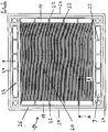
- Fig. 1 shows a first example of a device according to the invention in an exploded view, here designed as a heat exchanger.
- the device comprises a plurality of plate elements 1.1 - 1.3 (plate elements which have a profiling on at least one surface are also referred to below as flow plates) made of thermally conductive material, three of which are shown here.
- each of the three plate elements 1.1-1.3 has a one-sided profiling (the profiling itself is not shown in the figure), namely the profiling is in each case on the surface of the plate elements facing the viewer.
- This profiling forms flow channels for the fluids involved.
- the profiling is shown in detail in Fig. 2.
- flow spaces consisting of the individual flow channels of a profiled surface
- flow spaces between adjacent plate elements can alternate with be charged with a first and a second fluid.
- the first fluid flows between left 1.1 and middle 1.2 plate element, and between second 1.2 and right plate element 1.3 the second fluid. Beyond the right plate element 1.3, the first fluid etc. flows again.
- the feed and discharge channels for the two fluids are formed by openings 8, 9, 10, 11 that are aligned with one another at the edges of the plate elements 1.1 - 1.3.
- each of the four openings is provided with a plurality of webs 22 for mechanical stabilization.
- the two openings 10, 11 on the left and right edges are provided for the supply and discharge of the first fluid, and the two openings 8, 9 on the upper and lower edges for the supply and discharge of the second fluid.
- the flow channels from plate element to plate element are continuously rotated by 90 ° to one another.
- the two seals 5 are designed differently accordingly.
- the linear profile in the left 1.1 and right 1.3 plate elements runs parallel to the upper or lower edge and in the middle plate element 1.2 parallel to the left or right edge.
- the seals 5 used for realizing a reliable seal and for minimizing the production costs between two plate elements in each case are designed as circumferential seals which are integrated in a circumferential groove of a plate element surface.
- Prefabricated elastomer seals can be inserted into the sealing grooves.
- the use of elastomer seals enables their direct injection, so that a firm bond between the seal and the plate element arises. This considerably reduces the assembly effort.
- the supply and discharge channels are connected to external supply and discharge lines via flanges (not shown).
- the fluid In order to achieve the desired homogeneous flow distribution over the entire profiled area of the plate elements, the fluid must be routed through the outer supply and discharge lines with the lowest possible pressure loss and homogeneous flow distribution. This is achieved constructively through large flow cross sections in the area of the inlet and outlet channels of the flanges, in that the flanges have cutouts in the area of the inlet and outlet channels.
- a homogeneous flow guidance can be achieved by an intermediate plate which is arranged between the flange and the first plate element or the flange and the last plate element.
- a top view of a single, profiled plate element 1.4 as can be used in the flow module according to FIG. 1 but also in other versions of the device according to the invention (eg mass exchanger, reactor).
- the majority of the surface is occupied by the profiled area 20.
- the profiling forms rectilinear, parallel flow channels 30 (FIG. 4).
- the openings 8, 9, 10, 11 for the supply and discharge of the two fluids are arranged on the edges. Arranged in alignment one above the other, the openings 8, 9, 10, 11 form adjacent and superimposed flow plates of supply and discharge channels.
- the opening 10 for the supply of the first fluid is located on the right edge, the opening 11 for the removal of the first fluid is located on the opposite left edge.
- the first fluid flows through the flow channels shown in FIG Profiling.
- the openings extend along the edge of the plate element over the entire area of the profiling (transverse to the flow channels), so that a pronounced feed and discharge space for the fluid is formed.
- the opening 8 for the supply of the second fluid is located at the upper edge, and the opening for the removal of the second fluid is located on the opposite lower edge 9. This second fluid flows in the profile of the plate element adjacent to the plate element shown.
- the circumferential groove 26 seals supply and discharge channels to the outside and to the flow spaces between adjacent plate elements.
- the webs 22 according to the invention for mechanical stabilization are arranged in the openings for the feed and discharge spaces, since the fluid pressure in the feed and discharge channels tries to push the longitudinal strips 24 of the plate elements outwards.
- the webs are each arranged between the longitudinal strips 24 and the profiled area 20 of the plate element.
- the number of webs 22 and their width can be specifically adapted to the mechanical requirements.
- the surfaces of the webs which are arranged in the inlet area or outlet area of the profiling (here the webs in the openings 10 and 11) end somewhat below the profiled plate surface (approximately at the lower level of the profiling). This enables an improved supply of the flow channels in the web area in order to use the entire area for heat or material exchange.
- the structure of the webs 22 is shown in detail in FIG. 3.
- a variety of materials are possible for the flow plates. Plate designs made of metal, plastic or graphite have proven to be particularly advantageous with regard to performance data and production costs. These materials can be processed to produce the profiles and the grooves for the seals with simple and inexpensive manufacturing processes such as soft stamping / punching, injection molding, etc. Cutting processes are also possible.
- the profiled plate element 1.4 shown here has a rectangular base. This enables a homogeneous supply and discharge of the fluids through the openings without separate flow distributors. All flow channels on a plate surface are directly connected to the plate opening.
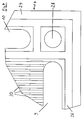
- FIG. 3 shows a sectional illustration of the plate element 1.4 according to FIG. 2 (section along the line AA in FIG. 2). It can be seen that the web 22 ends below the plate element surface 21, namely at the level of the bottom 31 of the channels 30. The surface 23 of the web 22 and the bottom 31 of the channels 30 thus merge seamlessly into one another.
- the reference numerals 24, 26, 11 denote the same components as in FIG. 2.
- FIG. 4 shows a detail of the plate element 1.4 according to FIG. 2.
- the flow channels 30 on the plate element surface can be seen, as well as the openings 10.9 for the supply of one fluid and the discharge of the other fluid.
- the circumferential groove 26 is provided for the integration of the circumferential seal.
- In the outer corner of the plate element there is a bore 28 for the tie rods with which the ones lying one above the other or next to one another Plate elements can be pressed together.
- Fig. 5 shows a further embodiment of the invention, which is designed as a heat exchanger.
- the two outer plate elements 1.6, 1.8 are now profiled on both surfaces, while the middle plate element 1.7 has a smooth surface on both sides and is designed as a dense film. Otherwise, this embodiment corresponds to that shown in FIG. 1.
- FIG. 6 shows an embodiment designed as a membrane module.
- Three plate elements 1.9-1.11 are shown, the two outer 1.9.1.11 being dense flow plates profiled on both sides.
- the middle plate element 1.10 is designed as a membrane, which enables a mass transfer of the two fluids adjacent to the membrane.
- a support plate 6 for supporting the adjacent seal 5 is arranged in each case in the inlet area and outlet area of the flow channels. This support plate 6 also prevents the membrane 1.10 from penetrating into the flow channels. In addition, a reliable seal is achieved by integrating the support plate.
- the three plate elements 1.12-1.14 shown are each profiled on one side, the profiling being present on the side facing the viewer.
- the profiled surfaces are coated with a catalyst, while the middle plate element 1.13 has no catalyst coating.
- the two outer plate elements 1.15, 1.17 are profiled on both sides, but have no catalyst coating.
- the middle plate element 1.16 is designed as a dense film, the side facing away from the viewer being coated with a catalyst. With this arrangement, only the fluid (reactant), which is located between the middle 1.16 and right 1.17 plate element and on this side of the left plate element 1.15, comes into contact with the catalyst, while the other fluid (heat transfer medium), which is between left 1.15 and middle 1.16 Plate module and located beyond the right plate element 1.17, has no contact with the catalyst.
Landscapes
- Chemical & Material Sciences (AREA)
- Engineering & Computer Science (AREA)
- Organic Chemistry (AREA)
- Chemical Kinetics & Catalysis (AREA)
- Physics & Mathematics (AREA)
- Thermal Sciences (AREA)
- Mechanical Engineering (AREA)
- General Engineering & Computer Science (AREA)
- Heat-Exchange Devices With Radiators And Conduit Assemblies (AREA)
- Cooling Or The Like Of Semiconductors Or Solid State Devices (AREA)
- Physical Or Chemical Processes And Apparatus (AREA)
Applications Claiming Priority (2)
| Application Number | Priority Date | Filing Date | Title |
|---|---|---|---|
| DE19617396 | 1996-05-02 | ||
| DE19617396A DE19617396C2 (de) | 1996-05-02 | 1996-05-02 | Strömungsmodul |
Publications (3)
| Publication Number | Publication Date |
|---|---|
| EP0805328A2 true EP0805328A2 (fr) | 1997-11-05 |
| EP0805328A3 EP0805328A3 (fr) | 1999-03-10 |
| EP0805328B1 EP0805328B1 (fr) | 2002-08-28 |
Family
ID=7792964
Family Applications (1)
| Application Number | Title | Priority Date | Filing Date |
|---|---|---|---|
| EP97105472A Expired - Lifetime EP0805328B1 (fr) | 1996-05-02 | 1997-04-02 | Module d'écoulement |
Country Status (3)
| Country | Link |
|---|---|
| US (1) | US5829517A (fr) |
| EP (1) | EP0805328B1 (fr) |
| DE (2) | DE19617396C2 (fr) |
Cited By (10)
| Publication number | Priority date | Publication date | Assignee | Title |
|---|---|---|---|---|
| WO2002050419A1 (fr) * | 2000-12-21 | 2002-06-27 | Dana Canada Corporation | Echangeur de chaleur a plaque a ailettes |
| DE10104602A1 (de) * | 2001-02-02 | 2002-07-18 | Xcellsis Gmbh | Wärmetauscher |
| WO2003054468A1 (fr) | 2001-12-10 | 2003-07-03 | Robert Bosch Gmbh | Dispositif de transmission de chaleur |
| US7011142B2 (en) | 2000-12-21 | 2006-03-14 | Dana Canada Corporation | Finned plate heat exchanger |
| US7025127B2 (en) | 2002-07-05 | 2006-04-11 | Dana Canada Corporation | Baffled surface cooled heat exchanger |
| US7182125B2 (en) | 2003-11-28 | 2007-02-27 | Dana Canada Corporation | Low profile heat exchanger with notched turbulizer |
| US7213638B2 (en) | 2003-04-11 | 2007-05-08 | Dana Canada Corporation | Heat exchanger with flow circuiting end caps |
| EP1477761A3 (fr) * | 2003-05-16 | 2007-07-25 | API Schmidt-Bretten GmbH & Co. KG | Echangeur de chaleur à plaques |
| WO2011003496A3 (fr) * | 2009-07-08 | 2011-03-03 | Sartorius Stedim Biotech Gmbh | Échangeur de chaleur à plaques |
| WO2019219131A2 (fr) | 2018-05-16 | 2019-11-21 | Solarspring Gmbh | Module de plaques pour la distillation par membrane |
Families Citing this family (34)
| Publication number | Priority date | Publication date | Assignee | Title |
|---|---|---|---|---|
| JP4063430B2 (ja) | 1998-12-15 | 2008-03-19 | 大阪瓦斯株式会社 | 流体処理装置 |
| DE19909881A1 (de) * | 1999-03-06 | 2000-09-07 | Behr Gmbh & Co | Wärmeübertrager in Kreuzstrom-Bauweise |
| EP1767886B1 (fr) * | 1999-03-27 | 2016-04-13 | CHART HEAT EXCHANGERS Limited Partnership | Dispositif de mélange des fluides |
| DE19944185A1 (de) * | 1999-09-15 | 2001-03-29 | Xcellsis Gmbh | Vorrichtung zur Durchführung einer heterogen katalysierten Reaktion und Verfahren zu deren Herstellung |
| DK1248675T3 (da) * | 2000-01-11 | 2005-09-19 | Accentus Plc | Katalytisk reaktor |
| DE10013437C1 (de) * | 2000-03-17 | 2001-12-06 | Xcellsis Gmbh | Folienpaket für einen aus Folien aufgebauten Verdampfer |
| US6893619B1 (en) * | 2000-09-13 | 2005-05-17 | Ford Global Technologies, Llc | Plate-frame heat exchange reactor with serial cross-flow geometry |
| FR2823995B1 (fr) * | 2001-04-25 | 2008-06-06 | Alfa Laval Vicarb | Dispositif perfectionne d'echange et/ou de reaction entre fluides |
| DE10134761C2 (de) * | 2001-07-12 | 2003-05-28 | Visteon Global Tech Inc | Wärmeübertrager, insbesondere zur thermischen Kopplung eines Glykol-Wasser-Kreislaufes und eines Hochdruckkältemittelkreislaufes |
| DE10153877A1 (de) * | 2001-11-02 | 2003-05-15 | Behr Gmbh & Co | Wärmeübertrager |
| CA2372399C (fr) * | 2002-02-19 | 2010-10-26 | Long Manufacturing Ltd. | Echangeur de chaleur a ailettes compactes |
| US6989134B2 (en) * | 2002-11-27 | 2006-01-24 | Velocys Inc. | Microchannel apparatus, methods of making microchannel apparatus, and processes of conducting unit operations |
| DE102004005832B4 (de) * | 2003-02-18 | 2005-12-08 | Dr. Schnabel Gmbh & Co Kg | Verbundwärmetauscher |
| US7015290B2 (en) * | 2003-02-24 | 2006-03-21 | Baker Hughes Incorporated | Method of preparing a polymer under predetermined temperature conditions, and apparatus therefor |
| GB2427373A (en) * | 2005-03-05 | 2006-12-27 | Catal Internat Ltd | A reactor |
| US20070235174A1 (en) * | 2005-12-23 | 2007-10-11 | Dakhoul Youssef M | Heat exchanger |
| US20070298486A1 (en) * | 2006-06-16 | 2007-12-27 | Velocys Inc. | Microchannel Apparatus and Methods Of Conducting Unit Operations With Disrupted Flow |
| US8033326B2 (en) * | 2006-12-20 | 2011-10-11 | Caterpillar Inc. | Heat exchanger |
| DE102006061863A1 (de) * | 2006-12-21 | 2008-06-26 | Henkel Kgaa | Haarkonditionierende Mittel mit ausgewählten kationischen Polymeren und wasserlöslichen Silikonen |
| DE102008048014A1 (de) | 2008-09-12 | 2010-04-15 | Esk Ceramics Gmbh & Co. Kg | Bauteil aus einem Stapel keramischer Platten |
| WO2010040819A1 (fr) * | 2008-10-10 | 2010-04-15 | Gambro Lundia Ab | Échangeur de chaleur et procédé d’échange de chaleur |
| DE102009020128A1 (de) * | 2009-05-06 | 2010-11-11 | Wolfgang Heinzl | Modulares Strömungssystem |
| DE102010041289B4 (de) * | 2009-09-23 | 2017-09-07 | L-Dcs Technology Gmbh | Stoff- und Wärmeaustauscherplatte sowie ein Stoff- und Wärmeaustauschreaktor mit einer solchen Stoff- und Wärmeaustauscherplatte |
| DE202009015586U1 (de) * | 2009-11-12 | 2011-03-24 | Autokühler GmbH & Co. KG | Wärmeaustauschernetz |
| DE102010048160A1 (de) | 2010-10-11 | 2012-04-12 | Aaa Water Technologies Ag | Mehrstufige Membrandestillationsvorrichtung |
| US8919746B2 (en) | 2011-01-13 | 2014-12-30 | Dana Canada Corporation | Humidifier for fuel cell systems |
| US9735438B2 (en) | 2011-01-13 | 2017-08-15 | Dana Canada Corporation | Humidifier for fuel cell systems |
| US9634340B2 (en) | 2012-10-17 | 2017-04-25 | GM Global Technology Operations LLC | Plate-style water vapor transfer unit with integral headers |
| US10046303B2 (en) | 2013-04-26 | 2018-08-14 | Corning Incorporated | Disassemblable stacked flow reactor |
| US11400417B2 (en) | 2018-06-08 | 2022-08-02 | Evcon Gmbh | Modular flow system with enhanced vapor and/or liquid channel configuration |
| US12134075B2 (en) | 2018-06-08 | 2024-11-05 | Evcon Gmbh | Membrane distillation apparatus for producing water |
| US11712662B2 (en) | 2018-06-08 | 2023-08-01 | Evcon Gmbh | Modular flow system with internal strut members |
| EP3801800B1 (fr) | 2018-06-08 | 2023-08-30 | EvCon GmbH | Appareil de distillation à membrane multiétages |
| WO2019233609A1 (fr) | 2018-06-08 | 2019-12-12 | Evcon Gmbh | Système d'écoulement modulaire avec passage de liquide asymétrique ou discontinu |
Family Cites Families (26)
| Publication number | Priority date | Publication date | Assignee | Title |
|---|---|---|---|---|
| US1056385A (en) * | 1911-12-18 | 1913-03-18 | Walter Francis Goodrich | Apparatus for heating and cooling liquids. |
| US1770254A (en) * | 1928-03-07 | 1930-07-08 | Seligman Richard | Heat-exchange apparatus |
| DE653877C (de) * | 1935-10-16 | 1937-12-04 | Otto Beneke | Plattenerhitzer fuer Milch und andere Fluessigkeiten |
| GB477999A (en) * | 1936-07-13 | 1938-01-11 | Edwin Prestage | Improvements in or relating to plate heat-exchange apparatus |
| US2160928A (en) * | 1937-07-28 | 1939-06-06 | Standard Oil Co | Split section heat exchanger |
| US2229306A (en) * | 1937-08-05 | 1941-01-21 | Prestage Edwin | Plate-type heat-exchange apparatus |
| DE725155C (de) * | 1939-04-14 | 1942-09-16 | Schmidt Kuehlerfabrik W | Plattenwaermeaustauscher |
| US2528013A (en) * | 1944-12-18 | 1950-10-31 | Lister & Co Ltd R A | Plate type heat exchanger |
| GB732637A (en) * | 1952-10-30 | 1955-06-29 | Machf Bolnes Voorheen J H Van | Improvements in or relating to plate heat exchangers |
| DE1501617A1 (de) * | 1964-04-03 | 1969-11-06 | Serck Radiators Ltd | Waermeaustauscher mit plattenfoermigen Elementen |
| DE2007033C3 (de) * | 1970-02-17 | 1979-06-21 | Hoechst Ag, 6000 Frankfurt | Plattenwärmetauscher aus Polytetrafluorethylen |
| US4124478A (en) * | 1977-02-07 | 1978-11-07 | Tsien Hsue C | Thin sheet apparatus and a fluid flow device |
| JPS5623700A (en) * | 1979-08-03 | 1981-03-06 | Fuji Heavy Ind Ltd | Heat exchanger |
| US4403652A (en) * | 1981-04-01 | 1983-09-13 | Crepaco, Inc. | Plate heat exchanger |
| FR2533021B1 (fr) * | 1982-09-15 | 1987-05-22 | Comp Generale Electricite | Echangeur de chaleur a plaques |
| DE3434415A1 (de) * | 1984-09-19 | 1986-03-27 | Siemens AG, 1000 Berlin und 8000 München | Brennwertheizgeraet, insbesondere fuer niedertemperaturheizungsanlagen |
| US4893673A (en) * | 1984-10-31 | 1990-01-16 | Rockwell International Corporation | Entry port inserts for internally manifolded stacked, finned-plate heat exchanger |
| DE3564340D1 (en) * | 1985-05-29 | 1988-09-15 | Sigri Gmbh | Procedure for manufacturing a plate heat exchanger |
| JPH01230991A (ja) * | 1988-03-09 | 1989-09-14 | Matsushita Seiko Co Ltd | 全熱交換器 |
| JPH07109773B2 (ja) * | 1989-02-28 | 1995-11-22 | 石川島播磨重工業株式会社 | 燃料電池を用いた発電装置 |
| JPH0831322B2 (ja) * | 1989-09-20 | 1996-03-27 | 株式会社日立製作所 | 内部改質型燃料電池およびそれを用いた発電プラント |
| JPH03177791A (ja) * | 1989-12-05 | 1991-08-01 | Matsushita Refrig Co Ltd | 積層型熱交換器 |
| JPH03177701A (ja) * | 1989-12-06 | 1991-08-01 | Sumitomo Metal Ind Ltd | 排熱回収方法 |
| DE4037969A1 (de) * | 1990-11-29 | 1992-06-04 | Schmidt Bretten W Gmbh | Plattenwaermeaustauscher |
| DE4223321A1 (de) * | 1992-07-16 | 1994-01-20 | Tenez A S | Geschweißter Plattenwärmetauscher |
| JP3427526B2 (ja) * | 1994-12-21 | 2003-07-22 | 株式会社デンソー | オイルクーラ |
-
1996
- 1996-05-02 DE DE19617396A patent/DE19617396C2/de not_active Expired - Fee Related
-
1997
- 1997-04-02 EP EP97105472A patent/EP0805328B1/fr not_active Expired - Lifetime
- 1997-04-02 DE DE59708032T patent/DE59708032D1/de not_active Expired - Fee Related
- 1997-05-02 US US08/850,931 patent/US5829517A/en not_active Expired - Fee Related
Cited By (12)
| Publication number | Priority date | Publication date | Assignee | Title |
|---|---|---|---|---|
| WO2002050419A1 (fr) * | 2000-12-21 | 2002-06-27 | Dana Canada Corporation | Echangeur de chaleur a plaque a ailettes |
| US7011142B2 (en) | 2000-12-21 | 2006-03-14 | Dana Canada Corporation | Finned plate heat exchanger |
| CZ299165B6 (cs) * | 2000-12-21 | 2008-05-07 | Dana Canada Corporation | Výmeník tepla a zpusob výroby výmeníku tepla |
| DE10104602A1 (de) * | 2001-02-02 | 2002-07-18 | Xcellsis Gmbh | Wärmetauscher |
| WO2003054468A1 (fr) | 2001-12-10 | 2003-07-03 | Robert Bosch Gmbh | Dispositif de transmission de chaleur |
| US7025127B2 (en) | 2002-07-05 | 2006-04-11 | Dana Canada Corporation | Baffled surface cooled heat exchanger |
| US7213638B2 (en) | 2003-04-11 | 2007-05-08 | Dana Canada Corporation | Heat exchanger with flow circuiting end caps |
| EP1477761A3 (fr) * | 2003-05-16 | 2007-07-25 | API Schmidt-Bretten GmbH & Co. KG | Echangeur de chaleur à plaques |
| US7182125B2 (en) | 2003-11-28 | 2007-02-27 | Dana Canada Corporation | Low profile heat exchanger with notched turbulizer |
| WO2011003496A3 (fr) * | 2009-07-08 | 2011-03-03 | Sartorius Stedim Biotech Gmbh | Échangeur de chaleur à plaques |
| US9228784B2 (en) | 2009-07-08 | 2016-01-05 | Sartorius Stedim Biotech Gmbh | Plate heat exchanger |
| WO2019219131A2 (fr) | 2018-05-16 | 2019-11-21 | Solarspring Gmbh | Module de plaques pour la distillation par membrane |
Also Published As
| Publication number | Publication date |
|---|---|
| DE19617396C2 (de) | 1998-03-26 |
| EP0805328B1 (fr) | 2002-08-28 |
| DE59708032D1 (de) | 2002-10-02 |
| DE19617396A1 (de) | 1997-11-06 |
| EP0805328A3 (fr) | 1999-03-10 |
| US5829517A (en) | 1998-11-03 |
Similar Documents
| Publication | Publication Date | Title |
|---|---|---|
| EP0805328B1 (fr) | Module d'écoulement | |
| EP0694729B1 (fr) | Module de vaporisation | |
| DE19528117B4 (de) | Wärmeübertrager mit Plattenstapelaufbau | |
| EP1013331A1 (fr) | Module à membranes empilées pour la séparation sélective de gaz | |
| EP0978874A2 (fr) | Refroidisseur | |
| DE102008033210A1 (de) | Bipolarplatte für eine Brennstoffzellenanordnung, insbesondere zur Anordnung zwischen zwei benachbarten Membran-Elektroden-Anordnungen | |
| EP1506054A1 (fr) | Microreacteur et micro-echangeur thermique | |
| EP1585589B1 (fr) | Module a membranes pour la separation de l'hydrogene et procede de fabrication dudit module | |
| DE102006009844A1 (de) | Bipolarplatte, insbesondere für einen Brennstoffzellenstapel eines Fahrzeugs | |
| WO2019020284A1 (fr) | Structure distributrice pour la fourniture d'au moins un gaz réactif | |
| DE102008033209A1 (de) | Brennstoffzellenanordnung | |
| DE10226388A1 (de) | Separator für Brennstoffzelle | |
| DE1809545A1 (de) | Plattenwaermetauscher | |
| DE102024124856A1 (de) | Bipolarplatte für ein elektrochemisches system | |
| EP1920208A1 (fr) | Dispositif echangeur de chaleur pour chauffer ou refroidir rapidement des fluides | |
| DE102006056468A1 (de) | Bipolarplatte, insbesondere für einen Brennstoffzellenstapel eines Fahrzeugs | |
| DE102020208942A1 (de) | Brennstoffzellenstapel mit unterbrochenen Bipolarplatten | |
| DE19853750A1 (de) | Kühler zur Verwendung als Wärmesenke für elektrische oder elektronische Komponenten | |
| EP0423857B1 (fr) | Procédé pour la production d'une tôle en U avec des tôles disposées parallèlement l'une à l'autre, dispositif pour la mise en oeuvre du procédé | |
| DE102005035247B4 (de) | Fluidverteiler mit binärer Struktur | |
| EP1511102A2 (fr) | Plaque bipolaire et empilement de piles à combustible | |
| DE102022118939A1 (de) | Plattenstapel für eine Befeuchtungseinrichtung und Befeuchtungseinrichtung | |
| DE102022208625A1 (de) | Separatorplatte und elektrochemische Zelle | |
| DE2245849A1 (de) | Waermeaustauscher | |
| DE3509895C2 (fr) |
Legal Events
| Date | Code | Title | Description |
|---|---|---|---|
| PUAI | Public reference made under article 153(3) epc to a published international application that has entered the european phase |
Free format text: ORIGINAL CODE: 0009012 |
|
| AK | Designated contracting states |
Kind code of ref document: A2 Designated state(s): DE FR GB IT |
|
| RAP1 | Party data changed (applicant data changed or rights of an application transferred) |
Owner name: DAIMLER-BENZ AKTIENGESELLSCHAFT |
|
| RAP1 | Party data changed (applicant data changed or rights of an application transferred) |
Owner name: BALLARD POWER SYSTEMS INC. |
|
| PUAL | Search report despatched |
Free format text: ORIGINAL CODE: 0009013 |
|
| AK | Designated contracting states |
Kind code of ref document: A3 Designated state(s): DE FR GB IT |
|
| 17P | Request for examination filed |
Effective date: 19990414 |
|
| 17Q | First examination report despatched |
Effective date: 20010426 |
|
| GRAG | Despatch of communication of intention to grant |
Free format text: ORIGINAL CODE: EPIDOS AGRA |
|
| GRAG | Despatch of communication of intention to grant |
Free format text: ORIGINAL CODE: EPIDOS AGRA |
|
| GRAH | Despatch of communication of intention to grant a patent |
Free format text: ORIGINAL CODE: EPIDOS IGRA |
|
| GRAH | Despatch of communication of intention to grant a patent |
Free format text: ORIGINAL CODE: EPIDOS IGRA |
|
| GRAA | (expected) grant |
Free format text: ORIGINAL CODE: 0009210 |
|
| AK | Designated contracting states |
Kind code of ref document: B1 Designated state(s): DE FR GB IT |
|
| PG25 | Lapsed in a contracting state [announced via postgrant information from national office to epo] |
Ref country code: IT Free format text: LAPSE BECAUSE OF FAILURE TO SUBMIT A TRANSLATION OF THE DESCRIPTION OR TO PAY THE FEE WITHIN THE PRESCRIBED TIME-LIMIT;WARNING: LAPSES OF ITALIAN PATENTS WITH EFFECTIVE DATE BEFORE 2007 MAY HAVE OCCURRED AT ANY TIME BEFORE 2007. THE CORRECT EFFECTIVE DATE MAY BE DIFFERENT FROM THE ONE RECORDED. Effective date: 20020828 Ref country code: FR Free format text: LAPSE BECAUSE OF NON-PAYMENT OF DUE FEES Effective date: 20020828 |
|
| REG | Reference to a national code |
Ref country code: GB Ref legal event code: FG4D Free format text: NOT ENGLISH |
|
| REF | Corresponds to: |
Ref document number: 59708032 Country of ref document: DE Date of ref document: 20021002 |
|
| GBT | Gb: translation of ep patent filed (gb section 77(6)(a)/1977) |
Effective date: 20030122 |
|
| EN | Fr: translation not filed | ||
| PLBE | No opposition filed within time limit |
Free format text: ORIGINAL CODE: 0009261 |
|
| STAA | Information on the status of an ep patent application or granted ep patent |
Free format text: STATUS: NO OPPOSITION FILED WITHIN TIME LIMIT |
|
| 26N | No opposition filed |
Effective date: 20030530 |
|
| PG25 | Lapsed in a contracting state [announced via postgrant information from national office to epo] |
Ref country code: DE Free format text: LAPSE BECAUSE OF NON-PAYMENT OF DUE FEES Effective date: 20031101 |
|
| GBPC | Gb: european patent ceased through non-payment of renewal fee |
Effective date: 20070402 |
|
| PG25 | Lapsed in a contracting state [announced via postgrant information from national office to epo] |
Ref country code: GB Free format text: LAPSE BECAUSE OF NON-PAYMENT OF DUE FEES Effective date: 20070402 |
|
| PGFP | Annual fee paid to national office [announced via postgrant information from national office to epo] |
Ref country code: GB Payment date: 20060329 Year of fee payment: 10 |