EP0805300A2 - Dispositif de commande pour une installation d'aspiration - Google Patents
Dispositif de commande pour une installation d'aspiration Download PDFInfo
- Publication number
- EP0805300A2 EP0805300A2 EP97106766A EP97106766A EP0805300A2 EP 0805300 A2 EP0805300 A2 EP 0805300A2 EP 97106766 A EP97106766 A EP 97106766A EP 97106766 A EP97106766 A EP 97106766A EP 0805300 A2 EP0805300 A2 EP 0805300A2
- Authority
- EP
- European Patent Office
- Prior art keywords
- chamber
- flap
- control device
- pressure
- cylinder
- Prior art date
- Legal status (The legal status is an assumption and is not a legal conclusion. Google has not performed a legal analysis and makes no representation as to the accuracy of the status listed.)
- Withdrawn
Links
Images


Classifications
-
- F—MECHANICAL ENGINEERING; LIGHTING; HEATING; WEAPONS; BLASTING
- F16—ENGINEERING ELEMENTS AND UNITS; GENERAL MEASURES FOR PRODUCING AND MAINTAINING EFFECTIVE FUNCTIONING OF MACHINES OR INSTALLATIONS; THERMAL INSULATION IN GENERAL
- F16L—PIPES; JOINTS OR FITTINGS FOR PIPES; SUPPORTS FOR PIPES, CABLES OR PROTECTIVE TUBING; MEANS FOR THERMAL INSULATION IN GENERAL
- F16L55/00—Devices or appurtenances for use in, or in connection with, pipes or pipe systems
- F16L55/10—Means for stopping flow from or in pipes or hoses
- F16L55/1018—Pivoting closing devices
Definitions
- the invention relates to a control device of a suction system for the simultaneous suction of several machines or the like, in which a shut-off device automatically releases the cross section of the respective suction line when a machine is switched on and shuts off when switched off, with a chamber arranged in the suction line in which the shut-off device in Form of a flap is pivotally mounted about an axis on the chamber side in the open and closed position for the exhaust air cross section and is connected to a pneumatic lifting element counteracting a return force for the opening movement.
- This control device has the great advantage over the conventional control devices, which usually work with a slide as a shut-off device, that when individual machines are switched off, the cross section of the associated suction line is not completely sealed, but rather that the flap is created by the vacuum in the line caused by the suction fan counter to the spring force up to a certain position in which the spring force is in equilibrium with the aerodynamic force stands, is pulled up and thus a certain proportion of additional air is automatically drawn into the suction system through the suction lines of the switched off machine. So there is always a sufficiently large volume of transport air and thus a sufficiently high flow rate in the suction line system, even with only one switched on machine, so that deposits, for. B. of dust and chips, which can otherwise lead to complete blockage of the suction system can be safely avoided.
- the pneumatic member is a double-acting cylinder with cylinder chambers arranged on both sides of a piston, one side of the piston being acted upon by a predetermined pressure (opening pressure) in the open position of the flap and the other side of the piston by an adjustable pressure which counteracts the opening pressure (Control pressure) is applied.
- the return force can be varied at the same time without the return element, for. B. the return spring itself must be adjusted.
- control pressure in the lifting elements of a plurality of flaps can be adjusted via a pressure reducer connected to a compressed air line.
- the entire system can be set using only a single adjustable pressure reducer so that there is an optimal air speed in the suction line in every switching state of the machines.
- the adjustable pressure reducer is advantageously located in an easily accessible location, e.g. B. in the area in which the flow velocity in the suction line is measured.
- the flap can be connected to at least one return spring acting parallel to the lifting element in the closed position.
- This return spring is advantageously provided with at least one actuator for adjusting the return force.
- the setting only serves to compensate for the different damper areas under negative pressure with different suction cross-sections or when using different cylinders as lifting elements. This setting only has to be done once before the entire control device is installed and can already be carried out in the factory.
- each flap is controlled separately with its own pressure reducer, which is located in an easily accessible area, e.g. B. located on the machine.
- the relative presetting of the individual return springs can be dispensed with.
- the entire transport air volume in the extraction system can thus be set, controlled and / or changed in a significantly simpler, faster and more precise manner by the present invention.
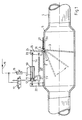
- the control device has a chamber (5) which is arranged in the suction line (4) of the respective machine (2) and has an at least partially angular cross section.
- this chamber (5) there is the shut-off device (3) in the form of a flap (3) which moves around an axis (6) located on a flat wall (7) of the chamber (5) into the opening and closing position for the exhaust air cross section is pivotally mounted.
- the chamber wall (7) there is a slot (8) on the swivel axis (6) through which the flap (3) is guided outwards beyond the swivel axis (6) with an extended flap part (24) and there with the lifting element (10) and a return spring (20) is coupled.
- the flap (3) is cranked outside the chamber (5) on the swivel axis (6), so that in the open position of the flap (3) the rear surface (25) of the outer flap part (24) as seen from the swivel axis (6) outside of the part (7H) of the chamber wall (7) located behind the slot (8) and the flap (3) at the cranking point (28) is guided through the slot (8) into the chamber (5) and under the pivot axis (6) runs almost parallel to the part (7V) of the chamber wall (7) lying in front of the pivot axis (6).
- a tab (23) is located on the front surface of the outer flap part (24) as seen from the swivel axis (6).
- the piston rod (14) of the double-acting cylinder (10) and the return spring (20) are pivotably (articulated) attached to this tab (23).
- the other end of the return spring (20) is pivotally (articulated) attached via an actuator (21) with a second tab (22) attached to the outside of the chamber (5).
- the other side of the cylinders (10) is also pivotably articulated on this tab (22).
- the spring tension of the return spring (20) can be set via the actuator (21). With this setting option, the return force can be set as a function of the cross-sectional area of the flap (3) and the size of the cylinder (10) relative to the other control devices (1) in the suction system (30).
- the cylinder (10) is a double-acting cylinder (10) with cylinder chambers (12, 13) arranged on both sides of a piston (11).
- One cylinder chamber (12) of the cylinder (10) is connected as a main chamber (12) with a 3/2-way valve (17), which, for. B. with the power switch of the respective machine (2) is coupled in terms of control.
- the cylinder chamber (12) is connected to a compressed air line (19) with a predetermined pressure via this valve (17).
- the pressure in this line (19) is approximately 5 to 6 bar.
- the corresponding piston side (15) is thereby subjected to the predetermined pressure and the piston (11) is pushed out of the cylinder (10), whereby the flap (3) is brought into the open position.
- the main chamber (12) When the machine (2) is switched off, the main chamber (12) is automatically vented through the valve (17). The flap (3) is then pulled into the closed position by the return spring (20).
- the valve (17) is a 3/2-way solenoid valve, which is switched so that the main chamber (12) is vented when de-energized and the flap (3) is closed by the return spring (20).
- the respective suction line (4) In the event of a power failure, e.g. B. due to a fire or in the event of an emergency shutdown of the entire suction system (30), the respective suction line (4) is therefore automatically closed.
- the other cylinder chamber (13) is connected as a control chamber (13) to the compressed air line (19) via an adjustable pressure reducer (18).
- a pressure of approximately 2 to 3 bar is normally introduced into the control chamber (13) via this adjustable pressure reducer (18).
- This pressure in the control chamber (13) acts in parallel with the return force of the return spring (20).
- the actuator (21) Since the permanently set control pressure acts constantly on the cylinder (10), it also supports the safe delivery of the automatic valve.
- machines (2) are each connected via separate suction lines (4) and separate control devices (1) to a main suction line (31), on the end of which there is a suction fan (32) (see FIG. 3).
- the control chambers (13) of the cylinders (10) of a plurality of flaps (3) or control devices (1) are advantageously connected to the compressed air line (19) via a common pressure reducer (18) (see FIG. 2).
- additional machines (2) to the suction system (30), which are connected to the main line (31) via a simple OPEN-CLOSE control device (1A) and through which no additional air is generated when the machines (2) are switched off can be pulled.
- an additional vent opening is not necessary. It is sufficient if the additional air is drawn exclusively from the machine connection. This reduces manufacturing costs. In addition, the air intake noise that inevitably occurs at the ventilation openings is eliminated. Of course, it is also possible, if desired, to install additional ventilation openings.
- a relatively inexpensive solution is to widen the slot (8) in the chamber wall (7) as an air inlet. Since the outside flap part (24) automatically lies over the slot (8) when the flap (3) is opened, the flow cross section through the widened slot (8) is then automatically reduced the further the flap (3) is opened. When the flap (3) is fully opened, ie when the machine (2) is switched on, the auxiliary air opening formed by the widened slot (8) is completely closed by the outer flap part (24).
- a single-acting pressure medium cylinder (10A) with an associated, single-acting solenoid valve (MV) is connected to the outer flap part (24) of the flap (3).
- the outer flap part (24) of the flap (3) is also assigned a compression spring (DF) which, with a length end, rests on a spherical bearing, such as a crest (35) or tip and a spring plate (36) which is movable thereon, the chamber (5). namely that it is pivotally supported on the wall part (7V) and rests with the other length end on an abutment (37) attached to the flap part (24) in the form of an angle.
- DF compression spring
- the articulation point (38) of the push rod (14) of the pressure medium cylinder (10A) and the counter bearing (37) of the pressure spring (DF) are laterally offset from one another on the outer flap part (24).
- the so-called opening pressure via the 3/2-way solenoid valve (17) takes effect when the machine is switched on, as a result of which the flap (3) is brought into the safe opening position against the set control pressure.
- the set control pressure is switched off via a single-acting solenoid valve (MV), so that the air flow in the tube (5) swings the flap (3) into the open position, the flap part (24) standing outwards through the assigned opening (8) is sucked into the housing (5) and holds the flap (3) securely in the end position.
- MV single-acting solenoid valve
- the one on the outside can also be used standing flap part simple compression spring (DF) can be attached.
- the solenoid valve (MV) opens again and the flap (3) swivels back in accordance with the set control pressure.
- the advantage of this version is that only a single-acting cylinder (10A) and a single-acting solenoid valve (MV) are required. In addition, only one pneumatic line needs to be installed for each damper when installing the pneumatics.
- the solenoid valve (MV) counteracts the negative pressure (UD) in an adjustable manner, which guarantees an adjustable amount of the necessary transport air in every operating situation.
- the control pressure is set individually for each flap (3) and jointly for several flaps (3).
Landscapes
- Engineering & Computer Science (AREA)
- General Engineering & Computer Science (AREA)
- Mechanical Engineering (AREA)
- Paper (AREA)
- Fluid-Pressure Circuits (AREA)
- Control And Other Processes For Unpacking Of Materials (AREA)
Applications Claiming Priority (2)
| Application Number | Priority Date | Filing Date | Title |
|---|---|---|---|
| DE19617302 | 1996-04-30 | ||
| DE1996117302 DE19617302C1 (de) | 1996-04-30 | 1996-04-30 | Steuervorrichtung in einer Absauganlage |
Publications (2)
| Publication Number | Publication Date |
|---|---|
| EP0805300A2 true EP0805300A2 (fr) | 1997-11-05 |
| EP0805300A3 EP0805300A3 (fr) | 1999-08-04 |
Family
ID=7792904
Family Applications (1)
| Application Number | Title | Priority Date | Filing Date |
|---|---|---|---|
| EP97106766A Withdrawn EP0805300A3 (fr) | 1996-04-30 | 1997-04-24 | Dispositif de commande pour une installation d'aspiration |
Country Status (2)
| Country | Link |
|---|---|
| EP (1) | EP0805300A3 (fr) |
| DE (1) | DE19617302C1 (fr) |
Cited By (6)
| Publication number | Priority date | Publication date | Assignee | Title |
|---|---|---|---|---|
| DE102004024525A1 (de) * | 2004-05-18 | 2005-12-22 | Franz Schuck Gmbh | Vorrichtung zum Absperren einer Rohrleitung für ein fließfähiges Medium |
| WO2006059941A1 (fr) * | 2004-11-30 | 2006-06-08 | Jan Norrman | Dispositif d'arret pour tuyau |
| DE102008005925B4 (de) * | 2008-01-24 | 2012-10-04 | Sebastian Haas | Rückschlagklappe mit Hilfsklappe |
| EP2530396A1 (fr) * | 2011-06-01 | 2012-12-05 | Koolair, S.A. | Valve de régulation de débit d'air |
| FR3012357A1 (fr) * | 2013-10-25 | 2015-05-01 | Innotronic | Dispositif de mise en obturation amovible et adaptable pour une targette d'obturation d'aspiration d'une machine de travail industriel et machine equipee d'un tel dispositif |
| CN107883060A (zh) * | 2017-11-20 | 2018-04-06 | 中船重工(沈阳)辽海输油设备有限公司 | 一种钢制管道弧板捞取装置 |
Families Citing this family (2)
| Publication number | Priority date | Publication date | Assignee | Title |
|---|---|---|---|---|
| DE102004010480A1 (de) * | 2004-03-04 | 2005-09-22 | Goss International Montataire S.A. | Vorrichtung und Verfahren zur Absaugung von Spänen in einer bedruckstoffverarbeitenden Maschine |
| DE102009054693A1 (de) * | 2009-12-15 | 2011-06-16 | Alfred Kärcher Gmbh & Co. Kg | Sauggerät sowie Absauganlage |
Citations (4)
| Publication number | Priority date | Publication date | Assignee | Title |
|---|---|---|---|---|
| FR1313310A (fr) * | 1961-11-17 | 1962-12-28 | Nouveaux Ateliers Lebrun Sa | Installation de climatisation |
| US4042173A (en) * | 1975-09-04 | 1977-08-16 | Barber-Colman Company | Method and apparatus for controlling volume air flow |
| GB1533137A (en) * | 1975-09-26 | 1978-11-22 | Trox Gmbh Geb | Controlling the rate of gas flow through a conduit |
| DE3722815A1 (de) * | 1987-04-04 | 1989-01-19 | Gerhard Peters | Steuervorrichtung in einer geblaeseabhaengigen absaugleitung |
Family Cites Families (1)
| Publication number | Priority date | Publication date | Assignee | Title |
|---|---|---|---|---|
| DE4241075C2 (de) * | 1992-12-05 | 1995-05-24 | Gerhard Peters | Steuervorrichtung in einer gebläseabhängigen Absaugleitung |
-
1996
- 1996-04-30 DE DE1996117302 patent/DE19617302C1/de not_active Expired - Fee Related
-
1997
- 1997-04-24 EP EP97106766A patent/EP0805300A3/fr not_active Withdrawn
Patent Citations (4)
| Publication number | Priority date | Publication date | Assignee | Title |
|---|---|---|---|---|
| FR1313310A (fr) * | 1961-11-17 | 1962-12-28 | Nouveaux Ateliers Lebrun Sa | Installation de climatisation |
| US4042173A (en) * | 1975-09-04 | 1977-08-16 | Barber-Colman Company | Method and apparatus for controlling volume air flow |
| GB1533137A (en) * | 1975-09-26 | 1978-11-22 | Trox Gmbh Geb | Controlling the rate of gas flow through a conduit |
| DE3722815A1 (de) * | 1987-04-04 | 1989-01-19 | Gerhard Peters | Steuervorrichtung in einer geblaeseabhaengigen absaugleitung |
Cited By (9)
| Publication number | Priority date | Publication date | Assignee | Title |
|---|---|---|---|---|
| DE102004024525A1 (de) * | 2004-05-18 | 2005-12-22 | Franz Schuck Gmbh | Vorrichtung zum Absperren einer Rohrleitung für ein fließfähiges Medium |
| DE102004024525B4 (de) * | 2004-05-18 | 2006-05-11 | Franz Schuck Gmbh | Stromwächter zum Absperren einer Rohrleitung für ein fließfähiges Medium |
| WO2006059941A1 (fr) * | 2004-11-30 | 2006-06-08 | Jan Norrman | Dispositif d'arret pour tuyau |
| DE102008005925B4 (de) * | 2008-01-24 | 2012-10-04 | Sebastian Haas | Rückschlagklappe mit Hilfsklappe |
| EP2530396A1 (fr) * | 2011-06-01 | 2012-12-05 | Koolair, S.A. | Valve de régulation de débit d'air |
| FR3012357A1 (fr) * | 2013-10-25 | 2015-05-01 | Innotronic | Dispositif de mise en obturation amovible et adaptable pour une targette d'obturation d'aspiration d'une machine de travail industriel et machine equipee d'un tel dispositif |
| WO2015059373A3 (fr) * | 2013-10-25 | 2015-06-18 | INNOTRONIC Société par actions simplifiées (SAS) | Dispositif de mise en obturation amovible et adaptable pour une targette d'obturation d'aspiration d'une machine de travail industriel et machine équipée d'un tel dispositif |
| CN107883060A (zh) * | 2017-11-20 | 2018-04-06 | 中船重工(沈阳)辽海输油设备有限公司 | 一种钢制管道弧板捞取装置 |
| CN107883060B (zh) * | 2017-11-20 | 2024-05-03 | 中船重工(沈阳)辽海输油设备有限公司 | 一种钢制管道弧板捞取装置 |
Also Published As
| Publication number | Publication date |
|---|---|
| EP0805300A3 (fr) | 1999-08-04 |
| DE19617302C1 (de) | 1997-12-04 |
Similar Documents
| Publication | Publication Date | Title |
|---|---|---|
| EP0282758B1 (fr) | Agencement de soupape | |
| DE102005053590B4 (de) | Rauchschutzanlage sowie Verfahren zum Abführen von Rauch aus Brandräumen eines Gebäudes und zur Rauchfreihaltung von Fluchtwegen des Gebäudes | |
| DD141562A5 (de) | Luftauslass | |
| EP0805300A2 (fr) | Dispositif de commande pour une installation d'aspiration | |
| DE3446810C1 (de) | Niveauregelventil mit Hoehenbegrenzung | |
| DE2519408A1 (de) | Luftmengenregler | |
| DE2643381C2 (de) | Dosierventil | |
| DE2542160A1 (de) | Volumenstromregler fuer lufttechnische anlagen | |
| EP0289712A2 (fr) | Régulateur de pression | |
| DE3408507A1 (de) | Anlage mit mehreren gasabzugsschraenken | |
| EP1519120B1 (fr) | Clapet coupe-feu à actionnement éléctrique | |
| CH641324A5 (de) | Vorrichtung zur regelung des unterdruckes in einem unterdruckleitungssystem, insbesondere fuer melkanlagen. | |
| DE2921561A1 (de) | Beatmungsventil | |
| DE2820115A1 (de) | Verfahren und anlage zur beeinflussung der raumlufttemperatur | |
| DE29519838U1 (de) | Stellantrieb für eine Auf-Zu-Regulierung eines Ventils | |
| DE69020320T2 (de) | Verfahren und Vorrichtung zur Änderung der Einstellung von Durchflussreglern. | |
| DE2730443A1 (de) | Belueftungseinrichtung fuer den innenraum eines kraftfahrzeugs | |
| DE1751159A1 (de) | Pneumatische Lineareinheit | |
| EP2908055B1 (fr) | Vanne de gaz dotée d'un système de contrôle d'air comprimé intégré | |
| DE69408746T2 (de) | Steuereinrichtung für einen Hydraulikmotor | |
| DE3521646A1 (de) | Druckabhaengig gesteuerter schalter | |
| DE2539825C3 (de) | Löschvorrichtung mit einem Strahlrohr zur Abgabe eines Pulverstrahls | |
| DE2917725A1 (de) | Individual-klimasystem mit verfahren und vorrichtung zum konstanthalten der eingestellten luftzufuhr ueber den einzelnen arbeitsplaetzen in arbeitsraeumen | |
| DE2750199C2 (de) | Entlastungsventil für von einem Drehstrom-Elektromotor angetriebenes Drehkolbengebläse | |
| DE202005001417U1 (de) | Hydraulische Steuervorrichtung |
Legal Events
| Date | Code | Title | Description |
|---|---|---|---|
| PUAI | Public reference made under article 153(3) epc to a published international application that has entered the european phase |
Free format text: ORIGINAL CODE: 0009012 |
|
| AK | Designated contracting states |
Kind code of ref document: A2 Designated state(s): AT BE CH DE DK ES FI FR GB IE IT LI NL SE |
|
| PUAL | Search report despatched |
Free format text: ORIGINAL CODE: 0009013 |
|
| AK | Designated contracting states |
Kind code of ref document: A3 Designated state(s): AT BE CH DE DK ES FR GB IE IT LI NL SE |
|
| RIC1 | Information provided on ipc code assigned before grant |
Free format text: 6F 16L 55/10 A, 6F 24F 11/04 B, 6F 24F 13/14 B, 6B 08B 15/00 B, 6B 24B 55/06 B |
|
| 17P | Request for examination filed |
Effective date: 20000201 |
|
| RBV | Designated contracting states (corrected) |
Designated state(s): AT BE CH DE DK ES FI FR GB IE IT LI NL SE |
|
| 17Q | First examination report despatched |
Effective date: 20030612 |
|
| GRAJ | Information related to disapproval of communication of intention to grant by the applicant or resumption of examination proceedings by the epo deleted |
Free format text: ORIGINAL CODE: EPIDOSDIGR1 |
|
| GRAP | Despatch of communication of intention to grant a patent |
Free format text: ORIGINAL CODE: EPIDOSNIGR1 |
|
| GRAP | Despatch of communication of intention to grant a patent |
Free format text: ORIGINAL CODE: EPIDOSNIGR1 |
|
| STAA | Information on the status of an ep patent application or granted ep patent |
Free format text: STATUS: THE APPLICATION IS DEEMED TO BE WITHDRAWN |
|
| 18D | Application deemed to be withdrawn |
Effective date: 20040721 |