EP0805300A2 - Control system for a suction equipment - Google Patents
Control system for a suction equipment Download PDFInfo
- Publication number
- EP0805300A2 EP0805300A2 EP97106766A EP97106766A EP0805300A2 EP 0805300 A2 EP0805300 A2 EP 0805300A2 EP 97106766 A EP97106766 A EP 97106766A EP 97106766 A EP97106766 A EP 97106766A EP 0805300 A2 EP0805300 A2 EP 0805300A2
- Authority
- EP
- European Patent Office
- Prior art keywords
- chamber
- flap
- control device
- pressure
- cylinder
- Prior art date
- Legal status (The legal status is an assumption and is not a legal conclusion. Google has not performed a legal analysis and makes no representation as to the accuracy of the status listed.)
- Withdrawn
Links
Images


Classifications
-
- F—MECHANICAL ENGINEERING; LIGHTING; HEATING; WEAPONS; BLASTING
- F16—ENGINEERING ELEMENTS AND UNITS; GENERAL MEASURES FOR PRODUCING AND MAINTAINING EFFECTIVE FUNCTIONING OF MACHINES OR INSTALLATIONS; THERMAL INSULATION IN GENERAL
- F16L—PIPES; JOINTS OR FITTINGS FOR PIPES; SUPPORTS FOR PIPES, CABLES OR PROTECTIVE TUBING; MEANS FOR THERMAL INSULATION IN GENERAL
- F16L55/00—Devices or appurtenances for use in, or in connection with, pipes or pipe systems
- F16L55/10—Means for stopping flow from or in pipes or hoses
- F16L55/1018—Pivoting closing devices
Definitions
- the invention relates to a control device of a suction system for the simultaneous suction of several machines or the like, in which a shut-off device automatically releases the cross section of the respective suction line when a machine is switched on and shuts off when switched off, with a chamber arranged in the suction line in which the shut-off device in Form of a flap is pivotally mounted about an axis on the chamber side in the open and closed position for the exhaust air cross section and is connected to a pneumatic lifting element counteracting a return force for the opening movement.
- This control device has the great advantage over the conventional control devices, which usually work with a slide as a shut-off device, that when individual machines are switched off, the cross section of the associated suction line is not completely sealed, but rather that the flap is created by the vacuum in the line caused by the suction fan counter to the spring force up to a certain position in which the spring force is in equilibrium with the aerodynamic force stands, is pulled up and thus a certain proportion of additional air is automatically drawn into the suction system through the suction lines of the switched off machine. So there is always a sufficiently large volume of transport air and thus a sufficiently high flow rate in the suction line system, even with only one switched on machine, so that deposits, for. B. of dust and chips, which can otherwise lead to complete blockage of the suction system can be safely avoided.
- the pneumatic member is a double-acting cylinder with cylinder chambers arranged on both sides of a piston, one side of the piston being acted upon by a predetermined pressure (opening pressure) in the open position of the flap and the other side of the piston by an adjustable pressure which counteracts the opening pressure (Control pressure) is applied.
- the return force can be varied at the same time without the return element, for. B. the return spring itself must be adjusted.
- control pressure in the lifting elements of a plurality of flaps can be adjusted via a pressure reducer connected to a compressed air line.
- the entire system can be set using only a single adjustable pressure reducer so that there is an optimal air speed in the suction line in every switching state of the machines.
- the adjustable pressure reducer is advantageously located in an easily accessible location, e.g. B. in the area in which the flow velocity in the suction line is measured.
- the flap can be connected to at least one return spring acting parallel to the lifting element in the closed position.
- This return spring is advantageously provided with at least one actuator for adjusting the return force.
- the setting only serves to compensate for the different damper areas under negative pressure with different suction cross-sections or when using different cylinders as lifting elements. This setting only has to be done once before the entire control device is installed and can already be carried out in the factory.
- each flap is controlled separately with its own pressure reducer, which is located in an easily accessible area, e.g. B. located on the machine.
- the relative presetting of the individual return springs can be dispensed with.
- the entire transport air volume in the extraction system can thus be set, controlled and / or changed in a significantly simpler, faster and more precise manner by the present invention.
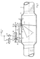
- the control device has a chamber (5) which is arranged in the suction line (4) of the respective machine (2) and has an at least partially angular cross section.
- this chamber (5) there is the shut-off device (3) in the form of a flap (3) which moves around an axis (6) located on a flat wall (7) of the chamber (5) into the opening and closing position for the exhaust air cross section is pivotally mounted.
- the chamber wall (7) there is a slot (8) on the swivel axis (6) through which the flap (3) is guided outwards beyond the swivel axis (6) with an extended flap part (24) and there with the lifting element (10) and a return spring (20) is coupled.
- the flap (3) is cranked outside the chamber (5) on the swivel axis (6), so that in the open position of the flap (3) the rear surface (25) of the outer flap part (24) as seen from the swivel axis (6) outside of the part (7H) of the chamber wall (7) located behind the slot (8) and the flap (3) at the cranking point (28) is guided through the slot (8) into the chamber (5) and under the pivot axis (6) runs almost parallel to the part (7V) of the chamber wall (7) lying in front of the pivot axis (6).
- a tab (23) is located on the front surface of the outer flap part (24) as seen from the swivel axis (6).
- the piston rod (14) of the double-acting cylinder (10) and the return spring (20) are pivotably (articulated) attached to this tab (23).
- the other end of the return spring (20) is pivotally (articulated) attached via an actuator (21) with a second tab (22) attached to the outside of the chamber (5).
- the other side of the cylinders (10) is also pivotably articulated on this tab (22).
- the spring tension of the return spring (20) can be set via the actuator (21). With this setting option, the return force can be set as a function of the cross-sectional area of the flap (3) and the size of the cylinder (10) relative to the other control devices (1) in the suction system (30).
- the cylinder (10) is a double-acting cylinder (10) with cylinder chambers (12, 13) arranged on both sides of a piston (11).
- One cylinder chamber (12) of the cylinder (10) is connected as a main chamber (12) with a 3/2-way valve (17), which, for. B. with the power switch of the respective machine (2) is coupled in terms of control.
- the cylinder chamber (12) is connected to a compressed air line (19) with a predetermined pressure via this valve (17).
- the pressure in this line (19) is approximately 5 to 6 bar.
- the corresponding piston side (15) is thereby subjected to the predetermined pressure and the piston (11) is pushed out of the cylinder (10), whereby the flap (3) is brought into the open position.
- the main chamber (12) When the machine (2) is switched off, the main chamber (12) is automatically vented through the valve (17). The flap (3) is then pulled into the closed position by the return spring (20).
- the valve (17) is a 3/2-way solenoid valve, which is switched so that the main chamber (12) is vented when de-energized and the flap (3) is closed by the return spring (20).
- the respective suction line (4) In the event of a power failure, e.g. B. due to a fire or in the event of an emergency shutdown of the entire suction system (30), the respective suction line (4) is therefore automatically closed.
- the other cylinder chamber (13) is connected as a control chamber (13) to the compressed air line (19) via an adjustable pressure reducer (18).
- a pressure of approximately 2 to 3 bar is normally introduced into the control chamber (13) via this adjustable pressure reducer (18).
- This pressure in the control chamber (13) acts in parallel with the return force of the return spring (20).
- the actuator (21) Since the permanently set control pressure acts constantly on the cylinder (10), it also supports the safe delivery of the automatic valve.
- machines (2) are each connected via separate suction lines (4) and separate control devices (1) to a main suction line (31), on the end of which there is a suction fan (32) (see FIG. 3).
- the control chambers (13) of the cylinders (10) of a plurality of flaps (3) or control devices (1) are advantageously connected to the compressed air line (19) via a common pressure reducer (18) (see FIG. 2).
- additional machines (2) to the suction system (30), which are connected to the main line (31) via a simple OPEN-CLOSE control device (1A) and through which no additional air is generated when the machines (2) are switched off can be pulled.
- an additional vent opening is not necessary. It is sufficient if the additional air is drawn exclusively from the machine connection. This reduces manufacturing costs. In addition, the air intake noise that inevitably occurs at the ventilation openings is eliminated. Of course, it is also possible, if desired, to install additional ventilation openings.
- a relatively inexpensive solution is to widen the slot (8) in the chamber wall (7) as an air inlet. Since the outside flap part (24) automatically lies over the slot (8) when the flap (3) is opened, the flow cross section through the widened slot (8) is then automatically reduced the further the flap (3) is opened. When the flap (3) is fully opened, ie when the machine (2) is switched on, the auxiliary air opening formed by the widened slot (8) is completely closed by the outer flap part (24).
- a single-acting pressure medium cylinder (10A) with an associated, single-acting solenoid valve (MV) is connected to the outer flap part (24) of the flap (3).
- the outer flap part (24) of the flap (3) is also assigned a compression spring (DF) which, with a length end, rests on a spherical bearing, such as a crest (35) or tip and a spring plate (36) which is movable thereon, the chamber (5). namely that it is pivotally supported on the wall part (7V) and rests with the other length end on an abutment (37) attached to the flap part (24) in the form of an angle.
- DF compression spring
- the articulation point (38) of the push rod (14) of the pressure medium cylinder (10A) and the counter bearing (37) of the pressure spring (DF) are laterally offset from one another on the outer flap part (24).
- the so-called opening pressure via the 3/2-way solenoid valve (17) takes effect when the machine is switched on, as a result of which the flap (3) is brought into the safe opening position against the set control pressure.
- the set control pressure is switched off via a single-acting solenoid valve (MV), so that the air flow in the tube (5) swings the flap (3) into the open position, the flap part (24) standing outwards through the assigned opening (8) is sucked into the housing (5) and holds the flap (3) securely in the end position.
- MV single-acting solenoid valve
- the one on the outside can also be used standing flap part simple compression spring (DF) can be attached.
- the solenoid valve (MV) opens again and the flap (3) swivels back in accordance with the set control pressure.
- the advantage of this version is that only a single-acting cylinder (10A) and a single-acting solenoid valve (MV) are required. In addition, only one pneumatic line needs to be installed for each damper when installing the pneumatics.
- the solenoid valve (MV) counteracts the negative pressure (UD) in an adjustable manner, which guarantees an adjustable amount of the necessary transport air in every operating situation.
- the control pressure is set individually for each flap (3) and jointly for several flaps (3).
Abstract
Description
Die Erfindung betrifft eine Steuervorrichtung einer Absauganlage zum gleichzeitigen Absaugen mehrerer Maschinen od. dgl., bei der automatisch beim Einschalten einer Maschine ein Absperrorgan den Querschnitt der jeweiligen Absaugleitung freigibt und beim Abschalten absperrt, mit einer in der Absaugleitung angeordneten Kammer, in der das Absperrorgan in Form einer Klappe um eine kammerseitige Achse in die Öffnungs- und Schließstellung für den Abluftquerschnitt schwenkbar gelagert ist und mit einem einer Rückholkraft entgegenwirkenden pneumatischen Huborgan für die Öffnungsbewegung verbunden ist.The invention relates to a control device of a suction system for the simultaneous suction of several machines or the like, in which a shut-off device automatically releases the cross section of the respective suction line when a machine is switched on and shuts off when switched off, with a chamber arranged in the suction line in which the shut-off device in Form of a flap is pivotally mounted about an axis on the chamber side in the open and closed position for the exhaust air cross section and is connected to a pneumatic lifting element counteracting a return force for the opening movement.
Eine derartige Steuervorrichtung ist bereits aus der DE-OS 37 22 815 A1 bekannt. Bei der dort beschriebenen Steuervorrichtung wird die Klappe durch eine Rückholfeder in die Schließstellung gezogen und von einem einfachen pneumatischen Zylinder, welcher nur in Schubrichtung auf die Klappe einwirkt, entgegen der Federkraft in die Öffnungsstellung gedrückt. Die Schließbewegung der Klappe ist hierbei entgegen der Strömungsrichtung der Luft innerhalb der Absaugleitung gerichtet. Diese Steuervorrichtung hat gegenüber den herkömmlichen Steuervorrichtungen, welche üblicherweise mit einem Schieber als Absperrorgan arbeiten, den großen Vorteil, daß beim Abschalten einzelner Maschinen der Querschnitt der zugehörigen Absaugleitung nicht vollkommen abgedichtet ist, sondern daß durch den durch das Absauggebläse erzeugte Unterdruck in der Leitung die Klappe entgegen der Federkraft bis zu einer bestimmten Stellung, in der die Federkraft mit der aerodynamischen Kraft im Gleichgewicht steht, aufgezogen wird und so automatisch auch durch die Absaugleitungen der abgeschalteten Maschine noch ein gewisser Anteil an Beiluft in die Absauganlage eingesogen wird. Damit ist im Absaugleitungssystem, selbst bei nur einer eingeschalteten Maschine, immer ein ausreichend großes Transportluftvolumen und somit eine genügend hohe Strömungsgeschwindigkeit gegeben, so daß Ablagerungen, z. B. von Staub und Spänen, die ansonsten bis zur völligen Verstopfung der Absauganlage führen können, sicher vermieden werden. Um bei jedem Einschaltzustand der einzelnen Maschinen auch tatsächlich immer die nötige Luftgeschwindigkeit zu erreichen, andererseits aber auch ein sicheres Schließen der einzelnen Klappen durch die Rückholfedern zu gewährleisten, ist es notwendig, beim Installieren der gesamten Anlage die Federspannung der Rückholfedern an den einzelnen Klappen genau aufeinander und auf das gewünschte Mindest-Transportluftvolumen abzustimmen. Dieser Einstellvorgang ist äußerst zeitaufwendig und kostenintensiv. Es müssen mehrfach Messungen der Strömungsgeschwindigkeit bei verschiedenen Einschaltzuständen der Maschinen in der Hauptansaugleitung durchgeführt werden und in Abhängigkeit von dem Ergebnis sämtliche Federn nachgestellt werden, bis eine optimale Einstellung erreicht ist. Da sich die Rückholfedern direkt an den Absperrorganen befinden und diese Absperrorgane üblicherweise in den Fabrikhallen unterhalb der Decke angeordnet sind, ist diese Einstellprozedur nicht nur zeitaufwendig sondern auch unnötig beschwerlich und gefährlich, da der Monteur jedes Mal, um zu den Absperrorganen der einzelnen Maschinen zu gelangen, nach Oben und wieder herunterklettern muß. Die gesamte Prozedur muß erneut durchgeführt werden sobald eine weitere Maschine an die Absauganlage angeschlossen wird oder wenn, z. B. infolge eines Austausches einer Maschine, der Querschnitt einer Absaugleitung geändert werden muß.Such a control device is already known from DE-OS 37 22 815 A1. In the control device described there, the flap is pulled into the closed position by a return spring and pressed against the spring force into the open position by a simple pneumatic cylinder, which only acts on the flap in the pushing direction. The closing movement of the flap is directed against the direction of flow of the air within the suction line. This control device has the great advantage over the conventional control devices, which usually work with a slide as a shut-off device, that when individual machines are switched off, the cross section of the associated suction line is not completely sealed, but rather that the flap is created by the vacuum in the line caused by the suction fan counter to the spring force up to a certain position in which the spring force is in equilibrium with the aerodynamic force stands, is pulled up and thus a certain proportion of additional air is automatically drawn into the suction system through the suction lines of the switched off machine. So there is always a sufficiently large volume of transport air and thus a sufficiently high flow rate in the suction line system, even with only one switched on machine, so that deposits, for. B. of dust and chips, which can otherwise lead to complete blockage of the suction system can be safely avoided. In order to actually always achieve the required air speed with each switch-on state of the individual machines, but also to ensure that the individual flaps are securely closed by the return springs, it is necessary to exactly match the spring tension of the return springs on the individual flaps when installing the entire system and to match the desired minimum transport air volume. This adjustment process is extremely time consuming and costly. Measurements of the flow velocity have to be carried out several times in the main intake line at various machine switch-on states and, depending on the result, all springs have to be readjusted until an optimal setting is reached. Since the return springs are located directly on the shut-off devices and these shut-off devices are usually located in the factory halls below the ceiling, this adjustment procedure is not only time-consuming but also unnecessarily cumbersome and dangerous, since the installer has to reach the shut-off devices of the individual machines every time , must climb up and down again. The entire procedure must be carried out again as soon as another machine is connected to the suction system or if, e.g. B. due to an exchange of a machine, the cross section of a suction line must be changed.
Es ist daher Aufgabe der Erfindung, eine verbesserte Steuervorrichtung der eingangs genannten Art zu schaffen, welche bei einfachem und kostengünstigem Aufbau eine einfache und schnelle Justage der einzelnen Klappen innerhalb der Absauganlage und somit eine schnelle Optimierung des Transportluftvolumens bzw. der Luftgeschwindigkeit in den Absaugleitungen ermöglicht.It is therefore an object of the invention to provide an improved control device of the type mentioned at the outset which, with a simple and inexpensive construction, enables simple and rapid adjustment of the individual flaps within the suction system and thus rapid optimization of the transport air volume or the air speed in the suction lines.
Diese Aufgabe wird dadurch gelöst, daß das pneumatische Organ ein doppelwirkender Zylinder mit beidseitig eines Kolbens angeordneten Zylinderkammern ist, dessen eine Kolbenseite in der Öffnungsstellung der Klappe mit einem vorgegebenen Druck (Öffnungsdruck) beaufschlagt ist und dessen andere Kolbenseite von einem einstellbaren, dem Öffnungsdruck entgegenwirkenden Druck (Steuerdruck) beaufschlagt ist.This object is achieved in that the pneumatic member is a double-acting cylinder with cylinder chambers arranged on both sides of a piston, one side of the piston being acted upon by a predetermined pressure (opening pressure) in the open position of the flap and the other side of the piston by an adjustable pressure which counteracts the opening pressure (Control pressure) is applied.
Durch den dem Öffnungsdruck entgegenwirkenden einstellbaren Steuerdruck ist gleichzeitig die Rückholkraft variierbar ohne daß an dem Rückholorgan, z. B. der Rückholfeder, selbst eine Justage erfolgen muß.By counteracting the opening pressure adjustable control pressure, the return force can be varied at the same time without the return element, for. B. the return spring itself must be adjusted.
Die Unteransprüche enthalten vorteilhafte Ausgestaltungen und Weiterbildungen der erfindungsgemäßen Steuervorrichtung.The subclaims contain advantageous refinements and developments of the control device according to the invention.
Bei einer besonders vorteilhaften und kostengünstigen Ausführungsform ist der Steuerdruck in den Huborganen mehrerer Klappen über einen gemeinsam an einer Druckluftleitung angeschlossenen Druckminderer einstellbar.In a particularly advantageous and inexpensive embodiment, the control pressure in the lifting elements of a plurality of flaps can be adjusted via a pressure reducer connected to a compressed air line.
Somit kann über nur einen einzigen regelbaren Druckminderer die Gesamtanlage so eingestellt werden, daß in jedem Schaltzustand der Maschinen eine optimale Luftgeschwindigkeit in der Absaugleitung vorliegt. Der einstellbare Druckminderer befindet sich vorteilhafterweise an einer leicht zugänglichen Stelle, z. B. in dem Bereich in dem auch die Strömungsgeschwindigkeit in der Absaugleitung gemessen wird.Thus, the entire system can be set using only a single adjustable pressure reducer so that there is an optimal air speed in the suction line in every switching state of the machines. The adjustable pressure reducer is advantageously located in an easily accessible location, e.g. B. in the area in which the flow velocity in the suction line is measured.
Weitere Vorteile dieser Ausführungsform bestehen darin, daß zum einen auch eine geregelte Steuerung der gesamten Anlage möglich ist, indem z. B. in zeitlichen Abständen oder permanent oder bei bestimmten Veränderungen der Schaltzustände der Maschinen die Luftgeschwindigkeit in der Absaugleitung automatisch gemessen wird und dann automatisch entsprechend der Druckminderer geregelt wird bis der von der Meßapparatur ermittelte Istwert einem vorgegebenen Sollwert entspricht. Dies ist besonders bei heute oft gebräuchlichen frequenzgesteuerten Absauggebläsen von großem Vorteil.Further advantages of this embodiment are that, on the one hand, regulated control of the entire system is possible, for example by B. at intervals or permanently or with certain changes in the switching states of the machines, the air speed in the suction line is automatically measured and then automatically regulated according to the pressure reducer until the actual value determined by the measuring apparatus corresponds to a predetermined target value. This is of great advantage, especially with frequency-controlled suction fans that are often used today.
Ebenso ist es möglich, über den Druckminderer jederzeit in das Absaugsystem einzugreifen und z. B. impulsartig die Beiluft durch kurzfristiges Verringern der Rückholkraft zu erhöhen und somit evtl. aufgetretene hartnäckigere Ablagerungen wegzublasen.It is also possible to intervene in the suction system at any time via the pressure reducer and e.g. B. impulsive to increase the additional air by briefly reducing the return force and thus blowing away any stubborn deposits that may have occurred.
Zur Erzeugung der nötigen Rückholkraft kann die Klappe mit mindestens einer parallel zum Huborgan in Schließstellung wirkenden Rückholfeder verbunden sein. Diese Rückholfeder ist vorteilhafterweise mit mindestens einem Stellglied zum Einstellen der Rückholkraft versehen. Die Einstellung dient hierbei nur einem Ausgleich der unterschiedlichen im Unterdruck stehenden Klappenflächen bei unterschiedlichen Absaugquerschnitten bzw. bei Verwendung von unterschiedlichen Zylindern als Huborganen. Diese Einstellung muß nur einmal vor der Montage der gesamten Steuervorrichtung geschehen und kann bereits im Werk durchgeführt werden.To generate the necessary return force, the flap can be connected to at least one return spring acting parallel to the lifting element in the closed position. This return spring is advantageously provided with at least one actuator for adjusting the return force. The setting only serves to compensate for the different damper areas under negative pressure with different suction cross-sections or when using different cylinders as lifting elements. This setting only has to be done once before the entire control device is installed and can already be carried out in the factory.
An Stelle einer gemeinsamen Regelung aller Huborgane über einen gemeinsamen Druckminderer ist es selbstverständlich auch möglich, für jede Klappe eine separate Ansteuerung mit einem eigenen Druckminderer, der sich an einem leicht zugänglichen Bereich, z. B. an der Maschine, befindet, vorzusehen. In diesem Fall kann auf eine relative Voreinstellung der einzelnen Rückholfedern verzichtet werden. Selbstverständlich ist es auch in diesem Fall, z. B. mittels einer entsprechenden elektronischen Schaltung, möglich, die einzelnen Klappen automatisch so zu regeln, daß die gesamte eingesogene Beiluft und somit das gesamte Transportluftvolumen in jeder Schaltstellung der einzelnen Maschinen optimiert wird.Instead of a common regulation of all lifting elements via a common pressure reducer, it is of course also possible for each flap to be controlled separately with its own pressure reducer, which is located in an easily accessible area, e.g. B. located on the machine. In this case, the relative presetting of the individual return springs can be dispensed with. Of course, it is also in this case, e.g. B. by means of a corresponding electronic circuit, possible to automatically regulate the individual flaps so that the total intake air and thus the entire transport air volume is optimized in each switching position of the individual machines.
Das gesamte Transportluftvolumen in der Absauganlage kann somit durch die vorliegende Erfindung entscheidend einfacher, schneller und genauer zentral eingestellt, gesteuert und/oder verändert werden.The entire transport air volume in the extraction system can thus be set, controlled and / or changed in a significantly simpler, faster and more precise manner by the present invention.
Die Erfindung wird im folgenden, unter Hinweis auf die beigefügten Zeichnungen, anhand von Ausführungsbeispielen näher erläutert. Es stellen dar:
- Fig. 1
- eine Seitenansicht im teilweisen Schnitt einer in einer Absaugleitung angeordneten Steuervorrichtung für die Absaugluft mit einer Kammer mit einer darin schwenkbar gelagerten Klappe in der den Durchflußquerschnitt der Kammer absperrenden Schließstellung,
- Fig. 2
- eine schematische Ansicht der pneumatischen Beschaltung mehrerer Zylinder mit gemeinsamer Einstellung des Steuerdrucks,
- Fig. 3
- eine schematische Draufsicht auf eine Absauganlage mit mehreren Bearbeitungsmaschinen, die jeweils über eine Absaugleitung mit Steuervorrichtung an eine zentrale gebläseabhängige Absaugleitung angeschlossen sind,
- Fig. 4
- eine Seitenansicht im teilweisen Schnitt einer Variante der Steuervorrichtung nach Fig. 1.
- Fig. 1
- 2 shows a side view in partial section of a control device for the suction air, arranged in a suction line, with a chamber with a flap pivotably mounted therein in the closed position blocking the flow cross-section of the chamber,
- Fig. 2
- 1 shows a schematic view of the pneumatic connection of several cylinders with a common setting of the control pressure,
- Fig. 3
- 1 shows a schematic top view of an extraction system with several processing machines, each of which is connected to a central blower-dependent extraction line via an extraction line with a control device,
- Fig. 4
- 2 shows a side view in partial section of a variant of the control device according to FIG. 1.
Gemäß dem Ausführungsbeispiel in Fig. 1 weist die erfindungsgemäße Steuervorrichtung eine in der Absaugleitung (4) der jeweiligen Maschine (2) angeordnete Kammer (5) mit einem mindestens teilweise eckigen Querschnitt auf. In dieser Kammer (5) befindet sich das Absperrorgan (3) in Form einer Klappe (3), die um eine an einer ebenen Wand (7) der Kammer (5) befindlichen Achse (6) in die Öffnungs- und Schließstellung für den Abluftquerschnitt schwenkbar gelagert ist. In der Kammerwand (7) befindet sich an der Schwenkachse (6) ein Schlitz (8), durch welchen die Klappe (3) über die Schwenkachse (6) hinaus mit einem verlängerten Klappenteil (24) nach außen geführt ist und dort mit dem Huborgan (10) und einer Rückholfeder (20) gekoppelt ist.According to the exemplary embodiment in FIG. 1, the control device according to the invention has a chamber (5) which is arranged in the suction line (4) of the respective machine (2) and has an at least partially angular cross section. In this chamber (5) there is the shut-off device (3) in the form of a flap (3) which moves around an axis (6) located on a flat wall (7) of the chamber (5) into the opening and closing position for the exhaust air cross section is pivotally mounted. In the chamber wall (7) there is a slot (8) on the swivel axis (6) through which the flap (3) is guided outwards beyond the swivel axis (6) with an extended flap part (24) and there with the lifting element (10) and a return spring (20) is coupled.
Die Klappe (3) ist außerhalb der Kammer (5) an der Schwenkachse (6) abgekröpft, wodurch in der Offenstellung der Klappe (3) die von der Schwenkachse (6) aus gesehen hintere Fläche (25) des außenliegenden Klappenteils (24) von außen auf den hinter dem Schlitz (8) befindlichen Teil (7H) der Kammerwand (7) aufliegt und die Klappe (3) an der Kröpfstelle (28) durch den Schlitz (8) in die Kammer (5) hineingeführt ist und unter der Schwenkachse (6) hinweg nahezu parallel zu dem vor der Schwenkachse (6) liegenden Teil (7V) der Kammerwand (7) verläuft. Auf der Außenseite der hinter dem Schlitz (8) befindlichen Kammerwand (7H) befindet sich eine Dichtfläche (27), so daß im voll geöffneten Zustand der Klappe (3) der Schlitz (8) abdichtend verschlossen ist und hierdurch keine Beiluft gezogen wird und der gesamte, vom Gebläse (32) erzeugte Sog zum Absaugen an der Maschine (2) genutzt wird.The flap (3) is cranked outside the chamber (5) on the swivel axis (6), so that in the open position of the flap (3) the rear surface (25) of the outer flap part (24) as seen from the swivel axis (6) outside of the part (7H) of the chamber wall (7) located behind the slot (8) and the flap (3) at the cranking point (28) is guided through the slot (8) into the chamber (5) and under the pivot axis (6) runs almost parallel to the part (7V) of the chamber wall (7) lying in front of the pivot axis (6). On the outside of the chamber wall (7H) located behind the slot (8) there is a sealing surface (27) so that when the flap (3) is fully open, the slot (8) is sealed and no additional air is drawn in and the entire suction generated by the blower (32) is used for suction on the machine (2).
An der von der Schwenkachse (6) aus gesehen vorderen Fläche des außenliegenden Klappenteils (24) befindet sich eine Lasche (23). An dieser Lasche (23) sind zum einen die Kolbenstange (14) des doppelwirkenden Zylinders (10) sowie die Rückholfeder (20) schwenkbar (gelenkig) befestigt. Das andere Ende der Rückholfeder (20) ist über ein Stellglied (21) mit einer an der Kammer (5) außen befestigten zweiten Lasche (22) schwenkbar (gelenkig) befestigt. An dieser Lasche (22) ist auch die andere Seite der Zylinder (10) schwenkbar angelenkt. Die Lasche (23) am äußeren Klappenteil (24) steht im geschlossenen Zustand der Klappe (3) nahezu parallel zu der an der Kammer (5) ortsfest angeordneten Lasche (22). Über das Stellglied (21) kann die Federspannung der Rückholfeder (20) eingestellt werden. Durch diese Einstellmöglichkeit kann die Rückholkraft in Abhängigkeit von der Querschnittsfläche der Klappe (3) und der Größe des Zylinders (10) relativ zu den anderen Steuervorrichtungen (1) in der Absauganlage (30) eingestellt werden.A tab (23) is located on the front surface of the outer flap part (24) as seen from the swivel axis (6). The piston rod (14) of the double-acting cylinder (10) and the return spring (20) are pivotably (articulated) attached to this tab (23). The other end of the return spring (20) is pivotally (articulated) attached via an actuator (21) with a second tab (22) attached to the outside of the chamber (5). The other side of the cylinders (10) is also pivotably articulated on this tab (22). When the flap (3) is closed, the tab (23) on the outer flap part (24) is almost parallel to the tab (22) which is arranged in a fixed position on the chamber (5). The spring tension of the return spring (20) can be set via the actuator (21). With this setting option, the return force can be set as a function of the cross-sectional area of the flap (3) and the size of the cylinder (10) relative to the other control devices (1) in the suction system (30).
Bei dem Zylinder (10) handelt es sich um einen doppelwirkenden Zylinder (10) mit beidseitig eines Kolbens (11) angeordneten Zylinderkammern (12, 13). Die eine Zylinderkammer (12) des Zylinders (10) ist als Hauptkammer (12) mit einem 3/2-Wege-Ventil (17) verbunden, welches z. B. mit dem Netzschalter der jeweiligen Maschine (2) steuerungsmäßig gekoppelt ist. Über dieses Ventil (17) wird im eingeschalteten Zustand der jeweiligen Maschine (2) die Zylinderkammer (12) mit einer Druckluftleitung (19) mit einem vorgegebenen Druck verbunden. Der Druck in dieser Leitung (19) beträgt ca. 5 bis 6 bar. Die entsprechende Kolbenseite (15) wird dadurch mit dem vorgegebenen Druck beaufschlagt und der Kolben (11) aus dem Zylinder (10) geschoben, wodurch die Klappe (3) in die Öffnungsstellung verbracht wird. Beim Ausschalten der Maschine (2) wird die Hauptkammer (12) automatisch durch das Ventil (17) entlüftet. Durch die Rückholfeder (20) wird dann die Klappe (3) in die Schließstellung gezogen. Bei dem Ventil (17) handelt es sich um ein 3/2-Wege-Magnetventil, welches so geschaltet ist, daß im stromlosen Zustand die Hauptkammer (12) entlüftet ist und die Klappe (3) durch die Rückholfeder (20) geschlossen ist. Bei einem Stromausfall, z. B. aufgrund eines Brandes oder bei einer Notabschaltung der gesamten Absauganlage (30) ist somit automatisch eine Zwangsschließung der jeweiligen Absaugleitung (4) gegeben.The cylinder (10) is a double-acting cylinder (10) with cylinder chambers (12, 13) arranged on both sides of a piston (11). One cylinder chamber (12) of the cylinder (10) is connected as a main chamber (12) with a 3/2-way valve (17), which, for. B. with the power switch of the respective machine (2) is coupled in terms of control. When the respective machine (2) is switched on, the cylinder chamber (12) is connected to a compressed air line (19) with a predetermined pressure via this valve (17). The pressure in this line (19) is approximately 5 to 6 bar. The corresponding piston side (15) is thereby subjected to the predetermined pressure and the piston (11) is pushed out of the cylinder (10), whereby the flap (3) is brought into the open position. When the machine (2) is switched off, the main chamber (12) is automatically vented through the valve (17). The flap (3) is then pulled into the closed position by the return spring (20). The valve (17) is a 3/2-way solenoid valve, which is switched so that the main chamber (12) is vented when de-energized and the flap (3) is closed by the return spring (20). In the event of a power failure, e.g. B. due to a fire or in the event of an emergency shutdown of the entire suction system (30), the respective suction line (4) is therefore automatically closed.
Die andere Zylinderkammer (13) ist als Steuerkammer (13) über einen regelbaren Druckminderer (18) mit der Druckluftleitung (19) verbunden. Über diesen regelbaren Druckminderer (18) wird im Normalfall ein Druck von ca. 2 bis 3 bar in die Steuerkammer (13) gegeben. Dieser Druck in der Steuerkammer (13) wirkt parallel zu der Rückholkraft der Rückholfeder (20). Es ist somit zum einen eine erheblich präzisere Einstellung der Rückholkraft möglich als bei einer einfachen Einstellung über das Stellglied (21). Da der fest eingestellte Steuerdruck ständig gleichbleibend auf den Zylinder (10) wirkt unterstützt er außerdem die sichere Zustellung des Klappenautomaten.The other cylinder chamber (13) is connected as a control chamber (13) to the compressed air line (19) via an adjustable pressure reducer (18). A pressure of approximately 2 to 3 bar is normally introduced into the control chamber (13) via this adjustable pressure reducer (18). This pressure in the control chamber (13) acts in parallel with the return force of the return spring (20). On the one hand, a considerably more precise adjustment of the return force is possible than with a simple adjustment via the actuator (21). Since the permanently set control pressure acts constantly on the cylinder (10), it also supports the safe delivery of the automatic valve.
Üblicherweise sind mehrere Maschinen (2) über jeweils separate Absaugleitungen (4) und separate Steuervorrichtungen (1) mit einer Hauptabsaugleitung (31) verbunden, an welcher sich endseitig ein Ansauggebläse (32) befindet (s. Fig. 3). Die Steuerkammern (13) der Zylinder (10) von mehreren Klappen (3) bzw. Steuervorrichtungen (1) sind vorteilhafterweise über einen gemeinsamen Druckminderer (18) mit der Druckluftleitung (19) verbunden (s. Fig. 2). Hierdurch ist es möglich, durch eine einfache Einstellung des Druckminderers (18) das gesamte Transportluftvolumen in der Absauganlage (30) zu steuern bzw. zu optimieren. Selbstverständlich ist es auch möglich an die Absauganlage (30) weitere Maschinen (2) anzuschließen, welche über eine einfache AUF-ZU-Steuervorrichtung (1A) mit der Hauptleitung (31) verbunden sind und durch welche beim Abschalten der Maschinen (2) keine Beiluft gezogen werden kann.Usually, several machines (2) are each connected via separate suction lines (4) and separate control devices (1) to a main suction line (31), on the end of which there is a suction fan (32) (see FIG. 3). The control chambers (13) of the cylinders (10) of a plurality of flaps (3) or control devices (1) are advantageously connected to the compressed air line (19) via a common pressure reducer (18) (see FIG. 2). This makes it possible to control or optimize the entire transport air volume in the suction system (30) by simply adjusting the pressure reducer (18). Of course, it is also possible to connect additional machines (2) to the suction system (30), which are connected to the main line (31) via a simple OPEN-CLOSE control device (1A) and through which no additional air is generated when the machines (2) are switched off can be pulled.
Bei den erfindungsgemäßen Steuerungsvorrichtungen (1) ist eine zusätzliche Beiluftöffnung nicht nötig. Es reicht aus, wenn die Beiluft ausschließlich aus dem Maschinenanschluß gezogen wird. Dies reduziert die Fertigungskosten. Zudem entfällt das bei den Beiluftöffnungen zwangsläufig auftretende Luftansauggeräusch. Selbstverständlich ist es aber auch möglich, sofern dies gewünscht wird, zusätzliche Beiluftöffnungen einzubauen. Eine relativ kostengünstige Lösung besteht darin, den Schlitz (8) in der Kammerwand (7) als Beiluftöffnung zu verbreitern. Da sich der außenliegende Klappenteil (24) bei einem Öffnen der Klappe (3) automatisch über den Schlitz (8) legt, wird der Strömungsquerschnitt durch den verbreiterten Schlitz (8) dann automatisch verringert je weiter die Klappe (3) geöffnet wird. Bei vollkommener Öffnung der Klappe (3), d.h. beim Einschalten der Maschine (2), ist die durch den verbreiterten Schlitz (8) gebildete Beiluftöffnung durch den äußeren Klappenteil (24) vollkommen verschlossen.In the control devices (1) according to the invention, an additional vent opening is not necessary. It is sufficient if the additional air is drawn exclusively from the machine connection. This reduces manufacturing costs. In addition, the air intake noise that inevitably occurs at the ventilation openings is eliminated. Of course, it is also possible, if desired, to install additional ventilation openings. A relatively inexpensive solution is to widen the slot (8) in the chamber wall (7) as an air inlet. Since the outside flap part (24) automatically lies over the slot (8) when the flap (3) is opened, the flow cross section through the widened slot (8) is then automatically reduced the further the flap (3) is opened. When the flap (3) is fully opened, ie when the machine (2) is switched on, the auxiliary air opening formed by the widened slot (8) is completely closed by the outer flap part (24).
Bei der weiteren Steuervorrichtung nach Fig. 4 ist an dem außenliegenden Klappenteil (24) der Klappe (3) ein einfach wirkender Druckmittelzylinder (10A) mit zugeordnetem, einfach wirkendem Magnetventil (MV) angeschlossen.In the further control device according to FIG. 4, a single-acting pressure medium cylinder (10A) with an associated, single-acting solenoid valve (MV) is connected to the outer flap part (24) of the flap (3).
Dem außenliegenden Klappenteil (24) der Klappe (3) ist weiterhin eine Druckfeder (DF) zugeordnet, welche sich mit einem Längenende auf einem Gelenklager, wie Kuppe (35) oder Spitze und darauf beweglich liegendem Federteller (36), der Kammer (5) und zwar auf dem Wandungsteil (7V) schwenkbar abstützt und mit dem anderen Längenende an einem an dem Klappenteil (24) befestigten Gegenlager (37) in Form eines Winkels anliegt.The outer flap part (24) of the flap (3) is also assigned a compression spring (DF) which, with a length end, rests on a spherical bearing, such as a crest (35) or tip and a spring plate (36) which is movable thereon, the chamber (5). namely that it is pivotally supported on the wall part (7V) and rests with the other length end on an abutment (37) attached to the flap part (24) in the form of an angle.
Der Anlenkpunkt (38) der Schubstange (14) des Druckmittelzylinders (10A) und das Gegenlager (37) der Druckfeder (DF) sind seitlich gegeneinander versetzt am außenliegenden Klappenteil (24) angeordnet.The articulation point (38) of the push rod (14) of the pressure medium cylinder (10A) and the counter bearing (37) of the pressure spring (DF) are laterally offset from one another on the outer flap part (24).
Bei der vorbeschriebenen Steuervorrichtung wird der sogenannte Öffnungsdruck über das 3/2-Wege-Magnetventil (17) bei Einschalten der Maschine wirksam, wodurch die Klappe (3) gegen den eingestellten Steuerdruck in die sichere Öffnungsstellung gebracht wird.In the control device described above, the so-called opening pressure via the 3/2-way solenoid valve (17) takes effect when the machine is switched on, as a result of which the flap (3) is brought into the safe opening position against the set control pressure.
Die weitere Möglichkeit zum gleichen Ziel zu kommen, ist die Zuhilfenahme des im Rohrsystem wirksamen Unterdruckes, der stets auf die im Rohrquerschnitt stehende Klappenfläche wirkt, was durch die Ausführung gem. Fig. 4 genutzt wird.Another possibility to achieve the same goal is the aid of the negative pressure effective in the pipe system, which always acts on the valve surface in the pipe cross-section, which is due to the design according to. Fig. 4 is used.
Bei Einschalten der Maschine wird der eingestellte Steuerdruck über ein einfach wirkendes Magnetventil (MV) weggeschaltet, so daß der Luftstrom im Rohr (5) die Klappe (3) in die Auf-Stellung schwingt, wobei der nach außen stehende Klappenteil (24) durch die zugeordnete Öffnung (8) im Gehäuse (5) angesaugt wird und die Klappe (3) sicher in Endstellung hält. Zu diesem Zwecke bzw. zur Unterstützung der Auf-Bewegung kann auch die am außen stehenden Klappenteil wirkende einfache Druckfeder (DF) angebracht sein.When the machine is switched on, the set control pressure is switched off via a single-acting solenoid valve (MV), so that the air flow in the tube (5) swings the flap (3) into the open position, the flap part (24) standing outwards through the assigned opening (8) is sucked into the housing (5) and holds the flap (3) securely in the end position. For this purpose or to support the upward movement, the one on the outside can also be used standing flap part simple compression spring (DF) can be attached.
Bei Abschalten der Maschine öffnet das Magnetventil (MV) wieder, und die Klappe (3) schwenkt entsprechend dem eingestellten Steuerdruck wieder zurück.When the machine is switched off, the solenoid valve (MV) opens again and the flap (3) swivels back in accordance with the set control pressure.
Der Vorteil dieser Version ist, daß nur ein einfach wirkender Zylinder (10A) und ein einfach wirkendes Magnetventil (MV) erforderlich sind. Außerdem ist bei der Installation der Pneumatik jeweils pro Klappenautomat nur noch eine Pneumatikleitung zu verlegen.The advantage of this version is that only a single-acting cylinder (10A) and a single-acting solenoid valve (MV) are required. In addition, only one pneumatic line needs to be installed for each damper when installing the pneumatics.
Das Magnetventil (MV) wirkt dem Unterdruck (UD) einstellbar entgegen, wodurch eine einstellbare Menge der notwendigen Transportluft in jeder Betriebssituation sicher gewährleistet wird.The solenoid valve (MV) counteracts the negative pressure (UD) in an adjustable manner, which guarantees an adjustable amount of the necessary transport air in every operating situation.
Der Steuerdruck wird bei jeder Klappe (3) einzeln und bei mehreren Klappen (3) gemeinsam eingestellt.The control pressure is set individually for each flap (3) and jointly for several flaps (3).
Claims (11)
Applications Claiming Priority (2)
| Application Number | Priority Date | Filing Date | Title |
|---|---|---|---|
| DE1996117302 DE19617302C1 (en) | 1996-04-30 | 1996-04-30 | Control device in an extraction system |
| DE19617302 | 1996-04-30 |
Publications (2)
| Publication Number | Publication Date |
|---|---|
| EP0805300A2 true EP0805300A2 (en) | 1997-11-05 |
| EP0805300A3 EP0805300A3 (en) | 1999-08-04 |
Family
ID=7792904
Family Applications (1)
| Application Number | Title | Priority Date | Filing Date |
|---|---|---|---|
| EP97106766A Withdrawn EP0805300A3 (en) | 1996-04-30 | 1997-04-24 | Control system for a suction equipment |
Country Status (2)
| Country | Link |
|---|---|
| EP (1) | EP0805300A3 (en) |
| DE (1) | DE19617302C1 (en) |
Cited By (7)
| Publication number | Priority date | Publication date | Assignee | Title |
|---|---|---|---|---|
| DE102004024525A1 (en) * | 2004-05-18 | 2005-12-22 | Franz Schuck Gmbh | Gas pipeline shut-off device, has shut-off valve, which pivots swivel axis between opening and closing positions, in which valve together with swivel axis is outside gas flow profile of housing in opening position |
| WO2006059941A1 (en) * | 2004-11-30 | 2006-06-08 | Jan Norrman | Shut-off device for a pipe |
| DE102008005925B4 (en) * | 2008-01-24 | 2012-10-04 | Sebastian Haas | Non-return flap with auxiliary flap |
| EP2530396A1 (en) * | 2011-06-01 | 2012-12-05 | Koolair, S.A. | Constant flow regulator mechanism |
| FR3012357A1 (en) * | 2013-10-25 | 2015-05-01 | Innotronic | REMOVABLE AND ADAPTABLE SHUTTERING DEVICE FOR A SUCTION SHAPING TARGET OF AN INDUSTRIAL WORKING MACHINE AND MACHINE EQUIPPED WITH SUCH A DEVICE |
| CN107883060A (en) * | 2017-11-20 | 2018-04-06 | 中船重工(沈阳)辽海输油设备有限公司 | A kind of steel pipe arc plate strainer |
| CN107883060B (en) * | 2017-11-20 | 2024-05-03 | 中船重工(沈阳)辽海输油设备有限公司 | Steel pipeline arc plate fishing device |
Families Citing this family (2)
| Publication number | Priority date | Publication date | Assignee | Title |
|---|---|---|---|---|
| DE102004010480A1 (en) * | 2004-03-04 | 2005-09-22 | Goss International Montataire S.A. | Device and method for extracting chips in a printing machine |
| DE102009054693A1 (en) * | 2009-12-15 | 2011-06-16 | Alfred Kärcher Gmbh & Co. Kg | Suction device and extraction system |
Citations (4)
| Publication number | Priority date | Publication date | Assignee | Title |
|---|---|---|---|---|
| FR1313310A (en) * | 1961-11-17 | 1962-12-28 | Nouveaux Ateliers Lebrun Sa | Air conditioning installation |
| US4042173A (en) * | 1975-09-04 | 1977-08-16 | Barber-Colman Company | Method and apparatus for controlling volume air flow |
| GB1533137A (en) * | 1975-09-26 | 1978-11-22 | Trox Gmbh Geb | Controlling the rate of gas flow through a conduit |
| DE3722815A1 (en) * | 1987-04-04 | 1989-01-19 | Gerhard Peters | Control device in a fan-dependent suction line |
Family Cites Families (1)
| Publication number | Priority date | Publication date | Assignee | Title |
|---|---|---|---|---|
| DE4241075C2 (en) * | 1992-12-05 | 1995-05-24 | Gerhard Peters | Control device in a fan-dependent suction line |
-
1996
- 1996-04-30 DE DE1996117302 patent/DE19617302C1/en not_active Expired - Fee Related
-
1997
- 1997-04-24 EP EP97106766A patent/EP0805300A3/en not_active Withdrawn
Patent Citations (4)
| Publication number | Priority date | Publication date | Assignee | Title |
|---|---|---|---|---|
| FR1313310A (en) * | 1961-11-17 | 1962-12-28 | Nouveaux Ateliers Lebrun Sa | Air conditioning installation |
| US4042173A (en) * | 1975-09-04 | 1977-08-16 | Barber-Colman Company | Method and apparatus for controlling volume air flow |
| GB1533137A (en) * | 1975-09-26 | 1978-11-22 | Trox Gmbh Geb | Controlling the rate of gas flow through a conduit |
| DE3722815A1 (en) * | 1987-04-04 | 1989-01-19 | Gerhard Peters | Control device in a fan-dependent suction line |
Cited By (9)
| Publication number | Priority date | Publication date | Assignee | Title |
|---|---|---|---|---|
| DE102004024525A1 (en) * | 2004-05-18 | 2005-12-22 | Franz Schuck Gmbh | Gas pipeline shut-off device, has shut-off valve, which pivots swivel axis between opening and closing positions, in which valve together with swivel axis is outside gas flow profile of housing in opening position |
| DE102004024525B4 (en) * | 2004-05-18 | 2006-05-11 | Franz Schuck Gmbh | Gas pipeline shut-off device, has shut-off valve, which pivots swivel axis between opening and closing positions, in which valve together with swivel axis is outside gas flow profile of housing in opening position |
| WO2006059941A1 (en) * | 2004-11-30 | 2006-06-08 | Jan Norrman | Shut-off device for a pipe |
| DE102008005925B4 (en) * | 2008-01-24 | 2012-10-04 | Sebastian Haas | Non-return flap with auxiliary flap |
| EP2530396A1 (en) * | 2011-06-01 | 2012-12-05 | Koolair, S.A. | Constant flow regulator mechanism |
| FR3012357A1 (en) * | 2013-10-25 | 2015-05-01 | Innotronic | REMOVABLE AND ADAPTABLE SHUTTERING DEVICE FOR A SUCTION SHAPING TARGET OF AN INDUSTRIAL WORKING MACHINE AND MACHINE EQUIPPED WITH SUCH A DEVICE |
| WO2015059373A3 (en) * | 2013-10-25 | 2015-06-18 | INNOTRONIC Société par actions simplifiées (SAS) | Removable and adjustable closing device for a bolt for closing the suction inlet of an industrial working machine and a machine equipped with such a device |
| CN107883060A (en) * | 2017-11-20 | 2018-04-06 | 中船重工(沈阳)辽海输油设备有限公司 | A kind of steel pipe arc plate strainer |
| CN107883060B (en) * | 2017-11-20 | 2024-05-03 | 中船重工(沈阳)辽海输油设备有限公司 | Steel pipeline arc plate fishing device |
Also Published As
| Publication number | Publication date |
|---|---|
| DE19617302C1 (en) | 1997-12-04 |
| EP0805300A3 (en) | 1999-08-04 |
Similar Documents
| Publication | Publication Date | Title |
|---|---|---|
| EP0282758B1 (en) | Valve arrangement | |
| DE102005053590B4 (en) | Smoke protection system and method for removing smoke from fire areas of a building and the smoke-free escape of escape routes of the building | |
| DE3719985A1 (en) | AIRCRAFT AIR CONDITIONING | |
| DD141562A5 (en) | AIR OUTLET | |
| EP0805300A2 (en) | Control system for a suction equipment | |
| DE3446810C1 (en) | Level control valve with height limitation | |
| DE2643381C2 (en) | Dosing valve | |
| DE2519408A1 (en) | AIR FLOW REGULATOR | |
| DE1107887B (en) | Controller to prevent pumping in flow compressors | |
| DE2542160A1 (en) | Airflow volume control for ventilation of air conditioning unit - has throttle system with venturi nozzle for pressure difference monitoring connected to servo motor via pressure regulator | |
| DE3408507A1 (en) | SYSTEM WITH SEVERAL GAS EXHAUST CABINETS | |
| EP1519120B1 (en) | Electrically actuated fire damper | |
| CH641324A5 (en) | DEVICE FOR REGULATING THE VACUUM PRESSURE IN A VACUUM PIPING SYSTEM, IN PARTICULAR FOR MILKING PLANTS. | |
| DE2921561A1 (en) | VENTILATION VALVE | |
| DE2820115A1 (en) | Room air temp. control system - uses primary air nozzles opened and shut in sequence | |
| DE3420972A1 (en) | ARRANGEMENT FOR REMOVING GOODS FROM A FILTER SYSTEM | |
| DE2730443A1 (en) | VENTILATION DEVICE FOR THE INTERIOR OF A MOTOR VEHICLE | |
| DE1751159A1 (en) | Pneumatic linear unit | |
| DE1296247B (en) | Pressurized electrical circuit breaker | |
| EP2908055B1 (en) | Gas valve with integrated air pressure monitor | |
| DE2917725A1 (en) | Air supply system to working positions - counteracts setting alterations by altering supply to traffic areas | |
| DE3050685C2 (en) | Device for generating an air curtain | |
| DE2750199C2 (en) | Relief valve for positive displacement blower driven by a three-phase electric motor | |
| DE202005001417U1 (en) | Hydraulic control device | |
| DE1105731B (en) | Air conditioning for planes |
Legal Events
| Date | Code | Title | Description |
|---|---|---|---|
| PUAI | Public reference made under article 153(3) epc to a published international application that has entered the european phase |
Free format text: ORIGINAL CODE: 0009012 |
|
| AK | Designated contracting states |
Kind code of ref document: A2 Designated state(s): AT BE CH DE DK ES FI FR GB IE IT LI NL SE |
|
| PUAL | Search report despatched |
Free format text: ORIGINAL CODE: 0009013 |
|
| AK | Designated contracting states |
Kind code of ref document: A3 Designated state(s): AT BE CH DE DK ES FR GB IE IT LI NL SE |
|
| RIC1 | Information provided on ipc code assigned before grant |
Free format text: 6F 16L 55/10 A, 6F 24F 11/04 B, 6F 24F 13/14 B, 6B 08B 15/00 B, 6B 24B 55/06 B |
|
| 17P | Request for examination filed |
Effective date: 20000201 |
|
| RBV | Designated contracting states (corrected) |
Designated state(s): AT BE CH DE DK ES FI FR GB IE IT LI NL SE |
|
| 17Q | First examination report despatched |
Effective date: 20030612 |
|
| GRAJ | Information related to disapproval of communication of intention to grant by the applicant or resumption of examination proceedings by the epo deleted |
Free format text: ORIGINAL CODE: EPIDOSDIGR1 |
|
| GRAP | Despatch of communication of intention to grant a patent |
Free format text: ORIGINAL CODE: EPIDOSNIGR1 |
|
| GRAP | Despatch of communication of intention to grant a patent |
Free format text: ORIGINAL CODE: EPIDOSNIGR1 |
|
| STAA | Information on the status of an ep patent application or granted ep patent |
Free format text: STATUS: THE APPLICATION IS DEEMED TO BE WITHDRAWN |
|
| 18D | Application deemed to be withdrawn |
Effective date: 20040721 |