EP0805093A1 - Posioniereinrichtung einer Kraftfahrzeug-Lenksäule bei einem Stoss - Google Patents
Posioniereinrichtung einer Kraftfahrzeug-Lenksäule bei einem Stoss Download PDFInfo
- Publication number
- EP0805093A1 EP0805093A1 EP97400966A EP97400966A EP0805093A1 EP 0805093 A1 EP0805093 A1 EP 0805093A1 EP 97400966 A EP97400966 A EP 97400966A EP 97400966 A EP97400966 A EP 97400966A EP 0805093 A1 EP0805093 A1 EP 0805093A1
- Authority
- EP
- European Patent Office
- Prior art keywords
- steering column
- support element
- positioning device
- tube
- steering
- Prior art date
- Legal status (The legal status is an assumption and is not a legal conclusion. Google has not performed a legal analysis and makes no representation as to the accuracy of the status listed.)
- Granted
Links
- 230000035939 shock Effects 0.000 title claims description 7
- 230000002787 reinforcement Effects 0.000 claims description 6
- 238000004880 explosion Methods 0.000 description 1
- 238000009434 installation Methods 0.000 description 1
Images


Classifications
-
- B—PERFORMING OPERATIONS; TRANSPORTING
- B62—LAND VEHICLES FOR TRAVELLING OTHERWISE THAN ON RAILS
- B62D—MOTOR VEHICLES; TRAILERS
- B62D1/00—Steering controls, i.e. means for initiating a change of direction of the vehicle
- B62D1/02—Steering controls, i.e. means for initiating a change of direction of the vehicle vehicle-mounted
- B62D1/16—Steering columns
- B62D1/18—Steering columns yieldable or adjustable, e.g. tiltable
- B62D1/19—Steering columns yieldable or adjustable, e.g. tiltable incorporating energy-absorbing arrangements, e.g. by being yieldable or collapsible
- B62D1/197—Steering columns yieldable or adjustable, e.g. tiltable incorporating energy-absorbing arrangements, e.g. by being yieldable or collapsible incorporating devices for preventing ingress of the steering column into the passengers space in case of accident
Definitions
- the present invention relates to a device for positioning a steering column of a motor vehicle in the event of an impact.
- the object of the present invention is to provide a device for positioning, in the event of an impact, a steering column of a motor vehicle, which acts so that the angle of the steering column and of the steering wheel with the plane horizontal or at the required value, for operation under optimal conditions of the "air-bag", this angle being different from the angle provided for normal use.
- the device for positioning, during an impact, a steering column of a motor vehicle is associated with a steering column including a steering shaft, which is mounted to rotate freely in a body tube.
- the body tube is disposed in a support element, which is integral with the vehicle chassis.
- the tube-body is adjustable in height and depth in the vertical plane, and is locked in the support element by a system for adjusting the position of said steering column.
- the positioning device comprises additional means for guiding the body-tube in the event of an impact, comprising an additional guide slide on the body-tube, so that the angle of the steering shaft and of the steering wheel with the horizontal plane, is lower after retracting the steering wheel, to allow operation under optimal conditions of an air bag.
- the additional guide means consist of an additional guide slide, which is arranged on the support element.
- the steering column it is particularly advantageous for the steering column to be retracted by a pyrotechnic cylinder, which is controlled by a collision detector.
- the cylinder of the pyrotechnic cylinder is mounted on the support element, and the end of the piston rod is connected to the tube-body.
- the additional guide slide is arranged on the reinforcement square of the tube-body, in the extension of a slide for adjusting the depth of the steering column.
- the additional guide slide is inclined with respect to the depth adjustment slide, by an angle which allows operation under optimal conditions of the air bag after retraction.
- the additional guide slide is arranged on the element support.
- This additional guide slide comprises two “U” shaped guide elements, which are arranged parallel to each other on the support element so as to be able to receive and hold a plate carried by the reinforcement square of the tube-body.
- the plate is secured to the two U-shaped guide elements by fuse pins.
- the two guide elements are inclined with respect to the support element by an angle, which allows operation under optimal conditions of the air bag after retraction, which is due to the rupture of the fuse pins caused by the impact. . This retraction results from the sliding of the plate in the two U-shaped guide elements.
- the positioning device in the event of an impact from a steering column of a motor vehicle according to the invention, thus has the advantage of positioning the steering column at an angle with respect to the horizontal, which is smaller , during an impact, so that the air-bag operates at optimal conditions.
- the invention also has the advantage of making it possible to have an arrangement of the steering column for normal use, which perfectly meets the ergonomic conditions.
- the device of the invention can be adapted and easily mounted in new architectures or in existing architectures of a motor vehicle steering column.
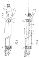
- the steering column of a motor vehicle comprises a steering shaft 1 which is mounted to rotate freely in a body tube 2.
- the body tube 2 is disposed in a support element 4 which is secured to the chassis of the motor vehicle.
- the tube-body 2 is adjustable in height and depth in the vertical plane, and is locked in the support element by an adjustment system 5 in position of said steering column.
- the device for positioning, during an impact, of a steering column of a motor vehicle comprises additional guide means for the body-tube 2.
- additional guide means act so that the angle of the steering shaft 1 and of the steering wheel with the horizontal plane, which is weaker after retraction of the steering wheel, in order to allow correct operation and under optimal conditions of a safety air cushion.
- This safety air cushion is more commonly known as an air bag, and this is the term which will be used in the following description.
- the additional guide means consist of an additional guide slide 8, which is arranged on the body-tube 2. More specifically, the additional guide slide 8 is arranged on a reinforcement square 3 integral with the body-tube 2. The additional guide slide 8 is arranged in the extension of the depth adjustment slide 6, of the adjustment system 5 in the position of the steering column.
- the adjustment system in position 5 also includes a height adjustment slide 7 arranged on the support element 4. According to the essential characteristic of the invention, the additional guide slide 8 is inclined relative to the depth adjustment slide 6 of an angle which allows correct operation of the air bag under optimal conditions after retraction of the steering column.
- the steering column is retracted by a pyrotechnic cylinder 20, which is controlled by a collision detector.
- the cylinder 21 of the pyrotechnic cylinder 20 is mounted on the support element 4, and the end 22 of the piston rod is connected to the tube-body 2.
- the detector collision pilot the pyrotechnic cylinder, so as to send the gas generated by the explosion to the piston to operate the tube-body 2.
- the additional guide means consist of an additional guide slide marked 9 which is arranged on the support element 4.
- This additional guide slide 9 on the support element 4 comprises two guide elements in the shape of a "U" 10 and 11, the guide element 10 being arranged at the top and the guide element 11 being arranged at the bottom. These two guide elements 10 and 11 are placed parallel to each other, and are arranged so as to be able to receive and hold a plate 12.
- the plate 12 is carried by the reinforcement square 3 of the tube- body 2 with which it is integral.
- the plate 12 is secured to the two guide elements 10 and 11 in U shape by fuse pins 13.
- the two guide elements 10 and 11 are inclined relative to the support element 4, by angle which allows the air bag to operate under optimal conditions, after retraction of the steering column. This retraction is made possible by the rupture of the fuse pins 13, which is caused by the shock. The retraction is guided by the sliding of the plate 12 in the two U-shaped guide elements 10 and 11.
Landscapes
- Engineering & Computer Science (AREA)
- Chemical & Material Sciences (AREA)
- Combustion & Propulsion (AREA)
- Transportation (AREA)
- Mechanical Engineering (AREA)
- Steering Controls (AREA)
- Air Bags (AREA)
Applications Claiming Priority (2)
| Application Number | Priority Date | Filing Date | Title |
|---|---|---|---|
| FR9605675 | 1996-05-03 | ||
| FR9605675A FR2748250B1 (fr) | 1996-05-03 | 1996-05-03 | Dispositif de positionnement, lors d'un choc, d'une colonne de direction de vehicule automobile |
Publications (2)
| Publication Number | Publication Date |
|---|---|
| EP0805093A1 true EP0805093A1 (de) | 1997-11-05 |
| EP0805093B1 EP0805093B1 (de) | 2003-04-09 |
Family
ID=9491894
Family Applications (1)
| Application Number | Title | Priority Date | Filing Date |
|---|---|---|---|
| EP97400966A Expired - Lifetime EP0805093B1 (de) | 1996-05-03 | 1997-04-29 | Posioniereinrichtung einer Kraftfahrzeug-Lenksäule bei einem Stoss |
Country Status (5)
| Country | Link |
|---|---|
| US (1) | US5769454A (de) |
| EP (1) | EP0805093B1 (de) |
| DE (1) | DE69720580T2 (de) |
| ES (1) | ES2192252T3 (de) |
| FR (1) | FR2748250B1 (de) |
Cited By (1)
| Publication number | Priority date | Publication date | Assignee | Title |
|---|---|---|---|---|
| US20230182803A1 (en) * | 2021-12-15 | 2023-06-15 | Steering Solutions Ip Holding Corporation | Automatic stow column |
Families Citing this family (16)
| Publication number | Priority date | Publication date | Assignee | Title |
|---|---|---|---|---|
| JP3396158B2 (ja) * | 1997-12-26 | 2003-04-14 | 富士機工株式会社 | ステアリングコラムのエネルギー吸収構造 |
| US5984355A (en) * | 1998-03-10 | 1999-11-16 | Chysler Corporation | Steering column angle |
| US7314234B2 (en) * | 1998-05-11 | 2008-01-01 | Thyssenkrupp Presta Ag | Steering column and adjustment method for a steering column |
| FR2780934B1 (fr) | 1998-07-13 | 2001-05-04 | Lemforder Nacam Sa | Dispositif de serrage a commande electrique pour un systeme de reglage en position d'un element par rapport a un autre element |
| GB9820337D0 (en) * | 1998-09-19 | 1998-11-11 | Rover Group | A steering wheel arrangement |
| GB9820342D0 (en) * | 1998-09-19 | 1998-11-11 | Rover Group | A steering wheel arrangement |
| GB9820340D0 (en) * | 1998-09-19 | 1998-11-11 | Rover Group | An air bag arrangement |
| US6317189B1 (en) * | 1998-12-29 | 2001-11-13 | Xerox Corporation | High-efficiency reflective liquid crystal display |
| SE9900985D0 (sv) * | 1999-03-18 | 1999-03-18 | Lars Sundholm | Säkerhetssystem vid ratt |
| JP3727004B2 (ja) * | 1999-09-10 | 2005-12-14 | 光洋精工株式会社 | 衝撃吸収式ステアリング装置及びこれに用いる取付部材 |
| US7942446B2 (en) | 2004-04-30 | 2011-05-17 | Nexteer (Beijing) Technology Co., Ltd. | Horizontal hybrid collapsing steering column |
| US20060273568A1 (en) * | 2005-06-01 | 2006-12-07 | Manwaring Marvin V | Adaptive energy absorber for steering column |
| US8863609B2 (en) | 2013-03-14 | 2014-10-21 | Steering Solutions Ip Holding Corporation | On-center single-sided clamp mechanism in steering column |
| US10207697B2 (en) * | 2015-12-21 | 2019-02-19 | Ford Global Technologies, Llc | Movable steering wheel for autonomous vehicle |
| JP6985918B2 (ja) * | 2017-12-18 | 2021-12-22 | 株式会社山田製作所 | ステアリング装置 |
| US10464591B2 (en) * | 2017-12-19 | 2019-11-05 | Thyssenkrupp Presta Ag | Automatically-stowed steering column assembly |
Citations (4)
| Publication number | Priority date | Publication date | Assignee | Title |
|---|---|---|---|---|
| GB2244032A (en) * | 1990-05-08 | 1991-11-20 | Torrington Co | Mechanism for absorbing impact energy transmitted through a vehicle steering column |
| EP0564898A2 (de) * | 1992-04-07 | 1993-10-13 | Lemfoerder Metallwaren Ag. | Lenksäule mit einem Sicherheitsglied für ein im Lenkrad mit einem aufblasbaren Gassack ausgerüstetes Kraftfahrzeug |
| EP0634314A1 (de) * | 1993-07-16 | 1995-01-18 | Ecia - Equipements Et Composants Pour L'industrie Automobile | Im Fall eines Stosses axial zurückziehbare Lenksäuleneinheit, insbesondere für ein Kraftfahrzeug |
| DE4421509A1 (de) * | 1994-06-20 | 1995-12-21 | Hs Tech & Design | Vorrichtung zum Zurückziehen einer Lenksäule |
Family Cites Families (5)
| Publication number | Priority date | Publication date | Assignee | Title |
|---|---|---|---|---|
| DE3433936A1 (de) * | 1984-09-15 | 1986-03-27 | Bayerische Motoren Werke AG, 8000 München | Sicherheitsvorrichtung fuer lenkanordnungen von kraftfahrzeugen |
| EP0332126B1 (de) * | 1988-03-08 | 1994-06-29 | Mazda Motor Corporation | Lenkvorrichtungs-Tragkonstruktion eines Kraftfahrzeuges |
| FR2713188B1 (fr) * | 1993-11-29 | 1996-02-23 | Nacam | Dispositif d'absorption d'énergie pour colonne de direction de véhicule automobile. |
| JPH08113148A (ja) * | 1994-10-19 | 1996-05-07 | Honda Motor Co Ltd | 車両のステアリングコラム支持構造 |
| US5507521A (en) * | 1995-02-27 | 1996-04-16 | Trw Vehicle Safety Systems Inc. | Automatic tilt mechanism for steering wheel with inflatable restraint |
-
1996
- 1996-05-03 FR FR9605675A patent/FR2748250B1/fr not_active Expired - Lifetime
-
1997
- 1997-04-29 ES ES97400966T patent/ES2192252T3/es not_active Expired - Lifetime
- 1997-04-29 EP EP97400966A patent/EP0805093B1/de not_active Expired - Lifetime
- 1997-04-29 DE DE69720580T patent/DE69720580T2/de not_active Expired - Fee Related
- 1997-04-30 US US08/841,686 patent/US5769454A/en not_active Expired - Fee Related
Patent Citations (4)
| Publication number | Priority date | Publication date | Assignee | Title |
|---|---|---|---|---|
| GB2244032A (en) * | 1990-05-08 | 1991-11-20 | Torrington Co | Mechanism for absorbing impact energy transmitted through a vehicle steering column |
| EP0564898A2 (de) * | 1992-04-07 | 1993-10-13 | Lemfoerder Metallwaren Ag. | Lenksäule mit einem Sicherheitsglied für ein im Lenkrad mit einem aufblasbaren Gassack ausgerüstetes Kraftfahrzeug |
| EP0634314A1 (de) * | 1993-07-16 | 1995-01-18 | Ecia - Equipements Et Composants Pour L'industrie Automobile | Im Fall eines Stosses axial zurückziehbare Lenksäuleneinheit, insbesondere für ein Kraftfahrzeug |
| DE4421509A1 (de) * | 1994-06-20 | 1995-12-21 | Hs Tech & Design | Vorrichtung zum Zurückziehen einer Lenksäule |
Cited By (2)
| Publication number | Priority date | Publication date | Assignee | Title |
|---|---|---|---|---|
| US20230182803A1 (en) * | 2021-12-15 | 2023-06-15 | Steering Solutions Ip Holding Corporation | Automatic stow column |
| US11958525B2 (en) * | 2021-12-15 | 2024-04-16 | Steering Solutions Ip Holding Corporation | Automatic stow column |
Also Published As
| Publication number | Publication date |
|---|---|
| EP0805093B1 (de) | 2003-04-09 |
| ES2192252T3 (es) | 2003-10-01 |
| DE69720580D1 (de) | 2003-05-15 |
| US5769454A (en) | 1998-06-23 |
| FR2748250B1 (fr) | 1998-06-26 |
| DE69720580T2 (de) | 2004-02-19 |
| FR2748250A1 (fr) | 1997-11-07 |
Similar Documents
| Publication | Publication Date | Title |
|---|---|---|
| EP0805093A1 (de) | Posioniereinrichtung einer Kraftfahrzeug-Lenksäule bei einem Stoss | |
| US6419269B1 (en) | Locking system for adjustable position steering column | |
| EP0805092B1 (de) | Bei einem Stoss aktive Rückzugeinrichtung einer Kraftfahrzeug-Lenksäule | |
| US20050006891A1 (en) | Steering column supporting apparatus | |
| HUE035481T2 (en) | Collision-absorbing vehicle, collision absorbing system and procedure | |
| JP2006526536A (ja) | 車両座席用のベルトロック装置 | |
| US5984355A (en) | Steering column angle | |
| GB2312149A (en) | Belt force limiter for a vehicle seat belt | |
| US20020059848A1 (en) | Steering device for a motor vehicle | |
| EP2969705B1 (de) | Kraftfahrzeug mit mittel zur positionierung einer zusammenschiebbaren lenksäule | |
| EP1042139B1 (de) | Aus einer inaktiven in eine aktive stellung versetzbare vorrichtung zur verhinderung des abtauchens | |
| EP0474400B1 (de) | Lenksäule versehen mit einem energieabsorbierenden System | |
| US8281684B2 (en) | Steering column arrangement for a motor vehicle | |
| JPH09169279A (ja) | 自動車用ステアリングコラム | |
| JP2005088879A (ja) | エネルギー吸収ブラケット | |
| FR2881707A1 (fr) | Dispositif d'absorption instantanee d'energie d'une colonne de direction de vehicule automobile | |
| EP3600974A1 (de) | Airbagvorrichtung für innenauskleidungselement eines kraftfahrzeuges | |
| JPH03567A (ja) | 自動車のステアリング支持構造 | |
| FR3102715A1 (fr) | Pare-soleil pour véhicule automobile et véhicule automobile comportant un tel équipement | |
| FR3129894A1 (fr) | Coussin gonflable de sécurité de type frontal pour véhicule automobile | |
| FR3072059B1 (fr) | Systeme d’amortissement d’un siege de vehicule. | |
| KR20070075111A (ko) | 텔레스 제 2 기어와 텔레스 제 1 기어를 구비한 텔레스코프조향장치 | |
| FR3165842A1 (fr) | Volant de direction pour véhicule automobile comprenant un airbag déporté | |
| FR2890018A1 (fr) | Module de toit escamotable possedant un dispositif de securite | |
| FR3158082A1 (fr) | Dispositif de sécurité à appui-tête maintenu par des sangles. |
Legal Events
| Date | Code | Title | Description |
|---|---|---|---|
| PUAI | Public reference made under article 153(3) epc to a published international application that has entered the european phase |
Free format text: ORIGINAL CODE: 0009012 |
|
| AK | Designated contracting states |
Kind code of ref document: A1 Designated state(s): DE ES GB IT |
|
| 17P | Request for examination filed |
Effective date: 19971110 |
|
| 17Q | First examination report despatched |
Effective date: 19991025 |
|
| GRAH | Despatch of communication of intention to grant a patent |
Free format text: ORIGINAL CODE: EPIDOS IGRA |
|
| RAP1 | Party data changed (applicant data changed or rights of an application transferred) |
Owner name: NACAM FRANCE SA |
|
| GRAH | Despatch of communication of intention to grant a patent |
Free format text: ORIGINAL CODE: EPIDOS IGRA |
|
| GRAA | (expected) grant |
Free format text: ORIGINAL CODE: 0009210 |
|
| AK | Designated contracting states |
Designated state(s): DE ES GB IT |
|
| REG | Reference to a national code |
Ref country code: GB Ref legal event code: FG4D Free format text: NOT ENGLISH |
|
| PGFP | Annual fee paid to national office [announced via postgrant information from national office to epo] |
Ref country code: GB Payment date: 20030415 Year of fee payment: 7 |
|
| PGFP | Annual fee paid to national office [announced via postgrant information from national office to epo] |
Ref country code: ES Payment date: 20030422 Year of fee payment: 7 |
|
| PGFP | Annual fee paid to national office [announced via postgrant information from national office to epo] |
Ref country code: DE Payment date: 20030423 Year of fee payment: 7 |
|
| GBT | Gb: translation of ep patent filed (gb section 77(6)(a)/1977) |
Effective date: 20030409 |
|
| REG | Reference to a national code |
Ref country code: ES Ref legal event code: FG2A Ref document number: 2192252 Country of ref document: ES Kind code of ref document: T3 |
|
| PLBE | No opposition filed within time limit |
Free format text: ORIGINAL CODE: 0009261 |
|
| STAA | Information on the status of an ep patent application or granted ep patent |
Free format text: STATUS: NO OPPOSITION FILED WITHIN TIME LIMIT |
|
| 26N | No opposition filed |
Effective date: 20040112 |
|
| PG25 | Lapsed in a contracting state [announced via postgrant information from national office to epo] |
Ref country code: GB Free format text: LAPSE BECAUSE OF NON-PAYMENT OF DUE FEES Effective date: 20040429 |
|
| PG25 | Lapsed in a contracting state [announced via postgrant information from national office to epo] |
Ref country code: ES Free format text: LAPSE BECAUSE OF NON-PAYMENT OF DUE FEES Effective date: 20040430 |
|
| PG25 | Lapsed in a contracting state [announced via postgrant information from national office to epo] |
Ref country code: DE Free format text: LAPSE BECAUSE OF NON-PAYMENT OF DUE FEES Effective date: 20041103 |
|
| GBPC | Gb: european patent ceased through non-payment of renewal fee |
Effective date: 20040429 |
|
| PG25 | Lapsed in a contracting state [announced via postgrant information from national office to epo] |
Ref country code: IT Free format text: LAPSE BECAUSE OF NON-PAYMENT OF DUE FEES;WARNING: LAPSES OF ITALIAN PATENTS WITH EFFECTIVE DATE BEFORE 2007 MAY HAVE OCCURRED AT ANY TIME BEFORE 2007. THE CORRECT EFFECTIVE DATE MAY BE DIFFERENT FROM THE ONE RECORDED. Effective date: 20050429 |
|
| REG | Reference to a national code |
Ref country code: ES Ref legal event code: FD2A Effective date: 20040430 |