EP0805076B1 - Vorrichtung zum Positionieren eines Sicherheitsgurt-Aufrollers in einem Kraftfahrzeug - Google Patents
Vorrichtung zum Positionieren eines Sicherheitsgurt-Aufrollers in einem Kraftfahrzeug Download PDFInfo
- Publication number
- EP0805076B1 EP0805076B1 EP19970400987 EP97400987A EP0805076B1 EP 0805076 B1 EP0805076 B1 EP 0805076B1 EP 19970400987 EP19970400987 EP 19970400987 EP 97400987 A EP97400987 A EP 97400987A EP 0805076 B1 EP0805076 B1 EP 0805076B1
- Authority
- EP
- European Patent Office
- Prior art keywords
- receiving member
- retractor
- reel
- opening
- support structure
- Prior art date
- Legal status (The legal status is an assumption and is not a legal conclusion. Google has not performed a legal analysis and makes no representation as to the accuracy of the status listed.)
- Expired - Lifetime
Links
- 239000000853 adhesive Substances 0.000 claims description 2
- 230000001070 adhesive effect Effects 0.000 claims description 2
- 230000000903 blocking effect Effects 0.000 claims 1
- 210000000056 organ Anatomy 0.000 description 5
- 241000920340 Pion Species 0.000 description 2
- 230000015556 catabolic process Effects 0.000 description 2
- 238000006731 degradation reaction Methods 0.000 description 2
- 235000014443 Pyrus communis Nutrition 0.000 description 1
- 238000004140 cleaning Methods 0.000 description 1
- 239000003086 colorant Substances 0.000 description 1
- 230000006866 deterioration Effects 0.000 description 1
- 239000003292 glue Substances 0.000 description 1
- 238000009434 installation Methods 0.000 description 1
- 238000012423 maintenance Methods 0.000 description 1
- 238000004519 manufacturing process Methods 0.000 description 1
- 239000008188 pellet Substances 0.000 description 1
- 238000003466 welding Methods 0.000 description 1
Images


Classifications
-
- B—PERFORMING OPERATIONS; TRANSPORTING
- B60—VEHICLES IN GENERAL
- B60R—VEHICLES, VEHICLE FITTINGS, OR VEHICLE PARTS, NOT OTHERWISE PROVIDED FOR
- B60R22/00—Safety belts or body harnesses in vehicles
- B60R22/34—Belt retractors, e.g. reels
Definitions
- the subject of the present invention is a belt retractor positioning device safety in a motor vehicle.
- some elements are equipped with means of assistance during assembly allowing pre-positioning and pre-maintenance of these elements on the support structures.
- reels seat belt which have a structure of support in which a coil is rotatably mounted reel strap holder and intended to be fixed on a receiving member secured to the vehicle body.
- belt reels which include either a nut secured to the reel support structure or either a pre-positioned screw on the receiving member of this reel for example by a cardboard washer.
- a positioning device for a belt rewinder safety in a motor vehicle of the type comprising a support structure in which is rotatably mounted a reel carrying strap and intended to be fixed to a receiving member secured to the body of the vehicle.
- the support structure has a centering cleat and a threaded orifice intended to receive an element of screwing on the receiving device.
- reels have no means to avoid mounting a left winder to right of the vehicle or vice versa or a reel front to back or vice versa.
- the object of the invention is to avoid these drawbacks by proposing a device for positioning a reel seat belt in a motor vehicle which allows, by simple means, to place unambiguously possible the reel on its receiving member before its fixing and fix it definitively by movements simple and fast.
- the invention therefore relates to a device for positioning of a seat belt retractor in a motor vehicle, of the type comprising a support structure in which is mounted in rotation of a reel strap reel and intended to be fixed on a receiving member secured to the vehicle body, characterized in that the support structure has at least one screw-nut assembly pre-mounted on said structure support and cooperating with a cut out in the receiving member for the pre-assembly of said reel before fixing on the receiving device and for the fixing of this reel and in that it comprises polarizing bodies formed by a shape opening oblong formed in the receiving member and by a relief element arranged on the support structure of the reel and cooperating with said opening for placing said reel on said receiving member before fixing.
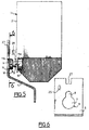
- FIG. 1 The figures show schematically a seat belt retractor 1 which comprises a support structure 2 in which is mounted, in a conventional manner, a strap-carrying coil 3, (Figs. 5 and 6), connected to known locking security means strap 4 and return means of said strap 4 in the wound position on said reel 3.
- the support structure 2 of the reel 1 is intended to be fixed to a receiving member 5 secured to the body of the motor vehicle.
- the support structure 2 of the reel 1 comprises at least one screw-nut assembly 10 pre-assembled on said support structure 2 and cooperating with a cutout 6 made in the receiving member 5 for the pre-assembly of said reel 1 before fixing it on said receiving member 5 and for fixing definitive of this reel 1.
- This screw-nut assembly 10 is made up, on the one hand, of a screw 11 comprising a threaded rod 11a and a head 11b and, on the other hand, a nut 12 integral of the support structure 2 of the reel 1.
- This nut 12 is fixed for example by welding on the face of the supporting structure 2 opposite to that intended to be applied to the receiving device 5.
- the manufacturer of this reel 1 preposition the screw 11 in the nut 12 so so that the head 11b of this screw 11 cleans with the support structure 2 free space on the order of 10mm.
- this screw 11 is immobilized relative to the structure of support 2 of the reel 1, for example by at least one glue point 13 deposited on the rod 11a of said screw 11.
- the cutout 6 formed in the receiving member 5 has for example the shape of a pear and is formed by a first opening 7 of width greater than the head 11b of the screw 11 and through a second opening 8 opening into the first opening 7 and of width between the width of the rod 11a ce the screw 11 and the width of the head 11b of said screw 11.
- the second opening 8 is arranged above the first opening 7 and in the axis of said first opening 7.
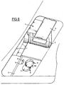
- the positioning device has left-right or front-rear polarizing members for mounting the reel 1 on the reception 5 and means for holding the reel 1 on the receiving member 5 before its final fixing on said receiving member 5.
- the polarizing bodies and the holding means are formed by the same elements.
- the keying and holding bodies are formed by an opening 9 for example of shape oblong formed in the receiving member 5 and by a relief element 14 for attachment arranged on the support structure 2 of the reel 1 and intended for cooperate with said opening 9.
- This relief element 14 for attachment is formed for example by a lug, a pin or a hook.
- the relief element 14 for attachment is constituted by a hook.
- the positioning device has left-right or front-rear polarizing members for mounting the reel 1 on the reception 5 and means for holding this reel 1 on the receiving member 5 before its final fixing on said receiving member 5 which are constituted by elements different from those constituting the keying bodies.
- the polarizing members are formed by an opening 15 for example of oblong shape formed in the organ of reception 5 and by a relief element 16 arranged on the support structure 2 of the reel 1 and intended for cooperate with said opening 15.
- the holding means are formed by an opening 17 formed for example at the upper part of the receiving member 5 and by a relief element 18 for attachment arranged on the structure support 2 of the reel 1 and intended to cooperate with said opening 17.
- the relief element 16 is formed for example by a lug, a pawn or a leg and the element in relief 18 of attachment is formed for example by a hook or a T-shaped leg
- the element in relief 16 is formed by a pin and the element in relief 18 hooking is formed by a T-shaped tab.
- the opening 17 has the shape of a T in the plane of the receiving member 5.
- the positioning device has left-right or front-rear polarizing members for mounting the reel 1 on the reception 5 and means for holding this reel 1 on the receiving member 5 before its final fixing on said receiving member 5 which are constituted by elements different from those constituting the keying bodies.
- the polarizing members are formed by an opening 25 for example of oblong shape formed in the organ of reception 5 and by a relief element 26 arranged on the support structure 2 of the reel 1 and intended for cooperate with said opening 15.
- the holding means are formed by an opening 27 formed for example at the upper part of the receiving member 5 and by a relief element 28 for attachment arranged on the structure support 2 of the reel 1 and intended to cooperate with said opening 27.
- the relief element 26 is formed for example by a lug, a pawn or a leg and the element in relief 28 hooking is formed for example by a hook or a T-shaped leg
- the element in relief 26 is formed by a pin and the element in relief 28 hooking is formed by a T-shaped tab.
- the opening 27 is formed in this embodiment by a notch of determined height.
- the mounting of the reel 1 on the reception 3 is carried out as follows.
- the operator takes, the reel 1 whose support structure 2 is pre-equipped with the screw- nut assembly 10 and slides this reel 1 behind the receiving member 5 so as to introduce the head 11b of the screw 11 into the first opening 7 of the cutout 6 formed in the receiving member 5, as shown in FIG. 5.
- the reel 1 is therefore kept in its place final and screw 11 can be tightened by Ea naval to be fixed definitively this reel 1 on the receiving member 5.
- the operator slides up the reel 1 so as to introduce the pin 16 into the opening 15 and it serves the screw 11 in order to fix definitively the reel 1 on the receiving member 5.
- the operator lowers the reel slightly to introduce the T-shaped tab 28 into the opening 27 and it serves the screw 11 to fix permanently the reel 1 on the support member 5.
- the positioning device according to the invention therefore makes it possible, by simple means, to position and maintain the reel on its organ of reception before its final fixing and to fix this reel avoiding the operator manipulations tedious and in particular simultaneous manipulations the fixing screw and a screwdriver.
- the positioning device prevents degradation of the organs of fixing at the time of screwing by prepositioning screw and nut and prevents the operator from mounting a right element to the left, a front element to the rear or vice versa, while allowing assembly to be carried out in minimum time.
Landscapes
- Engineering & Computer Science (AREA)
- Mechanical Engineering (AREA)
- Automotive Seat Belt Assembly (AREA)
- Emergency Lowering Means (AREA)
Claims (12)
- Vorrichtung zum Positionieren eines Sicherheitsgurt-Aufrollers (1) in einem Kraftfahrzeug der Art mit einer Trägerstruktur (2), in welcher eine Gurtrolle (3) des Aufrollers (1) drehbar montiert ist, die dafür bestimmt st, an einem Aufnahmeorgan (5) befestigt zu werden, welches einstückig mit der Karosserie ausgebildet ist, dadurch gekennzeichnet, dass die Trägerstruktur (2) mindestens einen auf der Trägerstruktur (2) vormontierten Schraube-Mutter-Satz (10, 11, 12) aufweist, der mit einem Ausschnitt (6) zusammenwirkt, der in dem Aufnahmeorgan (5) zur Vormontage des Aufrollers (1) vor seirer Befestigung an dem Aufnahmeorgan (5) und für die Befestigung dieses Aufrollers auf dem Aufnahmeorgan (5) vorgesehen ist, und daß sie eindeutige Anordnungs-Organe aufweist, die durch eine längliche Öffnung (9, 15, 25) in dem Aufnahmeorgan (5) und durch ein auf der Trägerstruktur (2) des Aufrollers (1) angebrachtes vorspringendes Element (14, 16, 26) ausgebildet sind, und welche mit der Öffnung (9, 15 ,25) zusammenwirken, um den Aufroller (1) auf dem Aufnahmeorgan (5) vor seiner Befestigung anzuordnen.
- Vorrichtung gemäss Anspruch 1, dadurch gekennzeichnet, dass die Mutter (12) mit der Trägerstruktur (2) des Aufrollers (1) einstückig ausgebildet ist.
- Vorrichtung gemäss Anspruch 1, dadurch gekennzeichnet, c ass der Kopf (11b) der Schraube (11) zusammen mit der Trägerstruktur (2) des Aufrollers (1) einen freien Raum bildet.
- Vorrichtung gemäss den Ansprüchen 1 und 3, dadurch gekennzeichnet, dass während des Beförderungsbetriebs des Aufrollers (1) die Schraube in Bezug auf die Trägerstruktur (2) des Aufrollers (1) unbeweglich gemacht wird.
- Vorrichtung gemäss Anspruch 4, dadurch gekennzeichnet, dass die Schraube (11) mittels wenigstens eines Klebepunktes (13) am Schaft (11a) der Schraube (11) unbeweglich gemacht wird.
- Vorrichtung gemäss Anspruch 1, dadurch gekennzeichnet, dass der in dem Aufnahmeorgan (5) vorgesehene Ausschnitt (6) von einer ersten Öffnung (7), die grösser als der Kopf (11b) der Schraube (11) ist, und einer zweiten Öffnung (8), die in die erste Öffnung mündet und deren Grösse zwischen der Grösse des Schaftes (11a) der Schraube (11) und der Grösse des Kopfes (11b) der besagten Schraube (11) liegt, gebildet ist.
- Vorrichtung gemäss Anspruch 1, dadurch gekennzeichnet, cass sie Vorrichtungen zum Halten des Aufrollers (1) an dem Aufnahmeorgan (5) vor seiner endgültigen Befestigung an dem Aufnahmeorgan (5) aufweist.
- Vorrichtung gemäss Anspruch 7, dadurch gekennzeichnet, cass die Vorrichtungen zum Halten durch ein vorspringendes Element (14) gebildet sind, welche ein vorspringendes Einhak-Element bilden.
- Vorrichtung gemäss Anspruch 8, dadurch gekennzeichnet, dass das Einhak-Element (14) durch einen Haken, einen Zapfen oder einen Metallstift gebildet ist.
- Vorrichtung gemäss Anspruch 1, dadurch gekennzeichnet, dass das vorspringende Element (16, 26) durch einen Haken, einen Metallstift oder ein Anhängsel gebildet ist.
- Vorrichtung gemäss Anspruch 7, dadurch gekennzeichnet, dass die Haltevorrichtungen aus einer Öffnung (17, 27), welche in dem Aufnahmeorgan (5) vorgesehen ist, und einem vorspringenden Einhak-Element (18, 28), welches an der Trägerstruktur (2) des Aufrollers (1) angebracht ist und mit der Öffnung (17, 27) zusammenwirkt, gebildet sind.
- Vorrichtung gemäss Anspruch 11, dadurch gekennzeichnet dass das vorspringende Einhak-Element (18, 28) durch einen Haken oder ein Anhängsel in T-Form gebildet ist.
Applications Claiming Priority (2)
| Application Number | Priority Date | Filing Date | Title |
|---|---|---|---|
| FR9605512 | 1996-05-02 | ||
| FR9605512A FR2748242B1 (fr) | 1996-05-02 | 1996-05-02 | Dispositif de positionnement d'un enrouleur de ceinture de securite dans un vehicule automobile |
Publications (2)
| Publication Number | Publication Date |
|---|---|
| EP0805076A1 EP0805076A1 (de) | 1997-11-05 |
| EP0805076B1 true EP0805076B1 (de) | 2001-11-28 |
Family
ID=9491777
Family Applications (1)
| Application Number | Title | Priority Date | Filing Date |
|---|---|---|---|
| EP19970400987 Expired - Lifetime EP0805076B1 (de) | 1996-05-02 | 1997-04-30 | Vorrichtung zum Positionieren eines Sicherheitsgurt-Aufrollers in einem Kraftfahrzeug |
Country Status (3)
| Country | Link |
|---|---|
| EP (1) | EP0805076B1 (de) |
| DE (1) | DE69708498T2 (de) |
| FR (1) | FR2748242B1 (de) |
Families Citing this family (1)
| Publication number | Priority date | Publication date | Assignee | Title |
|---|---|---|---|---|
| DE19842592C1 (de) * | 1998-09-17 | 2000-05-31 | Daimler Chrysler Ag | Anordnung zur Befestigung einer Baugruppe mit mindestens einer an dieser Baugruppe vormontierten Befestigungsschraube an einem Träger mit einer zugeordneten Öffnung |
Family Cites Families (3)
| Publication number | Priority date | Publication date | Assignee | Title |
|---|---|---|---|---|
| DE1949485U (de) * | 1966-07-26 | 1966-11-10 | Reiche & Co | Stossverbindungsvorrichtung fuer winklig zueinander verlaufende rohre, insbesondere profilrohre. |
| DE3318740A1 (de) * | 1983-05-21 | 1984-11-29 | Adam Opel AG, 6090 Rüsselsheim | Kraftfahrzeug mit einem gurtaufroller fuer ein sicherheitsgurtsystem |
| DE3343104A1 (de) * | 1983-11-29 | 1985-06-05 | Autoliv GmbH, 2200 Elmshorn | Vorrichtung zum befestigen des gehaeuses einer automatischen aufrolleinrichtung fuer sicherheitsgurte und deren end- und umlenkbeschlaege |
-
1996
- 1996-05-02 FR FR9605512A patent/FR2748242B1/fr not_active Expired - Fee Related
-
1997
- 1997-04-30 DE DE1997608498 patent/DE69708498T2/de not_active Expired - Fee Related
- 1997-04-30 EP EP19970400987 patent/EP0805076B1/de not_active Expired - Lifetime
Also Published As
| Publication number | Publication date |
|---|---|
| FR2748242B1 (fr) | 1998-07-31 |
| DE69708498D1 (de) | 2002-01-10 |
| EP0805076A1 (de) | 1997-11-05 |
| DE69708498T2 (de) | 2002-08-29 |
| FR2748242A1 (fr) | 1997-11-07 |
Similar Documents
| Publication | Publication Date | Title |
|---|---|---|
| FR2926858A1 (fr) | Dispositif de fixation d'un premier sous-ensemble a un second sous-ensemble d'un vehicule automobile. | |
| EP0260170B1 (de) | Auf einer festen Fahrzeugwand befestigter Bremskraftverstärker | |
| FR2857314A1 (fr) | Dispositif de fixation des parties laterales en forme de crosse du pare-chocs avant d'un vehicule automobile aux ailes de ce dernier | |
| EP2181899A1 (de) | Befestigungsvorrichtung für einen Sicherheitsgurt, und Bodengruppe eines Kraftfahrzeugs, welche mit einer solchen Vorrichtung ausgestattet ist. | |
| FR2668435A1 (fr) | Porte-velo de voiture destine a etre fixe a l'arriere d'un vehicule pour assurer le transport d'une bicyclette. | |
| EP0805076B1 (de) | Vorrichtung zum Positionieren eines Sicherheitsgurt-Aufrollers in einem Kraftfahrzeug | |
| EP0371831B1 (de) | Montageeinrichtung für einen Servomotor auf einer Fahrzeugspritzwand | |
| EP0497636B1 (de) | Befestigungseinrichtung einer Stossstange eines Fahrzeuges | |
| FR2841864A1 (fr) | Element structurel comprenant un ecrou de fixation a un montant et vehicule automobile correspondant | |
| EP2678212A1 (de) | Vorrichtung zur befestigung eines reserverades eines fahrzeuges | |
| FR2921988A1 (fr) | Piece rapportee avec dispositif de fixation integre et procede de fixation d'une telle piece | |
| FR2821813A1 (fr) | Face avant technique de vehicule automobile comprenant un module de refroidissement | |
| EP4232663B1 (de) | Vorrichtung zur befestigung eines positionsverstellbaren schlosses und anordnung mit der vorrichtung und dem schloss | |
| FR2929223A1 (fr) | Fixation d'une piece fonctionnelle a une partie de caisse de structure de vehicule. | |
| EP1032510B1 (de) | Einstellbare montagevorrichtung für signal-oder beleuchtungseinrichtung und dazugehöriges strukturelement für kraftfahrzeuge | |
| EP0459849B1 (de) | Einstellbare Befestigungsvorrichtung für eine Fahrzeugstossstange | |
| EP2017408A1 (de) | Vorrichtung zur Vorpositionierung eines Schliessbügels, der mit dem Schloss eines Kraftfahrzeugsflügels zusammenwirken soll, und Kraftfahrzeug mit mindestens einer solchen Vorrichtung | |
| EP4527690B1 (de) | Karosserie für ein strassenfahrzeug zum transport von gütern mit einem spannsystem | |
| FR2784955A1 (fr) | Dispositif de fixation d'un element exterieur de carrosserie sur une structure de vehicule, et vehicule comportant un tel dispositif | |
| EP3863894B1 (de) | Grundplatte für einen sicherheitsgurtaufroller und kraftfahrzeug mit einem solchen aufroller | |
| FR2882798A1 (fr) | Dispositif pour la fixation temporaire permettant le reglage d'un module mecanique sur un support | |
| FR2919247A3 (fr) | Dispositif de fixation d'un fermoir de boucle de ceinture d'un vehicule automobile et siege adapte pour recevoir un tel dispositif de fixation. | |
| EP3678894B1 (de) | Befestigungsvorrichtung eines abnehmbaren sitzes an einem kraftfahrzeugboden | |
| EP1319532B1 (de) | Anordnung zur Befestigung an einem Hohlträger von einer Kupplungsvorrichtung an einem Schlepp- oder Verankerungsteil eines Kraftfahrzeuges | |
| EP4527690A1 (de) | Karosserie für ein strassenfahrzeug zum transport von gütern mit einem spannsystem |
Legal Events
| Date | Code | Title | Description |
|---|---|---|---|
| PUAI | Public reference made under article 153(3) epc to a published international application that has entered the european phase |
Free format text: ORIGINAL CODE: 0009012 |
|
| AK | Designated contracting states |
Kind code of ref document: A1 Designated state(s): DE ES GB IT PT |
|
| 17P | Request for examination filed |
Effective date: 19980425 |
|
| 17Q | First examination report despatched |
Effective date: 19990812 |
|
| GRAG | Despatch of communication of intention to grant |
Free format text: ORIGINAL CODE: EPIDOS AGRA |
|
| GRAG | Despatch of communication of intention to grant |
Free format text: ORIGINAL CODE: EPIDOS AGRA |
|
| GRAH | Despatch of communication of intention to grant a patent |
Free format text: ORIGINAL CODE: EPIDOS IGRA |
|
| GRAH | Despatch of communication of intention to grant a patent |
Free format text: ORIGINAL CODE: EPIDOS IGRA |
|
| GRAA | (expected) grant |
Free format text: ORIGINAL CODE: 0009210 |
|
| AK | Designated contracting states |
Kind code of ref document: B1 Designated state(s): DE ES GB IT PT |
|
| PG25 | Lapsed in a contracting state [announced via postgrant information from national office to epo] |
Ref country code: IT Free format text: LAPSE BECAUSE OF FAILURE TO SUBMIT A TRANSLATION OF THE DESCRIPTION OR TO PAY THE FEE WITHIN THE PRESCRIBED TIME-LIMIT;WARNING: LAPSES OF ITALIAN PATENTS WITH EFFECTIVE DATE BEFORE 2007 MAY HAVE OCCURRED AT ANY TIME BEFORE 2007. THE CORRECT EFFECTIVE DATE MAY BE DIFFERENT FROM THE ONE RECORDED. Effective date: 20011128 |
|
| REG | Reference to a national code |
Ref country code: GB Ref legal event code: IF02 |
|
| REF | Corresponds to: |
Ref document number: 69708498 Country of ref document: DE Date of ref document: 20020110 |
|
| GBT | Gb: translation of ep patent filed (gb section 77(6)(a)/1977) |
Effective date: 20020128 |
|
| PG25 | Lapsed in a contracting state [announced via postgrant information from national office to epo] |
Ref country code: PT Free format text: LAPSE BECAUSE OF FAILURE TO SUBMIT A TRANSLATION OF THE DESCRIPTION OR TO PAY THE FEE WITHIN THE PRESCRIBED TIME-LIMIT Effective date: 20020228 |
|
| PG25 | Lapsed in a contracting state [announced via postgrant information from national office to epo] |
Ref country code: ES Free format text: LAPSE BECAUSE OF FAILURE TO SUBMIT A TRANSLATION OF THE DESCRIPTION OR TO PAY THE FEE WITHIN THE PRESCRIBED TIME-LIMIT Effective date: 20020530 |
|
| PLBE | No opposition filed within time limit |
Free format text: ORIGINAL CODE: 0009261 |
|
| STAA | Information on the status of an ep patent application or granted ep patent |
Free format text: STATUS: NO OPPOSITION FILED WITHIN TIME LIMIT |
|
| 26N | No opposition filed | ||
| REG | Reference to a national code |
Ref country code: GB Ref legal event code: 746 Effective date: 20070117 |
|
| PGFP | Annual fee paid to national office [announced via postgrant information from national office to epo] |
Ref country code: GB Payment date: 20080326 Year of fee payment: 12 |
|
| PGFP | Annual fee paid to national office [announced via postgrant information from national office to epo] |
Ref country code: DE Payment date: 20090504 Year of fee payment: 13 |
|
| GBPC | Gb: european patent ceased through non-payment of renewal fee |
Effective date: 20090430 |
|
| PG25 | Lapsed in a contracting state [announced via postgrant information from national office to epo] |
Ref country code: GB Free format text: LAPSE BECAUSE OF NON-PAYMENT OF DUE FEES Effective date: 20090430 |
|
| PG25 | Lapsed in a contracting state [announced via postgrant information from national office to epo] |
Ref country code: DE Free format text: LAPSE BECAUSE OF NON-PAYMENT OF DUE FEES Effective date: 20101103 |