EP0805076A1 - Vorrichtung zum Positionieren eines Sicherheitsgurt-Aufrollers in einem Kraftfahrzeug - Google Patents
Vorrichtung zum Positionieren eines Sicherheitsgurt-Aufrollers in einem Kraftfahrzeug Download PDFInfo
- Publication number
- EP0805076A1 EP0805076A1 EP97400987A EP97400987A EP0805076A1 EP 0805076 A1 EP0805076 A1 EP 0805076A1 EP 97400987 A EP97400987 A EP 97400987A EP 97400987 A EP97400987 A EP 97400987A EP 0805076 A1 EP0805076 A1 EP 0805076A1
- Authority
- EP
- European Patent Office
- Prior art keywords
- reel
- opening
- receiving member
- screw
- support structure
- Prior art date
- Legal status (The legal status is an assumption and is not a legal conclusion. Google has not performed a legal analysis and makes no representation as to the accuracy of the status listed.)
- Granted
Links
- 239000000853 adhesive Substances 0.000 claims abstract description 3
- 230000001070 adhesive effect Effects 0.000 claims abstract description 3
- 210000000056 organ Anatomy 0.000 description 4
- 241000920340 Pion Species 0.000 description 2
- 235000014443 Pyrus communis Nutrition 0.000 description 1
- 230000015556 catabolic process Effects 0.000 description 1
- 239000003086 colorant Substances 0.000 description 1
- 238000006731 degradation reaction Methods 0.000 description 1
- 230000006866 deterioration Effects 0.000 description 1
- 239000003292 glue Substances 0.000 description 1
- 238000009434 installation Methods 0.000 description 1
- 238000012423 maintenance Methods 0.000 description 1
- 238000004519 manufacturing process Methods 0.000 description 1
- 239000002184 metal Substances 0.000 description 1
- 238000003466 welding Methods 0.000 description 1
Images
Classifications
-
- B—PERFORMING OPERATIONS; TRANSPORTING
- B60—VEHICLES IN GENERAL
- B60R—VEHICLES, VEHICLE FITTINGS, OR VEHICLE PARTS, NOT OTHERWISE PROVIDED FOR
- B60R22/00—Safety belts or body harnesses in vehicles
- B60R22/34—Belt retractors, e.g. reels
Definitions
- the present invention relates to a device for positioning a seat belt retractor in a motor vehicle.
- these elements are provided with polarizing systems authorizing the mounting of said elements only at well determined locations.
- seat belt retractors which include a support structure in which a reel-carrying strap reel is mounted for rotation and intended to be fixed to a receiving member secured to the vehicle body .
- Safety belt retractors are known, the support structure of which comprises a metal tab cooperating with an opening in the support member so as to pre-maintain the retractor in a position close to its final position before the fixing members are fitted. definitive.
- the operator is obliged to position the fastening elements on the support structure of the reel and on the receiving member, then maintain and assemble them which can lead to damage to these elements, in particular when they consist of a set screw nut.
- Safety belt retractors are also known which comprise either a nut integral with the support structure of the retractor or a screw prepositioned on the receiving member of this retractor, for example by a cardboard washer.
- reels have no means of avoiding the mounting of a left reel on the right of the vehicle or vice versa or a front reel at the rear or vice versa.
- the object of the invention is to avoid these drawbacks by proposing a device for positioning a seat belt retractor in a motor vehicle which makes it possible, by simple means, to place the retractor without ambiguity possible on its receiving member. before fixing and to fix it definitively by simple and fast movements.
- the invention therefore relates to a device for positioning a seat belt retractor in a motor vehicle, of the type comprising a support structure in which a reel strap reel is mounted for rotation and intended to be fixed to a receiving member secured to the vehicle body, characterized in that the support structure comprises at least one screw assembly nut pre-assembled on said support structure and cooperating with a cutout made in the receiving member for the pre-assembly of said reel before its attachment to the receiving member and for the attachment of this reel.
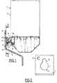
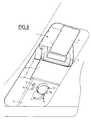
- a seat belt retractor 1 which comprises a support structure 2 in which is mounted, in a conventional manner, a strap-carrying reel 3, (Figs. 5 and 6), connected to means known safety devices for locking the strap 4 and to means for returning said strap 4 to the wound position on said reel 3.
- the support structure 2 of the reel 1 is intended to be fixed to a receiving member 5 secured to the body of the motor vehicle.
- the support structure 2 of the reel 1 comprises at least one screw-nut assembly 10 pre-assembled on said support structure 2 and cooperating with a cutout 6 made in the receiving member 5 for the pre-assembly of said front reel 1 its attachment to said receiving member 5 and for the final attachment of this reel 1.
- This screw-nut assembly 10 consists, on the one hand, of a screw 11 comprising a threaded rod 11a and a head 11b and, on the other hand, of a nut 12 secured to the support structure 2 of the reel 1.
- This nut 12 is fixed for example by welding on the face of the supporting structure 2 opposite to that intended to be applied to the receiving member. 5.
- the manufacturer of this reel 1 pre-positions the screw 11 in the nut 12 so that the head 11b of this screw 11 provides the support structure 2 with a free space of 1 'order of 10mm.
- this screw 11 is immobilized relative to the support structure 2 of the reel 1, for example by at least one point of glue 13 deposited on the rod 11a of said screw 11.
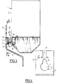
- the cutout 6 formed in the receiving member 5 has for example the shape of a pear and is formed by a first opening 7 of width greater than the head 11b of the screw 11 and by a second opening 8 opening into the first opening 7 and of width between the width of the rod 11a of the screw 11 and the width of the head 11b of said screw 11.
- the second opening 8 is arranged above the first opening 7 and in the axis of said first opening 7.
- the positioning device includes left-right or front-rear keying members for mounting the reel 1 on the receiving member 5 and means for holding the reel 1 on the receiving member 5 before its final fixing on said receiving member 5.
- the polarizing members and the holding means are formed by the same elements.
- the keying and holding bodies are formed by an opening 9, for example of oblong shape, formed in the receiving member 5 and by a relief element 14 for attachment arranged on the support structure 2 of the reel 1 and intended to cooperate with said opening 9.
- This relief element 14 for attachment is formed for example by a lug, a pin or a hook.
- the relief element 14 for attachment is constituted by a hook.
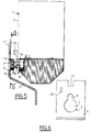
- the positioning device comprises left-right or front-rear keying members for mounting the reel 1 on the receiving member 5 and means for holding this reel 1 on the receiving member 5 before its final fixing on said receiving member 5 which are constituted by elements different from those constituting the polarizing members.
- the polarizing members are formed by an opening 15 for example of oblong shape formed in the receiving member 5 and by a raised element 16 disposed on the support structure 2 of the reel 1 and intended to cooperate with said opening 15.
- the holding means are formed by an opening 17 formed for example in the upper part of the receiving member 5 and by a relief element 18 for attachment arranged on the support structure 2 of the reel 1 and intended to cooperate with said opening 17.
- the relief element 16 is formed for example by a lug, a pin or a lug and the relief element 18 for attachment is formed for example by a hook or a T-shaped lug.
- the relief element 16 is formed by a pin and the relief element 18 for attachment is formed by a T-shaped tab.
- the opening 17 has the shape of a T in the plane of the receiving member 5.
- the positioning device comprises left-right or front-rear keying members for mounting the reel 1 on the receiving member 5 and means for holding this reel 1 on the receiving member 5 before its final fixing on said receiving member 5 which are constituted by elements different from those constituting the polarizing members.
- the polarizing members are formed by an opening 25 for example of oblong shape formed in the receiving member 5 and by a relief element 26 disposed on the support structure 2 of the reel 1 and intended to cooperate with said opening 15.
- the holding means are formed by an opening 27 formed for example at the upper part of the receiving member 5 and by a relief element 28 for hooking arranged on the support structure 2 of the reel 1 and intended to cooperate with said opening 27.
- the relief element 26 is formed for example by a lug, a pin or a lug and the relief element 28 for attachment is formed for example by a hook or a T-shaped lug.
- the relief element 26 is formed by a pin and the relief element 28 for attachment is formed by a T-shaped tab.
- the opening 27 is formed in this embodiment by a notch of determined height.
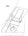
- the mounting of the reel 1 on the receiving member 3 is carried out as follows.
- the operator takes, the reel 1 whose support structure 2 is pre-equipped with the screw-nut assembly 10 and slides this reel 1 behind the receiving member 5 so as to introduce the head 11b of the screw 11 into the first opening 7 of the cutout 6 formed in the receiving member 5, as shown in FIG. 5.
- the reel 1 is therefore kept in its final place and the screw 11 can be tightened so as to permanently fix this reel 1 on the receiving member 5.
- the operator slides up the reel 1 so as to introduce the pin 16 into the opening 15 and it serves the screw 11 in order to permanently fix the reel 1 on the receiving member 5.
- the operator slides up the reel 1 so as to introduce the pin 26 into the opening 25 and passing the tab 28, in the shape of a T, above the upper edge of the receiving member 5.
- the positioning device therefore allows by simple means to position and maintain the reel on its receiving member before its final fixing and to fix this reel avoiding the operator tedious manipulations and in particular simultaneous manipulations the fixing screw and a screwdriver.
- the positioning device avoids degradation of the fastening members at the time of screwing by prepositioning the screw and the nut and prevents the operator from mounting a right element to the left, a front element. at the rear or vice versa, while allowing assembly to be carried out in a minimum time.
Landscapes
- Engineering & Computer Science (AREA)
- Mechanical Engineering (AREA)
- Automotive Seat Belt Assembly (AREA)
- Emergency Lowering Means (AREA)
Applications Claiming Priority (2)
| Application Number | Priority Date | Filing Date | Title |
|---|---|---|---|
| FR9605512 | 1996-05-02 | ||
| FR9605512A FR2748242B1 (fr) | 1996-05-02 | 1996-05-02 | Dispositif de positionnement d'un enrouleur de ceinture de securite dans un vehicule automobile |
Publications (2)
| Publication Number | Publication Date |
|---|---|
| EP0805076A1 true EP0805076A1 (de) | 1997-11-05 |
| EP0805076B1 EP0805076B1 (de) | 2001-11-28 |
Family
ID=9491777
Family Applications (1)
| Application Number | Title | Priority Date | Filing Date |
|---|---|---|---|
| EP19970400987 Expired - Lifetime EP0805076B1 (de) | 1996-05-02 | 1997-04-30 | Vorrichtung zum Positionieren eines Sicherheitsgurt-Aufrollers in einem Kraftfahrzeug |
Country Status (3)
| Country | Link |
|---|---|
| EP (1) | EP0805076B1 (de) |
| DE (1) | DE69708498T2 (de) |
| FR (1) | FR2748242B1 (de) |
Cited By (1)
| Publication number | Priority date | Publication date | Assignee | Title |
|---|---|---|---|---|
| EP0987448A1 (de) * | 1998-09-17 | 2000-03-22 | DaimlerChrysler AG | Anordnung zur Befestigung einer Baugruppe mit mindestens einer an dieser Baugruppe vormontierten Befestigungsschraube an einem Träger mit einer zugeordneten Öffnung |
Citations (3)
| Publication number | Priority date | Publication date | Assignee | Title |
|---|---|---|---|---|
| FR1536500A (fr) * | 1966-07-26 | 1968-08-16 | Reiche & Co | Système de jonction de tubes disposés perpendiculairement l'un par rapport à l'autre, en particulier de tubes profilés |
| DE3318740A1 (de) * | 1983-05-21 | 1984-11-29 | Adam Opel AG, 6090 Rüsselsheim | Kraftfahrzeug mit einem gurtaufroller fuer ein sicherheitsgurtsystem |
| DE3343104A1 (de) * | 1983-11-29 | 1985-06-05 | Autoliv GmbH, 2200 Elmshorn | Vorrichtung zum befestigen des gehaeuses einer automatischen aufrolleinrichtung fuer sicherheitsgurte und deren end- und umlenkbeschlaege |
-
1996
- 1996-05-02 FR FR9605512A patent/FR2748242B1/fr not_active Expired - Fee Related
-
1997
- 1997-04-30 DE DE1997608498 patent/DE69708498T2/de not_active Expired - Fee Related
- 1997-04-30 EP EP19970400987 patent/EP0805076B1/de not_active Expired - Lifetime
Patent Citations (3)
| Publication number | Priority date | Publication date | Assignee | Title |
|---|---|---|---|---|
| FR1536500A (fr) * | 1966-07-26 | 1968-08-16 | Reiche & Co | Système de jonction de tubes disposés perpendiculairement l'un par rapport à l'autre, en particulier de tubes profilés |
| DE3318740A1 (de) * | 1983-05-21 | 1984-11-29 | Adam Opel AG, 6090 Rüsselsheim | Kraftfahrzeug mit einem gurtaufroller fuer ein sicherheitsgurtsystem |
| DE3343104A1 (de) * | 1983-11-29 | 1985-06-05 | Autoliv GmbH, 2200 Elmshorn | Vorrichtung zum befestigen des gehaeuses einer automatischen aufrolleinrichtung fuer sicherheitsgurte und deren end- und umlenkbeschlaege |
Cited By (1)
| Publication number | Priority date | Publication date | Assignee | Title |
|---|---|---|---|---|
| EP0987448A1 (de) * | 1998-09-17 | 2000-03-22 | DaimlerChrysler AG | Anordnung zur Befestigung einer Baugruppe mit mindestens einer an dieser Baugruppe vormontierten Befestigungsschraube an einem Träger mit einer zugeordneten Öffnung |
Also Published As
| Publication number | Publication date |
|---|---|
| EP0805076B1 (de) | 2001-11-28 |
| FR2748242B1 (fr) | 1998-07-31 |
| DE69708498D1 (de) | 2002-01-10 |
| DE69708498T2 (de) | 2002-08-29 |
| FR2748242A1 (fr) | 1997-11-07 |
Similar Documents
| Publication | Publication Date | Title |
|---|---|---|
| EP1241072B1 (de) | Verbindung eines Lenksäulenbügels mit einem Kraftfahrzeuglenkungsritzel | |
| EP0260170B1 (de) | Auf einer festen Fahrzeugwand befestigter Bremskraftverstärker | |
| EP3927601B1 (de) | Befestigungseinrichtung eines schutzkomponentes unter motor | |
| EP3585656A1 (de) | Vorrichtung zur befestigung eines stossfängers an einem stossfängerträger eines kraftfahrzeug | |
| FR2792588A1 (fr) | Dispositif de montage d'un bloc optique sur des elements de carrosserie d'un vehicule automobile | |
| EP1517826B1 (de) | Strukturelement mit einer mutter zur befestigung an einem pfosten und entsprechendes kraftfahrzeug | |
| EP0805076B1 (de) | Vorrichtung zum Positionieren eines Sicherheitsgurt-Aufrollers in einem Kraftfahrzeug | |
| EP0371831A1 (de) | Montageeinrichtung für einen Servomotor auf einer Fahrzeugspritzwand | |
| EP1544032B1 (de) | Halterung für KFZ-Beleuchtungsanordnung, Beleuchtungsanordnung und Baugruppe mit einem Frontmodul und einer solchen Halterung bzw. Beleuchtungsanordnung | |
| EP2017408B1 (de) | Vorrichtung zur Vorpositionierung eines Schliessbügels, der mit dem Schloss eines Kraftfahrzeugsflügels zusammenwirken soll, und Kraftfahrzeug mit mindestens einer solchen Vorrichtung | |
| EP0497636B1 (de) | Befestigungseinrichtung einer Stossstange eines Fahrzeuges | |
| FR2929223A1 (fr) | Fixation d'une piece fonctionnelle a une partie de caisse de structure de vehicule. | |
| FR2921988A1 (fr) | Piece rapportee avec dispositif de fixation integre et procede de fixation d'une telle piece | |
| FR2821813A1 (fr) | Face avant technique de vehicule automobile comprenant un module de refroidissement | |
| EP1032510B1 (de) | Einstellbare montagevorrichtung für signal-oder beleuchtungseinrichtung und dazugehöriges strukturelement für kraftfahrzeuge | |
| EP0459849B1 (de) | Einstellbare Befestigungsvorrichtung für eine Fahrzeugstossstange | |
| EP0296961A1 (de) | Befestigungsvorrichtung | |
| FR2784955A1 (fr) | Dispositif de fixation d'un element exterieur de carrosserie sur une structure de vehicule, et vehicule comportant un tel dispositif | |
| EP0374032B1 (de) | Einrichtung und Verfahren insbesondere der automatischen Montage einer funktionellen oder Zierkonstruktion an eine äussere oder vordere Montagefläche einer Wandung eines Traggliedes | |
| FR3140331A1 (fr) | Obturateur pour garniture intérieure de véhicule automobile et véhicule automobile équipé d’un tel obturateur | |
| FR3076514A1 (fr) | Support de ferrure de boucle de ceinture de securite pour un vehicule automobile. | |
| EP1319532B1 (de) | Anordnung zur Befestigung an einem Hohlträger von einer Kupplungsvorrichtung an einem Schlepp- oder Verankerungsteil eines Kraftfahrzeuges | |
| EP1277617A2 (de) | Befestigungsvorrichtung für einen Kraftfahrzeugaussenrückblickspiegel | |
| FR3148957A1 (fr) | Calandre de véhicule automobile formant une jonction fusible avec une peau de pare-chocs en cas de choc frontal | |
| FR3159138A1 (fr) | Support de boitier à fusibles et procédé de fixation d’un tel support. |
Legal Events
| Date | Code | Title | Description |
|---|---|---|---|
| PUAI | Public reference made under article 153(3) epc to a published international application that has entered the european phase |
Free format text: ORIGINAL CODE: 0009012 |
|
| AK | Designated contracting states |
Kind code of ref document: A1 Designated state(s): DE ES GB IT PT |
|
| 17P | Request for examination filed |
Effective date: 19980425 |
|
| 17Q | First examination report despatched |
Effective date: 19990812 |
|
| GRAG | Despatch of communication of intention to grant |
Free format text: ORIGINAL CODE: EPIDOS AGRA |
|
| GRAG | Despatch of communication of intention to grant |
Free format text: ORIGINAL CODE: EPIDOS AGRA |
|
| GRAH | Despatch of communication of intention to grant a patent |
Free format text: ORIGINAL CODE: EPIDOS IGRA |
|
| GRAH | Despatch of communication of intention to grant a patent |
Free format text: ORIGINAL CODE: EPIDOS IGRA |
|
| GRAA | (expected) grant |
Free format text: ORIGINAL CODE: 0009210 |
|
| AK | Designated contracting states |
Kind code of ref document: B1 Designated state(s): DE ES GB IT PT |
|
| PG25 | Lapsed in a contracting state [announced via postgrant information from national office to epo] |
Ref country code: IT Free format text: LAPSE BECAUSE OF FAILURE TO SUBMIT A TRANSLATION OF THE DESCRIPTION OR TO PAY THE FEE WITHIN THE PRESCRIBED TIME-LIMIT;WARNING: LAPSES OF ITALIAN PATENTS WITH EFFECTIVE DATE BEFORE 2007 MAY HAVE OCCURRED AT ANY TIME BEFORE 2007. THE CORRECT EFFECTIVE DATE MAY BE DIFFERENT FROM THE ONE RECORDED. Effective date: 20011128 |
|
| REG | Reference to a national code |
Ref country code: GB Ref legal event code: IF02 |
|
| REF | Corresponds to: |
Ref document number: 69708498 Country of ref document: DE Date of ref document: 20020110 |
|
| GBT | Gb: translation of ep patent filed (gb section 77(6)(a)/1977) |
Effective date: 20020128 |
|
| PG25 | Lapsed in a contracting state [announced via postgrant information from national office to epo] |
Ref country code: PT Free format text: LAPSE BECAUSE OF FAILURE TO SUBMIT A TRANSLATION OF THE DESCRIPTION OR TO PAY THE FEE WITHIN THE PRESCRIBED TIME-LIMIT Effective date: 20020228 |
|
| PG25 | Lapsed in a contracting state [announced via postgrant information from national office to epo] |
Ref country code: ES Free format text: LAPSE BECAUSE OF FAILURE TO SUBMIT A TRANSLATION OF THE DESCRIPTION OR TO PAY THE FEE WITHIN THE PRESCRIBED TIME-LIMIT Effective date: 20020530 |
|
| PLBE | No opposition filed within time limit |
Free format text: ORIGINAL CODE: 0009261 |
|
| STAA | Information on the status of an ep patent application or granted ep patent |
Free format text: STATUS: NO OPPOSITION FILED WITHIN TIME LIMIT |
|
| 26N | No opposition filed | ||
| REG | Reference to a national code |
Ref country code: GB Ref legal event code: 746 Effective date: 20070117 |
|
| PGFP | Annual fee paid to national office [announced via postgrant information from national office to epo] |
Ref country code: GB Payment date: 20080326 Year of fee payment: 12 |
|
| PGFP | Annual fee paid to national office [announced via postgrant information from national office to epo] |
Ref country code: DE Payment date: 20090504 Year of fee payment: 13 |
|
| GBPC | Gb: european patent ceased through non-payment of renewal fee |
Effective date: 20090430 |
|
| PG25 | Lapsed in a contracting state [announced via postgrant information from national office to epo] |
Ref country code: GB Free format text: LAPSE BECAUSE OF NON-PAYMENT OF DUE FEES Effective date: 20090430 |
|
| PG25 | Lapsed in a contracting state [announced via postgrant information from national office to epo] |
Ref country code: DE Free format text: LAPSE BECAUSE OF NON-PAYMENT OF DUE FEES Effective date: 20101103 |