EP0805065A2 - Längsverstellvorrichtung für Kraftfahrzeugsitze - Google Patents
Längsverstellvorrichtung für Kraftfahrzeugsitze Download PDFInfo
- Publication number
- EP0805065A2 EP0805065A2 EP97104376A EP97104376A EP0805065A2 EP 0805065 A2 EP0805065 A2 EP 0805065A2 EP 97104376 A EP97104376 A EP 97104376A EP 97104376 A EP97104376 A EP 97104376A EP 0805065 A2 EP0805065 A2 EP 0805065A2
- Authority
- EP
- European Patent Office
- Prior art keywords
- locking bolt
- locking
- aligned
- spring
- opening
- Prior art date
- Legal status (The legal status is an assumption and is not a legal conclusion. Google has not performed a legal analysis and makes no representation as to the accuracy of the status listed.)
- Granted
Links
Images
Classifications
-
- B—PERFORMING OPERATIONS; TRANSPORTING
- B60—VEHICLES IN GENERAL
- B60N—SEATS SPECIALLY ADAPTED FOR VEHICLES; VEHICLE PASSENGER ACCOMMODATION NOT OTHERWISE PROVIDED FOR
- B60N2/00—Seats specially adapted for vehicles; Arrangement or mounting of seats in vehicles
- B60N2/02—Seats specially adapted for vehicles; Arrangement or mounting of seats in vehicles the seat or part thereof being movable, e.g. adjustable
- B60N2/04—Seats specially adapted for vehicles; Arrangement or mounting of seats in vehicles the seat or part thereof being movable, e.g. adjustable the whole seat being movable
- B60N2/06—Seats specially adapted for vehicles; Arrangement or mounting of seats in vehicles the seat or part thereof being movable, e.g. adjustable the whole seat being movable slidable
- B60N2/08—Seats specially adapted for vehicles; Arrangement or mounting of seats in vehicles the seat or part thereof being movable, e.g. adjustable the whole seat being movable slidable characterised by the locking device
- B60N2/0831—Movement of the latch
- B60N2/0862—Movement of the latch sliding
- B60N2/0868—Movement of the latch sliding in a transversal direction
-
- B—PERFORMING OPERATIONS; TRANSPORTING
- B60—VEHICLES IN GENERAL
- B60N—SEATS SPECIALLY ADAPTED FOR VEHICLES; VEHICLE PASSENGER ACCOMMODATION NOT OTHERWISE PROVIDED FOR
- B60N2/00—Seats specially adapted for vehicles; Arrangement or mounting of seats in vehicles
- B60N2/02—Seats specially adapted for vehicles; Arrangement or mounting of seats in vehicles the seat or part thereof being movable, e.g. adjustable
- B60N2/04—Seats specially adapted for vehicles; Arrangement or mounting of seats in vehicles the seat or part thereof being movable, e.g. adjustable the whole seat being movable
- B60N2/06—Seats specially adapted for vehicles; Arrangement or mounting of seats in vehicles the seat or part thereof being movable, e.g. adjustable the whole seat being movable slidable
- B60N2/07—Slide construction
- B60N2/0702—Slide construction characterised by its cross-section
- B60N2/0705—Slide construction characterised by its cross-section omega-shaped
-
- B—PERFORMING OPERATIONS; TRANSPORTING
- B60—VEHICLES IN GENERAL
- B60N—SEATS SPECIALLY ADAPTED FOR VEHICLES; VEHICLE PASSENGER ACCOMMODATION NOT OTHERWISE PROVIDED FOR
- B60N2/00—Seats specially adapted for vehicles; Arrangement or mounting of seats in vehicles
- B60N2/02—Seats specially adapted for vehicles; Arrangement or mounting of seats in vehicles the seat or part thereof being movable, e.g. adjustable
- B60N2/04—Seats specially adapted for vehicles; Arrangement or mounting of seats in vehicles the seat or part thereof being movable, e.g. adjustable the whole seat being movable
- B60N2/06—Seats specially adapted for vehicles; Arrangement or mounting of seats in vehicles the seat or part thereof being movable, e.g. adjustable the whole seat being movable slidable
- B60N2/07—Slide construction
- B60N2/0702—Slide construction characterised by its cross-section
- B60N2/0715—C or U-shaped
-
- B—PERFORMING OPERATIONS; TRANSPORTING
- B60—VEHICLES IN GENERAL
- B60N—SEATS SPECIALLY ADAPTED FOR VEHICLES; VEHICLE PASSENGER ACCOMMODATION NOT OTHERWISE PROVIDED FOR
- B60N2/00—Seats specially adapted for vehicles; Arrangement or mounting of seats in vehicles
- B60N2/02—Seats specially adapted for vehicles; Arrangement or mounting of seats in vehicles the seat or part thereof being movable, e.g. adjustable
- B60N2/04—Seats specially adapted for vehicles; Arrangement or mounting of seats in vehicles the seat or part thereof being movable, e.g. adjustable the whole seat being movable
- B60N2/06—Seats specially adapted for vehicles; Arrangement or mounting of seats in vehicles the seat or part thereof being movable, e.g. adjustable the whole seat being movable slidable
- B60N2/08—Seats specially adapted for vehicles; Arrangement or mounting of seats in vehicles the seat or part thereof being movable, e.g. adjustable the whole seat being movable slidable characterised by the locking device
- B60N2/0812—Location of the latch
- B60N2/0818—Location of the latch inside the rail
-
- B—PERFORMING OPERATIONS; TRANSPORTING
- B60—VEHICLES IN GENERAL
- B60N—SEATS SPECIALLY ADAPTED FOR VEHICLES; VEHICLE PASSENGER ACCOMMODATION NOT OTHERWISE PROVIDED FOR
- B60N2/00—Seats specially adapted for vehicles; Arrangement or mounting of seats in vehicles
- B60N2/02—Seats specially adapted for vehicles; Arrangement or mounting of seats in vehicles the seat or part thereof being movable, e.g. adjustable
- B60N2/04—Seats specially adapted for vehicles; Arrangement or mounting of seats in vehicles the seat or part thereof being movable, e.g. adjustable the whole seat being movable
- B60N2/06—Seats specially adapted for vehicles; Arrangement or mounting of seats in vehicles the seat or part thereof being movable, e.g. adjustable the whole seat being movable slidable
- B60N2/08—Seats specially adapted for vehicles; Arrangement or mounting of seats in vehicles the seat or part thereof being movable, e.g. adjustable the whole seat being movable slidable characterised by the locking device
- B60N2/0812—Location of the latch
- B60N2/0825—Location of the latch outside the rail
Definitions
- the invention relates to a longitudinal adjustment device for motor vehicle seats according to the preamble of claim 1.
- Such longitudinal adjustment devices are used, inter alia, in motor vehicles which have two pairs of lateral slide rails and a central front pair of slide rails which has a top rail connected to the seat, which runs on fixed castors and is guided or held in a fixed fixed lower rail.
- the invention has for its object to provide a longitudinal adjustment device of the type presumed to be known so that it is evenly loaded in the event of a crash and enables secure locking without requiring particularly large profile thicknesses.
- the longitudinal adjustment device allows a uniform removal of the load from the seat on the chassis.
- the upper rail 2 is guided in an approximately C-shaped lower rail.
- Sliding bodies 11 and 12 are seated on the legs 1a and 1b of the lower rail 1, which are bent downwards.
- the two sliding bodies 11 and 12 engage in the grooves 2f and 2g of the upper rail.
- the lower rail 1 is fastened to the vehicle floor via fastening flanges 1c.
- parallel flanges 1e and 1d are welded parallel to one another and extending in the longitudinal direction of the vehicle. Between the two flanges 1e and 1d there is a transverse spacer 4 with a recess 4a.
- a sleeve 13 extending transversely to the longitudinal direction, in which a first locking bolt 6a is mounted so as to be transversely displaceable.
- the first locking bolt 6a passes through a through opening 2a in the side leg 2e of the top rail 2.
- the through opening 2a is shown in FIG Embodiment provided in a reinforcing rail 10 made of metal.
- a sleeve 8 Aligned with the sleeve 13 is a sleeve 8 which is fastened between the vertically extending flanges 1e and 1d.
- a second locking bolt 6b is flush aligned with the first locking bolt 6a.
- the second locking bolt 6b engages with its front through a through opening 2b in the side leg 2d of the top rail 2.
- the second locking pin 6b is under the action of a return spring 9 designed as a compression spring.
- This return spring 9 is supported on the one hand on an inner collar of the sleeve 8 and on the other hand on a circumferential collar of the second locking pin 6b.
- the first locking bolt 6a is under the action of a tension spring 5.
- the spring force of the tension spring 5 is greater than the spring force of the return spring 9, which is designed as a compression spring. This has the consequence that the locking bolt 6a has the second locking bolt 6b in at suitably opposite through openings 2a and 2d presses the locking position shown in Figure 1.
- the first locking bolt 6a is pulled to the left via a pulling hook 7, overcoming the force of the tension spring 5 according to FIG. 2, until the front end of the locking bolt 6a has emerged from the through opening 2a.
- the second locking bolt 6b becomes a left one under the action of the compression spring 9 Stop moved, the front and in the drawings right end of the second locking pin 6b is swung out of the recess 2b. In this unlocked position, the seat can be moved lengthways.
- the multiple rollers 3 run on the inside of the base leg 2c of the substantially U-shaped top rail 2.
Landscapes
- Engineering & Computer Science (AREA)
- Aviation & Aerospace Engineering (AREA)
- Transportation (AREA)
- Mechanical Engineering (AREA)
- Seats For Vehicles (AREA)
Abstract
Description
- Die Erfindung betrifft eine Längsverstellvorrichtung für Kraftfahrzeugsitze nach dem Oberbegriff des Anspruchs 1.
- Derartige Längsverstellvorrichtungen werden unter anderem bei Kraftfahrzeugen verwendet, welche zwei seitliche Gleitschienenpaare aufweisen und ein zentrales vorderes Gleitschienenpaar, das eine mit dem Sitz verbundene Oberschiene aufweist, die auf chassisfesten Rollen abläuft und in einer chassisfesten Unterschiene geführt bzw. gehalten wird.
- Als nachteilig erweist es sich bei derartigen Längsverstellvorrichtungen, daß die Oberschienen im Crashfall einseitig belastet werden und möglicherweise ausreißen können.
- Ausgehend von diesem Stand der Technik liegt der Erfindung die Aufgabe zugrunde, eine Längsverstellvorrichtung der als bekannt vorausgesetzten Art so auszubilden, daß sie im Crashfall gleichmäßig belastet wird und eine sichere Verriegelung ermöglicht, ohne daß hierzu besonders große Profilstärken erforderlich sind.
- Die Lösung dieser Aufgabe erfolgt mit den Merkmalen des Kennzeichnungsteils von Anspruch 1.
- Bevorzugte Ausgestaltungen der Erfindung sind in den Unteransprüchen beschrieben.
- Die erfindungsgemäße Längsverstellvorrichtung erlaubt ein gleichmäßiges Abtragen der Last vom Sitz auf das Chassis.
- Nachstehend wird eine bevorzugte Ausführungsform der Erfindung anhand der Zeichnung im einzelnen beschrieben. Es zeigen:
- Figur 1 -
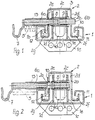
- einen Querschnitt durch die Längsverstellvorrichtung im verriegelten Zustand,
- Figur 2 -
- den Querschnitt gemäß Figur 1 im entriegelten Zustand.
- Eine mit einem nicht dargestellten Kraftfahrzeugsitz verbundene, im wesentlichen U-förmige Oberschiene 2 läuft auf mehreren chassisfest gelagerten Laufrollen 3 ab. Die Oberschiene 2 wird in einer etwa C-förmigen Unterschiene geführt. Auf den nach unten gekröpften Schenkeln 1a und 1b der Unterschiene 1 sitzen Gleitkörper 11 und 12. Die beiden Gleitkörper 11 und 12 greifen in die Rinnen 2f und 2g der Oberschiene ein. Die Unterschiene 1 ist über Befestigungsflansche 1c am Fahrzeugboden befestigt. An die nach oben weisende Innenseite des horizontalen Basisschenkels der Unterschiene 1 sind zueinander parallel und in Fahrzeuglängsrichtung verlaufende senkrechte Flansch 1e und 1d angeschweißt. Zwischen den beiden Flanschen 1e und 1d befindet sich ein quer verlaufendes Distanzblech 4 mit einer Aussparung 4a.
- An der Unterschiene 1 ist seitlich eine quer zur Längsrichtung verlaufene Hülse 13 angeschweißt, in der ein erster Verriegelungsbolzen 6a quer verschieblich gelagert ist. Der erste Verriegelungsbolzen 6a durchgreift in Verriegelungsstellung eine Durchgangsöffnung 2a im Seitenschenkel 2e der Oberschiene 2. Die Durchgangsöffnung 2a ist im dargestellten Ausführungsbeispiel in einer Verstärkungsschiene 10 aus Metall vorgesehen.
- Mit der Hülse 13 fluchtet eine Hülse 8, die zwischen den vertikal sich erstreckenden Flanschen 1e und 1d befestigt ist. In der Hülse 8 ist ein zweiter Verriegelungsbolzen 6b fluchtend mit dem ersten Verriegelungsbolzen 6a quer verschieblich gelagert. Der zweite Verriegelungsbolzen 6b greift im verriegelten Zustand gemäß Figur 1 mit seiner Frontseite durch eine Durchgangsöffnung 2b im Seitenschenkel 2d der Oberschiene 2.
- Der zweite Verriegelungsbolzen 6b steht unter der Wirkung einer als Druckfeder ausgebildeten Rückstellfeder 9. Diese Rückstellfeder 9 stützt sich einerseits an einem inneren Kragen der Hülse 8 ab und andererseits an einem umlaufenden Bund des zweiten Verriegelungsbolzens 6b.
- Der erste Verriegelungsbolzen 6a steht unter der Wirkung einer Zugfeder 5. Die Federkraft der Zugfeder 5 ist größer als die Federkraft der als Druckfeder ausgebildeten Rückstellfeder 9. Dies hat zur Folge, daß der Verriegelungsbolzen 6a bei passend gegenüberliegenden Durchgangsöffnungen 2a und 2d den zweiten Verriegelungsbolzen 6b in die in Figur 1 dargestellte Verriegelungsposition drückt.
- Zum Entriegeln wird der erste Verriegelungsbolzen 6a über eine Zughaken 7 unter Überwindung der Kraft der Zugfeder 5 gemäß Figur 2 nach links gezogen, bis das vordere Ende des Verriegelungsbolzens 6a aus der Durchgangsöffnung 2a ausgetaucht ist. Gleichzeitig wird der zweite Verriegelungsbolzen 6b unter der Wirkung der Druckfeder 9 bis zu einem linken Anschlag verschoben, wobei das vordere und in den Zeichnungen rechte Ende des zweiten Verriegelungsbolzens 6b aus der Ausnehmung 2b ausgetaucht ist. In dieser entriegelten Lage kann der Sitz in Längsrichtung verschoben werden.
- Die mehrfach vorgesehenen Laufrollen 3 laufen auf der Innenseite des Basisschenkels 2c der im wesentlichen U-förmigen Oberschiene 2 ab.
Claims (3)
- Längsverstellvorrichtung für Kraftfahrzeugsitze mit einer sitzfesten, in einer chassisfesten Unterschiene (1) geführten Oberschiene (2), die ein U-förmiges Grundprofil aufweist und entlang eines Seitenschenkels (2e) gleichmäßig über die Länge verteilt angeordnete Durchgangsöffnungen (2a) aufweist, die zur Aufnahme eines chassisfest quer zur Längsrichtung verschieblich geführten Verriegelungsbolzens ausgebildet sind, welcher unter Federvorspannung in die Verriegelungsstellung und gegen Federvorspannung in die Freigabestellung verschieblich ist,
dadurch gekennzeichnet,
daß entlang des zweiten Seitenschenkels (2d) mit den Durchgangsöffnungen des ersten Seitenschenkels (2e) fluchtende, zweite Durchgangsöffnungen (2b) vorgesehen sind, die zum Eingriff eines chassisfest quer zur Längsrichtung verschieblich geführten zweiten Verriegelungsbolzens (6b) ausgebildet sind, wobei der zweite Verriegelungsbolzen (6b) mit dem ersten Verriegelungsbolzen (6a) fluchtet und wobei der erste Verriegelungsbolzen (6a) zum Verriegeln auf der Rückseite des zweiten Verriegelungsbolzens (6b) anliegt und mittels der Federvorspannung den zweiten Verriegelungsbolzen (6b) unter Überwindung der Rückstellkraft von dessen Rückstellfeder (9) in die zweite Durchgangsöffnung (2b) verschiebt, wobei der zweite Verriegelungsbolzen (6b) unter der Kraft seiner Rückstellfeder (9) aus seiner gegenüberliegenden Durchgangsöffnung austaucht, sobald der erste Verriegelungsbolzen den zweiten Verriegelungsbolzen (6b) freigibt. - Längsverstellvorrichtung nach Anspruch 1,
dadurch gekennzeichnet,
daß der erste Verriegelungsbolzen (6a) unter der Vorspannung einer Zugfeder (5) steht. - Längsverstellvorrichtung nach Anspruch 1 oder 2,
dadurch gekennzeichnet,
daß der zweite Verriegelungsbolzen (6b) in einer ihn umgebenden Hülse (8) geführt ist und seine Rückstellfeder (9) einerseits innen an einem Kragen der Hülse (8) und andererseits an einem Bund des zweiten Verriegelungsbolzens (6b) anliegt.
Applications Claiming Priority (2)
| Application Number | Priority Date | Filing Date | Title |
|---|---|---|---|
| DE19617691A DE19617691C1 (de) | 1996-05-03 | 1996-05-03 | Längsverstellvorrichtung für Kraftfahrzeugsitze |
| DE19617691 | 1996-05-03 |
Publications (3)
| Publication Number | Publication Date |
|---|---|
| EP0805065A2 true EP0805065A2 (de) | 1997-11-05 |
| EP0805065A3 EP0805065A3 (de) | 1998-12-30 |
| EP0805065B1 EP0805065B1 (de) | 2001-05-23 |
Family
ID=7793171
Family Applications (1)
| Application Number | Title | Priority Date | Filing Date |
|---|---|---|---|
| EP97104376A Expired - Lifetime EP0805065B1 (de) | 1996-05-03 | 1997-03-14 | Längsverstellvorrichtung für Kraftfahrzeugsitze |
Country Status (2)
| Country | Link |
|---|---|
| EP (1) | EP0805065B1 (de) |
| DE (2) | DE19617691C1 (de) |
Cited By (1)
| Publication number | Priority date | Publication date | Assignee | Title |
|---|---|---|---|---|
| CN103079877A (zh) * | 2010-10-21 | 2013-05-01 | 凯波有限责任两合公司 | 适于车辆座椅的纵向调节器 |
Families Citing this family (8)
| Publication number | Priority date | Publication date | Assignee | Title |
|---|---|---|---|---|
| DE29700866U1 (de) * | 1997-01-20 | 1997-03-20 | Burger Söhne GmbH + Co, 71065 Sindelfingen | Verriegelungsvorrichtung für einen Fahrzeugsitz |
| DE19957201A1 (de) * | 1999-11-27 | 2001-06-07 | Giok Djien Go | Längsverstellmechanismus mit Hilfsmitteln zur Minimierung der Sitzbauteile, Montagezeit, Herstellungskosten und Beanspruchung |
| JP4542254B2 (ja) * | 2000-11-21 | 2010-09-08 | アイシン精機株式会社 | 車両用シートスライド装置 |
| DE10152208A1 (de) * | 2001-10-23 | 2003-05-08 | Keiper Gmbh & Co | Verriegelungsvorrichtung für einen Fahrzeugsitz |
| DE20313952U1 (de) * | 2003-09-05 | 2005-01-05 | Brose Fahrzeugteile Gmbh & Co. Kg, Coburg | Arretiereinrichtung einer Längsverstellvorrichtung eines Kraftfahrzeugsitzes |
| DE102007042595B4 (de) * | 2007-09-07 | 2015-06-25 | Johnson Controls Gmbh | Verstelleinrichtung zur Längsverstellung einer Kraftfahrzeugkomponente |
| JP6264075B2 (ja) * | 2013-07-30 | 2018-01-24 | アイシン精機株式会社 | 車両用シートスライド装置 |
| DE102020207924B3 (de) | 2020-06-25 | 2021-07-29 | Brose Fahrzeugteile SE & Co. Kommanditgesellschaft, Coburg | Verriegelungsvorrichtung für einen Fahrzeugsitz mit einem ein Verriegelungselement in einer Verriegelungsposition formschlüssig sichernden Sicherungsabschnitt, Verriegelungsbaugruppe und Fahrzeugsitz mit einer derartigen Verriegelungsvorrichtung |
Family Cites Families (4)
| Publication number | Priority date | Publication date | Assignee | Title |
|---|---|---|---|---|
| FR2213662A5 (de) * | 1972-12-27 | 1974-08-02 | Nissan Motor | |
| JPS57194121A (en) * | 1981-05-22 | 1982-11-29 | Oi Seisakusho Co Ltd | Seat slide of automobile |
| JPH0431184Y2 (de) * | 1985-05-17 | 1992-07-27 | ||
| US5447352A (en) * | 1992-06-22 | 1995-09-05 | Aisin Seiki Kabushiki Kaisha | Seat slide mechanism for vehicles |
-
1996
- 1996-05-03 DE DE19617691A patent/DE19617691C1/de not_active Expired - Fee Related
-
1997
- 1997-03-14 DE DE59703579T patent/DE59703579D1/de not_active Expired - Lifetime
- 1997-03-14 EP EP97104376A patent/EP0805065B1/de not_active Expired - Lifetime
Cited By (3)
| Publication number | Priority date | Publication date | Assignee | Title |
|---|---|---|---|---|
| CN103079877A (zh) * | 2010-10-21 | 2013-05-01 | 凯波有限责任两合公司 | 适于车辆座椅的纵向调节器 |
| US9162589B2 (en) | 2010-10-21 | 2015-10-20 | Keiper Gmbh & Co. Kg | Longitudinal adjustor for a vehicle seat |
| CN103079877B (zh) * | 2010-10-21 | 2015-12-09 | 凯波有限责任两合公司 | 适于车辆座椅的纵向调节器 |
Also Published As
| Publication number | Publication date |
|---|---|
| EP0805065B1 (de) | 2001-05-23 |
| EP0805065A3 (de) | 1998-12-30 |
| DE19617691C1 (de) | 1997-05-07 |
| DE59703579D1 (de) | 2001-06-28 |
Similar Documents
| Publication | Publication Date | Title |
|---|---|---|
| DE4314538C2 (de) | Überrollschutz-Vorrichtung für ein Kraftfahrzeug | |
| DE3726711C2 (de) | ||
| EP0993392A1 (de) | Vorrichtung zur schnellösbaren, verschiebbaren und schnell arretierbaren befestigung eines fahrzeugsausrüstungsteiles | |
| WO2009021497A1 (de) | Befestigungsbeschlag | |
| DE102015117709A1 (de) | Adapterschienensystem und Verfahren zum Befestigen eines Objekts an einer Fußbodenschiene in einem Transportmittel | |
| DE102021202560A1 (de) | Hebel für einen Fahrzeugsitz | |
| DE69205625T2 (de) | Sitzgleitvorrichtung. | |
| DE19626025A1 (de) | Sitzverschiebemechanismus | |
| EP0805065B1 (de) | Längsverstellvorrichtung für Kraftfahrzeugsitze | |
| DE2426728A1 (de) | Vorrichtung zum arretieren einer hoehenverstellbaren kopfstuetze | |
| DE10235086B4 (de) | Sicherheitseinrichtung für Fahrzeugsitze | |
| EP4308411B1 (de) | Verstelleinrichtung zur längsverstellung eines fahrzeugsitzes sowie zusatzverriegelung für selbige | |
| EP0729867A1 (de) | Überrollschutz-Vorrichtung für ein Kraftfahrzeug | |
| DE10040593A1 (de) | Verriegelungseinrichtung für längsverstellbare Sitze, insbesondere Kraftfahrzeugsitze | |
| EP3974281B1 (de) | Zustiegeinrichtung für ein fahrzeug | |
| DE102006028664B4 (de) | Überrollschutzsystem für ein Kraftfahrzeug | |
| DE10206780A1 (de) | Befestigungsvorrichtung für einen Kindersitz | |
| EP0623492B1 (de) | Überrollschutz-Vorrichtung für ein Kraftfahrzeug | |
| DE102013002948A1 (de) | Gurtschlossbringer | |
| DE69814570T2 (de) | Anordnung für einen ausnehmbaren und in Längsrichtung verstellbaren Sitz im Innenraum eines Kraftfahrzeuges | |
| EP0900689A1 (de) | Abstützung eines Fahrzeugsitzes, insbesondere einer längsverstellbaren hinteren Sitzbank | |
| DE202018104929U1 (de) | Sicherungskeil | |
| DE4432861A1 (de) | Verriegelungsvorrichtung für Fahrzeugsitze | |
| EP1122121A2 (de) | Transportbehälter-Einrichtung für den Einbau in Kraftfahrzeuge, wie z.B. Durchladeeinrichtung | |
| DE29908320U1 (de) | Höhenverstellvorrichtung für Gurtbeschlag |
Legal Events
| Date | Code | Title | Description |
|---|---|---|---|
| PUAI | Public reference made under article 153(3) epc to a published international application that has entered the european phase |
Free format text: ORIGINAL CODE: 0009012 |
|
| AK | Designated contracting states |
Kind code of ref document: A2 Designated state(s): DE FR GB IT |
|
| PUAL | Search report despatched |
Free format text: ORIGINAL CODE: 0009013 |
|
| AK | Designated contracting states |
Kind code of ref document: A3 Designated state(s): DE FR GB IT |
|
| 17P | Request for examination filed |
Effective date: 19981118 |
|
| GRAG | Despatch of communication of intention to grant |
Free format text: ORIGINAL CODE: EPIDOS AGRA |
|
| 17Q | First examination report despatched |
Effective date: 20000920 |
|
| GRAG | Despatch of communication of intention to grant |
Free format text: ORIGINAL CODE: EPIDOS AGRA |
|
| GRAH | Despatch of communication of intention to grant a patent |
Free format text: ORIGINAL CODE: EPIDOS IGRA |
|
| GRAH | Despatch of communication of intention to grant a patent |
Free format text: ORIGINAL CODE: EPIDOS IGRA |
|
| ITF | It: translation for a ep patent filed | ||
| RAP1 | Party data changed (applicant data changed or rights of an application transferred) |
Owner name: PROGRESS-WERK OBERKIRCH AKTIENGESELLSCHAFT Owner name: FAURECIA AUTOSITZE GMBH & CO. KG |
|
| GRAA | (expected) grant |
Free format text: ORIGINAL CODE: 0009210 |
|
| AK | Designated contracting states |
Kind code of ref document: B1 Designated state(s): DE FR GB IT |
|
| GBT | Gb: translation of ep patent filed (gb section 77(6)(a)/1977) |
Effective date: 20010523 |
|
| REF | Corresponds to: |
Ref document number: 59703579 Country of ref document: DE Date of ref document: 20010628 |
|
| ET | Fr: translation filed | ||
| REG | Reference to a national code |
Ref country code: GB Ref legal event code: IF02 |
|
| PLBE | No opposition filed within time limit |
Free format text: ORIGINAL CODE: 0009261 |
|
| STAA | Information on the status of an ep patent application or granted ep patent |
Free format text: STATUS: NO OPPOSITION FILED WITHIN TIME LIMIT |
|
| 26N | No opposition filed | ||
| PGFP | Annual fee paid to national office [announced via postgrant information from national office to epo] |
Ref country code: GB Payment date: 20090311 Year of fee payment: 13 |
|
| PGFP | Annual fee paid to national office [announced via postgrant information from national office to epo] |
Ref country code: IT Payment date: 20090327 Year of fee payment: 13 |
|
| PGFP | Annual fee paid to national office [announced via postgrant information from national office to epo] |
Ref country code: FR Payment date: 20090313 Year of fee payment: 13 |
|
| PGFP | Annual fee paid to national office [announced via postgrant information from national office to epo] |
Ref country code: DE Payment date: 20100223 Year of fee payment: 14 |
|
| GBPC | Gb: european patent ceased through non-payment of renewal fee |
Effective date: 20100314 |
|
| REG | Reference to a national code |
Ref country code: FR Ref legal event code: ST Effective date: 20101130 |
|
| PG25 | Lapsed in a contracting state [announced via postgrant information from national office to epo] |
Ref country code: FR Free format text: LAPSE BECAUSE OF NON-PAYMENT OF DUE FEES Effective date: 20100331 |
|
| PG25 | Lapsed in a contracting state [announced via postgrant information from national office to epo] |
Ref country code: GB Free format text: LAPSE BECAUSE OF NON-PAYMENT OF DUE FEES Effective date: 20100314 Ref country code: IT Free format text: LAPSE BECAUSE OF NON-PAYMENT OF DUE FEES Effective date: 20100314 |
|
| PG25 | Lapsed in a contracting state [announced via postgrant information from national office to epo] |
Ref country code: DE Free format text: LAPSE BECAUSE OF NON-PAYMENT OF DUE FEES Effective date: 20111001 |
|
| REG | Reference to a national code |
Ref country code: DE Ref legal event code: R119 Ref document number: 59703579 Country of ref document: DE Effective date: 20111001 |