EP0804968B1 - Vorrichtung zur Erzeugung eines einstellbaren Flüssigkeits-strahls - Google Patents
Vorrichtung zur Erzeugung eines einstellbaren Flüssigkeits-strahls Download PDFInfo
- Publication number
- EP0804968B1 EP0804968B1 EP97106508A EP97106508A EP0804968B1 EP 0804968 B1 EP0804968 B1 EP 0804968B1 EP 97106508 A EP97106508 A EP 97106508A EP 97106508 A EP97106508 A EP 97106508A EP 0804968 B1 EP0804968 B1 EP 0804968B1
- Authority
- EP
- European Patent Office
- Prior art keywords
- nozzle
- nozzle tube
- plunger
- elastic element
- actuating piston
- Prior art date
- Legal status (The legal status is an assumption and is not a legal conclusion. Google has not performed a legal analysis and makes no representation as to the accuracy of the status listed.)
- Expired - Lifetime
Links
- 239000012530 fluid Substances 0.000 title claims description 3
- 239000007788 liquid Substances 0.000 claims description 11
- 238000007789 sealing Methods 0.000 claims description 9
- 239000003292 glue Substances 0.000 claims description 3
- 239000000758 substrate Substances 0.000 claims description 2
- 230000000052 comparative effect Effects 0.000 description 2
- 238000012423 maintenance Methods 0.000 description 1
- 238000004519 manufacturing process Methods 0.000 description 1
- 210000000056 organ Anatomy 0.000 description 1
- 238000009423 ventilation Methods 0.000 description 1
Images
Classifications
-
- B—PERFORMING OPERATIONS; TRANSPORTING
- B05—SPRAYING OR ATOMISING IN GENERAL; APPLYING FLUENT MATERIALS TO SURFACES, IN GENERAL
- B05B—SPRAYING APPARATUS; ATOMISING APPARATUS; NOZZLES
- B05B1/00—Nozzles, spray heads or other outlets, with or without auxiliary devices such as valves, heating means
- B05B1/30—Nozzles, spray heads or other outlets, with or without auxiliary devices such as valves, heating means designed to control volume of flow, e.g. with adjustable passages
- B05B1/32—Nozzles, spray heads or other outlets, with or without auxiliary devices such as valves, heating means designed to control volume of flow, e.g. with adjustable passages in which a valve member forms part of the outlet opening
Definitions
- the invention relates to a device for generating a adjustable liquid jet, especially when applying Glue and / or soft liquid on a web, with a nozzle head, one with one at the end one with the one to be processed Arranged liquid flow path Opening provided nozzle, being in the area of the opening elastic element is provided, the one with the Has flow path communicating passage recess and that between two by means of one on the nozzle holder provided adjusting device adjustable relative to each other Press organs inform one of the front, the elastic element receiving nozzle tube and an engaging, pierced pressure bolt is arranged.
- a at least one with the passage recess of the elastic Elements communicating, through hole provided Piston arrangement is provided, which in the nozzle tube, the Nozzle head is rigidly attached, engaging pressure bolts, one adjoining this, on the side facing away from the pressure pin Side a pressure chamber to which a pressure medium can be applied limiting actuating piston and one of them on the Push pin protruding from the opposite side, one has a smaller diameter sealing pin, the sealing in one going from the pressure room, with the processing fluid pressurized bore intervenes.
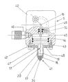
- the drawing shows a nozzle head according to the invention partially on average.
- the nozzle head 5 shown consists of a housing block 40, to which a nozzle 41 is flanged. This has one on her front end conically narrowed, a front opening 34 having nozzle tube 19 which is connected to a rear flange 42nd is formed, which is fastened to the housing block 40 by screws is.
- a Housing block 40 provided cylinder space 43. This owns a larger diameter than the bore of the nozzle tube 19 and is closed outside of this by the flange 42.
- elastic element 18 is provided, which is a central Passage recess 17 which is in the region of the front Opening 34 of the nozzle tube 19 opens out and with a feed line 16 for in the form of a beam onto a substrate, for example a moving paper web, liquid that can be applied, for example glue or soft liquid.
- a substrate for example a moving paper web
- liquid that can be applied for example glue or soft liquid.
- the nozzle tube 19 which is rigidly arranged is inserted and supported by this elastic element 18 by an in the nozzle tube 19 engaging pressure pin 20 more or less strongly pressed against the associated support surface of the nozzle tube 19.
- the pressure pin 20 is in the housing block 40 arranged actuating device actuated.
- an adjusting piston 44 is arranged in the cylinder space 43 provided, of which the one with a smaller diameter Push pin 20 protrudes downwards and on the Push pin 20 opposite side a pressure chamber 45 limited by a supply connection 46 with a Pressure medium, for example compressed air, can be acted upon.
- the pressure of the pressure medium can be used to regulate the crushing of the elastic element 18 to be adjustable.
- the maximal Actuating movement of the actuating piston 44 is by a stop limited.
- the flange 42 can be threaded be provided in which an adjusting screw 47 is received, the forms an adjustable stop.
- the flange 42 can also with be provided with a ventilation recess 48.
- a blind bore 49 goes upwards, into which the feed line 16 opens for the liquid to be processed.
- an attached to the actuating piston 44 engages the sealing pin 50 opposite the pressure pin 20. This is opposite the wall of the blind bore 49 by means of O-rings sealed.
- the actuating piston 44 is also opposed by O-rings sealed the wall of the associated cylinder space 43.
- the actuating piston 44 and the pressure bolt 20 and Sealing pin 50 form a piston arrangement in the form of a Stepped piston.
- This entire piston assembly is one central through hole 51 to which the Through recess 17 of the elastic element 18 connects, whereby the through recess 17 of the elastic Element 18 is connected to the feed line 16.
- the depth of engagement of the sealing pin 50 in the blind bore 49 is larger than that maximum travel of the actuating piston 44, so that the sealing pin 50th in any case remains in engagement with the blind bore 49, whereby the pressure chamber 45 reliably with respect to the feed line 16 for the liquid to be processed remains sealed. This will regardless of the position of the actuating piston 44 via the central Through recess 51 of the central through recess 17 of the elastic element 18 supplied.
Landscapes
- Coating Apparatus (AREA)
- Nozzles (AREA)
Description
Claims (4)
- Vorrichtung zur Erzeugung eines einstellbaren Flüssigkeitsstrahls, insbesondere beim Auftragen von Leim und/oder Soft-Flüssigkeit auf ein Substrat, mit einem Düsenkopf (5), der eine mit einer am Ende eines mit der zu verarbeitenden Flüssigkeit beaufschlagbaren Strömungswegs angeordneten Öffnung (34) versehene Düse (41) trägt, wobei im Bereich der Öffnung (34) ein elastisches Element (18) vorgesehen ist, das eine mit dem Strömungsweg verbundene Durchgangsausnehmung (17) aufweist und das zwischen zwei mittels einer auf dem Düsenkopf (5) vorgesehenen Stelleinrichtung relativ zueinander verstellbaren Preßorganen inform eines vorne verengten, das elastische Element (18) aufnehmenden Düsenrohrs (19) und eines in diese eingreifenden, durchbohrten Druckbolzens (20) angeordnet ist, dadurch gekennzeichnet, daß eine mit wenigstens einer mit der Durchgangsausnehmung (17) des elastischen Elements (18) kommunizierenden, durchgehenden Bohrung (51) versehene Kolbenanordnung vorgesehen ist, die den in das Düsenrohr (19), das am Düsenkopf (5) starr angebracht ist, eingreifenden Druckbolzen (20), einen hieran anschließenden, auf der vom Druckbolzen (20) abgewandten Seite einen mit einem Druckmittel beaufschlagbaren Druckraum (45) begrenzenden Stellkolben (44) und einen hiervon auf der dem Druckbolzen (20) gegenüberliegenden Seite abstehenden, einen kleineren Durchmesser aufweisenden Dichtzapfen (50) aufweist, der dichtend in eine vom Druckraum (45) abgehende, mit der zu bearbeitenden Flüssigkeit beaufschlagbare Bohrung (49) eingreift.
- Vorrichtung nach Anspruch 1, dadurch gekennzeichnet, daß das Düsenrohr (19) mit einem Flansch (42) versehen ist, mittels dessen der den Stellkolben (44) aufnehmende Zylinderraum (43) des Düsenkopfes (5) außerhalb des Düsenrohrs (19) verschließbar ist.
- Vorrichtung nach einem der vorhergehenden Ansprüche, dadurch gekennzeichnet, daß das Düsenrohr (19) eine konische Verengung aufweist, in die das elastische Element (18) mit einem angeformten Konus eingreift.
- Vorrichtung nach einem der vorhergehenden Ansprüche, dadurch gekennzeichnet, daß der Durchmesser des Stellkolbens (44) größer als der Durchmesser des Druckbolzens (20) und Dichtzapfens (50) ist.
Applications Claiming Priority (2)
| Application Number | Priority Date | Filing Date | Title |
|---|---|---|---|
| DE19617479A DE19617479A1 (de) | 1995-02-13 | 1996-05-02 | Vorrichtung zur Erzeugung eines einstellbaren Flüssigkeitsstrahls |
| DE19617479 | 1996-05-02 |
Publications (3)
| Publication Number | Publication Date |
|---|---|
| EP0804968A2 EP0804968A2 (de) | 1997-11-05 |
| EP0804968A3 EP0804968A3 (de) | 1998-08-19 |
| EP0804968B1 true EP0804968B1 (de) | 2002-10-02 |
Family
ID=7793017
Family Applications (1)
| Application Number | Title | Priority Date | Filing Date |
|---|---|---|---|
| EP97106508A Expired - Lifetime EP0804968B1 (de) | 1996-05-02 | 1997-04-19 | Vorrichtung zur Erzeugung eines einstellbaren Flüssigkeits-strahls |
Country Status (4)
| Country | Link |
|---|---|
| US (1) | US5850974A (de) |
| EP (1) | EP0804968B1 (de) |
| JP (1) | JPH1034031A (de) |
| DE (1) | DE59708349D1 (de) |
Families Citing this family (5)
| Publication number | Priority date | Publication date | Assignee | Title |
|---|---|---|---|---|
| DE19849687A1 (de) * | 1998-10-28 | 2000-05-04 | Valeo Auto Electric Gmbh | Düsenelement für eine Scheibenwaschanlage eines Kraffahrzeuges |
| US6250572B1 (en) * | 2000-09-07 | 2001-06-26 | Globe Union Industrial Corp. | Showerhead |
| JP5109850B2 (ja) | 2008-07-16 | 2012-12-26 | セイコーエプソン株式会社 | 像担持体のクリーニング装置、クリーニング方法、および画像形成装置 |
| CN117142752B (zh) * | 2023-08-31 | 2024-02-27 | 佛山科学技术学院 | 一种气体射流喷管的喷口调节机构 |
| US20250121396A1 (en) * | 2023-10-17 | 2025-04-17 | Raven Industries, Inc. | Multifunctional nozzle assembly for agricultural vehicles |
Family Cites Families (8)
| Publication number | Priority date | Publication date | Assignee | Title |
|---|---|---|---|---|
| DE708961C (de) * | 1936-10-21 | 1941-08-01 | Hans Metz | Strahlrohr fuer Feuerloeschzwecke |
| US2793080A (en) * | 1949-03-19 | 1957-05-21 | Warren G Brown | Nozzle for spraying cementitious materials |
| US3291396A (en) * | 1964-11-30 | 1966-12-13 | Walter John | Self-purging mixing and spraying apparatus |
| US3550861A (en) * | 1968-08-28 | 1970-12-29 | William R Teson | Hose nozzle |
| US3711020A (en) * | 1970-07-06 | 1973-01-16 | R Zelna | High frequency solder paste gun |
| SU1057689A1 (ru) * | 1982-06-10 | 1983-11-30 | Всесоюзный научно-исследовательский институт золота и редких металлов | Насадка гидромонитора |
| JP2532323Y2 (ja) * | 1990-10-26 | 1997-04-16 | 株式会社いけうち | ノズル |
| FR2687333A1 (fr) * | 1992-02-14 | 1993-08-20 | Tecnoma | Buse de pulverisation de liquide. |
-
1997
- 1997-04-10 JP JP9092332A patent/JPH1034031A/ja active Pending
- 1997-04-14 US US08/843,284 patent/US5850974A/en not_active Expired - Fee Related
- 1997-04-19 EP EP97106508A patent/EP0804968B1/de not_active Expired - Lifetime
- 1997-04-19 DE DE59708349T patent/DE59708349D1/de not_active Expired - Lifetime
Also Published As
| Publication number | Publication date |
|---|---|
| DE59708349D1 (de) | 2002-11-07 |
| US5850974A (en) | 1998-12-22 |
| JPH1034031A (ja) | 1998-02-10 |
| EP0804968A2 (de) | 1997-11-05 |
| EP0804968A3 (de) | 1998-08-19 |
Similar Documents
| Publication | Publication Date | Title |
|---|---|---|
| DE69715936T2 (de) | Heissklebstoff-Auftragvorrichtung und Düse dafür | |
| EP0236464B1 (de) | Nietsetzwerkzeug | |
| DE2455738C3 (de) | Sprühdüse | |
| DE69108492T2 (de) | Gegendruck Regelventil. | |
| EP0804968B1 (de) | Vorrichtung zur Erzeugung eines einstellbaren Flüssigkeits-strahls | |
| DE19617479A1 (de) | Vorrichtung zur Erzeugung eines einstellbaren Flüssigkeitsstrahls | |
| DE2242204C3 (de) | Druckmittelbeaufschlagter Servomotor | |
| DE2748145B2 (de) | Hydraulische Schnittschlagdämpfungseinrichtung für Pressen | |
| DE10046326B4 (de) | Vorrichtung zum Auftragen von Fluid, insbesondere Heissschmelzklebstoff, auf ein relativ zu der Vorrichtung bewegbares Substrat | |
| DE4031885A1 (de) | Magnetventil | |
| EP0366962B1 (de) | Schlitzdüse | |
| EP0230968B1 (de) | Druckluftbetriebene Versprüheinrichtung für Flüssigkeiten | |
| EP0901577B1 (de) | Manuell betätigbares hydraulisches vorsteuergerät | |
| DE19506974A1 (de) | Startventil | |
| DE3710830C2 (de) | ||
| DE102007032639B3 (de) | Ventil | |
| DE4135277A1 (de) | Regler fuer eine verstellbare hydraulikpumpe | |
| EP0662565B1 (de) | Hydraulischer Verstärker | |
| DE9316085U1 (de) | Auftragskopf für das Aufbringen von Kaltleim auf ein Substrat | |
| DE202007007036U1 (de) | Mikrobreitenverstellbare Schlitzdüse | |
| DE2435877C2 (de) | Regelventil | |
| CH658703A5 (de) | Magnetventileinheit. | |
| DE19649920A1 (de) | Startventil | |
| DE19956224B4 (de) | Verdichtersteuerung | |
| DE2448251A1 (de) | Pneumatischer verstaerker |
Legal Events
| Date | Code | Title | Description |
|---|---|---|---|
| PUAI | Public reference made under article 153(3) epc to a published international application that has entered the european phase |
Free format text: ORIGINAL CODE: 0009012 |
|
| AK | Designated contracting states |
Kind code of ref document: A2 Designated state(s): BE CH DE ES FR GB IT LI NL SE |
|
| PUAL | Search report despatched |
Free format text: ORIGINAL CODE: 0009013 |
|
| AK | Designated contracting states |
Kind code of ref document: A3 Designated state(s): BE CH DE ES FR GB IT LI NL SE |
|
| 17P | Request for examination filed |
Effective date: 19981009 |
|
| 17Q | First examination report despatched |
Effective date: 19990510 |
|
| GRAG | Despatch of communication of intention to grant |
Free format text: ORIGINAL CODE: EPIDOS AGRA |
|
| GRAG | Despatch of communication of intention to grant |
Free format text: ORIGINAL CODE: EPIDOS AGRA |
|
| GRAH | Despatch of communication of intention to grant a patent |
Free format text: ORIGINAL CODE: EPIDOS IGRA |
|
| RAP1 | Party data changed (applicant data changed or rights of an application transferred) |
Owner name: BALDWIN GERMANY GMBH |
|
| GRAH | Despatch of communication of intention to grant a patent |
Free format text: ORIGINAL CODE: EPIDOS IGRA |
|
| GRAA | (expected) grant |
Free format text: ORIGINAL CODE: 0009210 |
|
| AK | Designated contracting states |
Kind code of ref document: B1 Designated state(s): BE CH DE ES FR GB IT LI NL SE |
|
| PG25 | Lapsed in a contracting state [announced via postgrant information from national office to epo] |
Ref country code: NL Free format text: LAPSE BECAUSE OF FAILURE TO SUBMIT A TRANSLATION OF THE DESCRIPTION OR TO PAY THE FEE WITHIN THE PRESCRIBED TIME-LIMIT Effective date: 20021002 Ref country code: IT Free format text: LAPSE BECAUSE OF FAILURE TO SUBMIT A TRANSLATION OF THE DESCRIPTION OR TO PAY THE FEE WITHIN THE PRESCRIBED TIME-LIMIT;WARNING: LAPSES OF ITALIAN PATENTS WITH EFFECTIVE DATE BEFORE 2007 MAY HAVE OCCURRED AT ANY TIME BEFORE 2007. THE CORRECT EFFECTIVE DATE MAY BE DIFFERENT FROM THE ONE RECORDED. Effective date: 20021002 Ref country code: GB Free format text: LAPSE BECAUSE OF FAILURE TO SUBMIT A TRANSLATION OF THE DESCRIPTION OR TO PAY THE FEE WITHIN THE PRESCRIBED TIME-LIMIT Effective date: 20021002 Ref country code: FR Free format text: LAPSE BECAUSE OF FAILURE TO SUBMIT A TRANSLATION OF THE DESCRIPTION OR TO PAY THE FEE WITHIN THE PRESCRIBED TIME-LIMIT Effective date: 20021002 |
|
| REG | Reference to a national code |
Ref country code: GB Ref legal event code: FG4D Free format text: NOT ENGLISH |
|
| REG | Reference to a national code |
Ref country code: CH Ref legal event code: EP |
|
| REF | Corresponds to: |
Ref document number: 59708349 Country of ref document: DE Date of ref document: 20021107 |
|
| PG25 | Lapsed in a contracting state [announced via postgrant information from national office to epo] |
Ref country code: SE Free format text: LAPSE BECAUSE OF FAILURE TO SUBMIT A TRANSLATION OF THE DESCRIPTION OR TO PAY THE FEE WITHIN THE PRESCRIBED TIME-LIMIT Effective date: 20030102 |
|
| NLV1 | Nl: lapsed or annulled due to failure to fulfill the requirements of art. 29p and 29m of the patents act | ||
| GBV | Gb: ep patent (uk) treated as always having been void in accordance with gb section 77(7)/1977 [no translation filed] |
Effective date: 20021002 |
|
| PG25 | Lapsed in a contracting state [announced via postgrant information from national office to epo] |
Ref country code: ES Free format text: LAPSE BECAUSE OF FAILURE TO SUBMIT A TRANSLATION OF THE DESCRIPTION OR TO PAY THE FEE WITHIN THE PRESCRIBED TIME-LIMIT Effective date: 20030429 |
|
| PG25 | Lapsed in a contracting state [announced via postgrant information from national office to epo] |
Ref country code: LI Free format text: LAPSE BECAUSE OF NON-PAYMENT OF DUE FEES Effective date: 20030430 Ref country code: CH Free format text: LAPSE BECAUSE OF NON-PAYMENT OF DUE FEES Effective date: 20030430 Ref country code: BE Free format text: LAPSE BECAUSE OF NON-PAYMENT OF DUE FEES Effective date: 20030430 |
|
| EN | Fr: translation not filed | ||
| PLBE | No opposition filed within time limit |
Free format text: ORIGINAL CODE: 0009261 |
|
| STAA | Information on the status of an ep patent application or granted ep patent |
Free format text: STATUS: NO OPPOSITION FILED WITHIN TIME LIMIT |
|
| 26N | No opposition filed |
Effective date: 20030703 |
|
| BERE | Be: lapsed |
Owner name: *BALDWIN GERMANY G.M.B.H. Effective date: 20030430 |
|
| REG | Reference to a national code |
Ref country code: CH Ref legal event code: PL |
|
| PGFP | Annual fee paid to national office [announced via postgrant information from national office to epo] |
Ref country code: DE Payment date: 20110504 Year of fee payment: 15 |
|
| REG | Reference to a national code |
Ref country code: DE Ref legal event code: R119 Ref document number: 59708349 Country of ref document: DE Effective date: 20121101 |
|
| PG25 | Lapsed in a contracting state [announced via postgrant information from national office to epo] |
Ref country code: DE Free format text: LAPSE BECAUSE OF NON-PAYMENT OF DUE FEES Effective date: 20121101 |