EP0804712B1 - Interferometrische messung von oberflächen mit diffraktionsoptik mit streifender inzidenz - Google Patents
Interferometrische messung von oberflächen mit diffraktionsoptik mit streifender inzidenz Download PDFInfo
- Publication number
- EP0804712B1 EP0804712B1 EP96903557A EP96903557A EP0804712B1 EP 0804712 B1 EP0804712 B1 EP 0804712B1 EP 96903557 A EP96903557 A EP 96903557A EP 96903557 A EP96903557 A EP 96903557A EP 0804712 B1 EP0804712 B1 EP 0804712B1
- Authority
- EP
- European Patent Office
- Prior art keywords
- test
- wavefront
- leading
- following
- wavefronts
- Prior art date
- Legal status (The legal status is an assumption and is not a legal conclusion. Google has not performed a legal analysis and makes no representation as to the accuracy of the status listed.)
- Expired - Lifetime
Links
- 238000009304 pastoral farming Methods 0.000 title claims description 19
- 238000005259 measurement Methods 0.000 title description 5
- 238000012360 testing method Methods 0.000 claims description 131
- 238000000034 method Methods 0.000 claims description 12
- 230000003287 optical effect Effects 0.000 claims description 4
- 238000007493 shaping process Methods 0.000 claims description 3
- 238000003384 imaging method Methods 0.000 claims description 2
- 238000010586 diagram Methods 0.000 description 3
- 230000035945 sensitivity Effects 0.000 description 3
- 238000005530 etching Methods 0.000 description 2
- 230000002452 interceptive effect Effects 0.000 description 2
- 238000005305 interferometry Methods 0.000 description 2
- 230000033001 locomotion Effects 0.000 description 2
- 238000004519 manufacturing process Methods 0.000 description 2
- 239000000758 substrate Substances 0.000 description 2
- 238000013459 approach Methods 0.000 description 1
- 230000004323 axial length Effects 0.000 description 1
- 238000000576 coating method Methods 0.000 description 1
- 230000001427 coherent effect Effects 0.000 description 1
- 239000012141 concentrate Substances 0.000 description 1
- 230000007423 decrease Effects 0.000 description 1
- 238000011161 development Methods 0.000 description 1
- 230000018109 developmental process Effects 0.000 description 1
- 239000011521 glass Substances 0.000 description 1
- 239000013307 optical fiber Substances 0.000 description 1
- 238000012545 processing Methods 0.000 description 1
- 238000002310 reflectometry Methods 0.000 description 1
- 239000000523 sample Substances 0.000 description 1
- 239000007787 solid Substances 0.000 description 1
- 230000009897 systematic effect Effects 0.000 description 1
- 230000004304 visual acuity Effects 0.000 description 1
Images

Classifications
-
- G—PHYSICS
- G01—MEASURING; TESTING
- G01B—MEASURING LENGTH, THICKNESS OR SIMILAR LINEAR DIMENSIONS; MEASURING ANGLES; MEASURING AREAS; MEASURING IRREGULARITIES OF SURFACES OR CONTOURS
- G01B9/00—Measuring instruments characterised by the use of optical techniques
- G01B9/02—Interferometers
- G01B9/02015—Interferometers characterised by the beam path configuration
- G01B9/02017—Interferometers characterised by the beam path configuration with multiple interactions between the target object and light beams, e.g. beam reflections occurring from different locations
- G01B9/02018—Multipass interferometers, e.g. double-pass
-
- G—PHYSICS
- G01—MEASURING; TESTING
- G01B—MEASURING LENGTH, THICKNESS OR SIMILAR LINEAR DIMENSIONS; MEASURING ANGLES; MEASURING AREAS; MEASURING IRREGULARITIES OF SURFACES OR CONTOURS
- G01B11/00—Measuring arrangements characterised by the use of optical techniques
- G01B11/24—Measuring arrangements characterised by the use of optical techniques for measuring contours or curvatures
- G01B11/2441—Measuring arrangements characterised by the use of optical techniques for measuring contours or curvatures using interferometry
-
- G—PHYSICS
- G01—MEASURING; TESTING
- G01B—MEASURING LENGTH, THICKNESS OR SIMILAR LINEAR DIMENSIONS; MEASURING ANGLES; MEASURING AREAS; MEASURING IRREGULARITIES OF SURFACES OR CONTOURS
- G01B9/00—Measuring instruments characterised by the use of optical techniques
- G01B9/02—Interferometers
- G01B9/02015—Interferometers characterised by the beam path configuration
- G01B9/02017—Interferometers characterised by the beam path configuration with multiple interactions between the target object and light beams, e.g. beam reflections occurring from different locations
- G01B9/02021—Interferometers characterised by the beam path configuration with multiple interactions between the target object and light beams, e.g. beam reflections occurring from different locations contacting different faces of object, e.g. opposite faces
-
- G—PHYSICS
- G01—MEASURING; TESTING
- G01B—MEASURING LENGTH, THICKNESS OR SIMILAR LINEAR DIMENSIONS; MEASURING ANGLES; MEASURING AREAS; MEASURING IRREGULARITIES OF SURFACES OR CONTOURS
- G01B9/00—Measuring instruments characterised by the use of optical techniques
- G01B9/02—Interferometers
- G01B9/02015—Interferometers characterised by the beam path configuration
- G01B9/02022—Interferometers characterised by the beam path configuration contacting one object by grazing incidence
-
- G—PHYSICS
- G01—MEASURING; TESTING
- G01B—MEASURING LENGTH, THICKNESS OR SIMILAR LINEAR DIMENSIONS; MEASURING ANGLES; MEASURING AREAS; MEASURING IRREGULARITIES OF SURFACES OR CONTOURS
- G01B9/00—Measuring instruments characterised by the use of optical techniques
- G01B9/02—Interferometers
- G01B9/02034—Interferometers characterised by particularly shaped beams or wavefronts
- G01B9/02038—Shaping the wavefront, e.g. generating a spherical wavefront
- G01B9/02039—Shaping the wavefront, e.g. generating a spherical wavefront by matching the wavefront with a particular object surface shape
-
- G—PHYSICS
- G01—MEASURING; TESTING
- G01B—MEASURING LENGTH, THICKNESS OR SIMILAR LINEAR DIMENSIONS; MEASURING ANGLES; MEASURING AREAS; MEASURING IRREGULARITIES OF SURFACES OR CONTOURS
- G01B9/00—Measuring instruments characterised by the use of optical techniques
- G01B9/02—Interferometers
- G01B9/02055—Reduction or prevention of errors; Testing; Calibration
- G01B9/02056—Passive reduction of errors
- G01B9/02057—Passive reduction of errors by using common path configuration, i.e. reference and object path almost entirely overlapping
Definitions
- the invention relates to the use of interferometry for measuring surface contours at grazing incidence, which I define as an off-normal angle of incidence sufficient to produce specular reflection.
- Interferometers are often preferred over probe-based coordinate measuring machines for measuring test surfaces because the interferometers measure the entire test surfaces at once whereas the coordinate measuring machines measure the test surfaces one point at a time. Movements of the coordinate measuring machines between the different measuring points detract from the accuracy of the measures and require a more controlled operating environment to minimize changes in the test surface during the extended period of measurement.
- Interferometers produce images of surfaces in the form of interference patterns that represent contour maps of surface variations.
- the interference pattern is created by combining a test wavefront (or beam) reflected from the test surface with a reference wavefront (or beam) representing a theoretical reflection from the surface.
- the two wavefronts are shaped by reflective or refractive optics. Highly reflective surfaces are usually measured by arranging the test wavefront to strike the test surface at normal incidence. Surfaces having lower reflectance are measured at grazing incidence.
- the first diffraction grating divides a planar primary wavefront into test and reference wavefronts.
- the test wavefront is diffracted into an axiconic wavefront that is reflected from a cylindrical test surface at grazing incidence.
- the reference wavefront is transmitted without change.
- the second diffraction grating recombines the two wavefronts by transmitting the test wavefront without further change and by diffracting the reference wavefront into the axiconic form of the test wavefront.
- My invention overcomes the limitations of conventional interferometric systems for measuring test surfaces that differ from planes and spheres by further developing the use of diffractive optics for relatively shaping test and reference wavefronts. Obstacles to the use of diffractive optics are overcome, and specific designs are provided to appropriately shape the test wavefronts to match three-dimensional test surfaces at predetermined grazing angles.
- the invention provides an interferometer and an interferometric method as defined in the claims 1 and 10, respectived.
- the primary wavefront is shaped as a plane or sphere so that it is easily produced and conveyed by conventional optics.
- the first diffractive optic reshapes the test wavefront into a form, such as an axiconic wavefront, that differs from both planes and spheres.
- the second diffractive optic After reflecting from the test surface, the second diffractive optic further reshapes the test wavefront back into a plane or sphere. Any deviations of the reflected test wavefront from a theoretical wavefront that is generated and encoded by the diffracting pattern of the diffractive optics are apparent in the resulting interference pattern with the reference wavefront.
- the two diffractive optics are preferably aligned with a common reference axis, which corresponds to a reference point of the interference pattern. Angles about the common reference axis at points of reflection from the test surface correspond to angles about the reference point of the interference pattern. However, axial distances along the common reference axis at the points of reflection from the test surface relate to radial distances from the reference point of the interference pattern. Deviations in the test surface height at the points of reflection are measurable at the corresponding angular and radial positions in the interference pattern as phase differences between the test and reference wavefronts.
- the diffractive optics can be amplitude or phase modulated with diffracting patterns formed by "grooves" or other discontinuities having nonlinear paths that are shaped to correspond with transverse sections of the test surface along the reference axis. Spacing between the grooves, also referred to as “pitch", can be varied to control angles of diffraction. Blazing or other known techniques can be used to match intensities of the test and reference wavefronts to maximize contrast of the interference pattern.
- One of the diffractive optics can be moved relative to the test piece to provide phase shifting for more accurately interpreting the interference pattern.
- an alternative setup can be obtained with the same diffractive optics by positioning the following diffractive optic after a crossover point of focus produced by an internal reflection from the test piece.
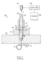
- FIG. 1 is a schematic diagram of my new interferometer set up for single-pass measurement with two diffractive optics.
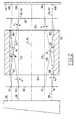
- FIG. 2 is a diagram of the diffractive optics used in the interferometer for measuring internal cylindrical test surfaces.
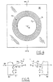
- FIG. 3 is an axial view of an image-forming optic displaying an interference pattern representative of deviations in the test surface.
- FIG. 4 is an axial view of one of the diffractive optics.
- FIG. 5 is a fragmentary cross-sectional view of two diffractive optics.
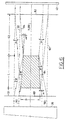
- FIG. 6 is a diagram of diffractive optics used in the interferometer for measuring external conical test surfaces.
- FIG. 1 An embodiment of the invention is illustrated in FIG. 1 as a single-pass interferometer 10, incorporating features of a conventional Mach-Zender interferometer.
- a test piece 12 shown also in FIG. 2, has an inside cylindrical surface 14 under test with an axis of symmetry 15 that is aligned with a reference axis 11 of the interferometer 10.
- the test piece 12 is mounted on an air bearing 16 carried by a surface plate 18 on a base 20.
- the air bearing 16 provides both rotational and translational control over the test piece 12 to permit multiple measures from different positions. Mathematical comparisons between the multiple measures can be used to separate systematic errors.
- a light source 22 such as a laser diode or a HeNe laser, produces a beam of coherent light.
- An optical fiber 24 transmits the beam through the base 20 to a collimator 26 that shapes the beam into a planar primary wavefront 28 represented by selected rays.
- a leading diffractive optic 30, such as a circular transmissive diffraction grating or binary optic, divides the planar wavefront 28 into a reference wavefront 32 and a test wavefront 34.
- the reference wavefront 32 remains a planar wavefront.
- test wavefront 34 is reshaped by the leading diffractive optic 30 into an axiconic wavefront composed of rays that are uniformly inclined to the reference axis 11 through a first diffraction angle " ⁇ ", which is measured within axial planes of the reference axis 11.
- Respective openings 36 and 38 through the air bearing 16 and the surface plate 18 provide clearance enabling the reference and test wavefronts 32 and 34 to propagate along the reference axis 11 through a hollow center of the test piece 12.
- the test wavefront 34 reflects from different positions of the cylindrical test surface 14 at a constant grazing angle " ⁇ ".
- a following diffractive optic 40 further reshapes the reflected test wavefront 34 back into a planar wavefront through a second diffraction angle " ⁇ ".
- the two diffraction angles " ⁇ " and “ ⁇ ” are equal to each other and to the constant grazing angle " ⁇ ".
- both the reference and test wavefronts 32 and 34 emerge from the following diffractive optic 40 as interfering planar wavefronts.
- an image-forming optic 42 images a pattern (referred to as an interferogram) 44 of the interference at the following diffractive optic 40 onto an image-recording device, such as a camera 46.
- the imaged interference pattern 44 which is superimposed on the test surface 14, represents deviations of the test surface 14 from a theoretical cylindrical surface.
- the camera 46 which preferably incorporates a solid state or a charge-coupled device (CCD), records the interference pattern for processing by a computer 48.
- the image-forming optic can be incorporated into the camera 46 or can be provided as one or more separate elements.
- a display device 50 such as a cathode-ray tube, flat panel device, or printer, displays information about the cylindrical test surface 14 in a useful form. In addition to topographical information, derivable measures such as roundness, straightness, taper, and cylindricity could also be displayed. Alternatively, the information could be electronically stored or transmitted for use in another operation, such as feedback to a manufacturing operation.
- FIG. 3 depicts the annular interference pattern 44 that appears at the following diffractive optic 40.
- a reference point 52 in the interference pattern 44 coincides with a point of intersection by the reference axis 11.
- Exemplary points of reflection 54, 56, 58, and 60 from the cylindrical test surface 14 correspond to points 54', 56', 58', and 60' in the interference pattern 44.
- Angles about the reference axis 11 between the points of reflection 54, 56 and 58, 60 from the cylindrical test surface 14 correspond to similar angles between the points 54', 56' and 58', 60' about the reference point 52.
- axial distances along the reference axis 11 between the points of reflection 54, 58 and 56, 60 relate to radial distances between the points 54', 58' and 56', 60' from the reference point 52.
- the points of reflection 54 and 58 at one end 62 of the cylindrical test surface 14 have corresponding points located at a shorter radial distance in the interference pattern 44 than the points of reflection 56 and 60 at the other end 64 of the cylindrical test surface 14.
- phase differences of the cylindrical test surface 14 from the theoretical test surface at the points of reflection 54, 56, 58, and 60 appear as phase differences at the corresponding points 54', 56', 58', and 60' in the interference pattern 44.
- Accurate measures of these phase differences are obtained by conventional phase shifting techniques in which optical path differences between the reference wavefront 32 and the test wavefront 34 are stepped through integer subdivisions of one wavelength. Intensity information at each phase step is stored and a complete phase map is calculated by established Fourier series methods. The stepping can be accomplished in a variety of ways such as by axially translating one of the diffractive optics 30 or 40, preferably the leading optic 30, or by changing the wavelength of the primary wavefront 28.
- Sensitivity of the interferometer 10 which is a measure of the amount of deviation represented by adjacent fringes in the interference pattern 44, decreases with increasing grazing angles " ⁇ ". Accordingly, larger grazing angles " ⁇ " within the range of specular reflection of the test surface 14 are preferred for improving accuracy of individually measured points.
- the camera 46 is preferably arranged with an adjustable focus to equalize the resolution of points imaged along the innermost and outermost circumferences 66 and 68 of the interference pattern 44. Some limitation of the imaging angles seen by the camera 46 may be desirable to control differences between the resolution of points imaged along the innermost and outermost circumferences 66 and 68 of the interference pattern.
- the leading and following diffractive optics 30 and 40 are further illustrated by FIGS. 4 and 5.
- the leading diffractive optic 30 is shown as a diffraction grating having a diffracting pattern formed by a number of concentric closed-shaped grooves 70 for dividing light into two different diffraction orders.
- the following diffractive optic 40 is preferably a similar grating oriented as shown in the fragmentary cross-sectional view of FIG. 5. With the zero diffraction order aligned with the reference axis 11, positive or "+" diffraction orders refer to light rays that are diffracted toward the reference axis 11 and negative or "-" diffraction orders refer to light rays that are diffracted away from the reference axis 11.
- the reference wavefront 32 is transmitted (diffracted) by both diffractive optics 30 and 40 at a zero diffraction order
- the test wavefront 34 is preferably transmitted (diffracted) by both optics 30 and 40 at a first diffraction order.
- the leading diffractive optic 30 is oriented for dividing the reference and test wavefronts 32 and 34
- the following diffractive optic 40 is oriented for combining the two wavefronts 32 and 34.
- the grooves 70 in both gratings are spaced at a constant pitch "p" for uniformly inclining the test beam 34 with respect to the reference beam 32 through the diffraction angles " ⁇ " and " ⁇ ". Sensitivity, as a measure of units per fringe, is equal to one-half of the pitch "p" for first order diffractions of the test wavefront.
- the grooves 70 have paths that are shaped to match transverse sections of the cylindrical test surface 14. For example, inner groove 72 matches the circular section at the far end 64 of the test surface 14, and outer groove 74 matches the circular section at the near end 62 of the test surface 14. Together, the shape and spacing of the grooves 70 represent a mathematical description of the test surface 14.
- Profiles of the grooves 70 can be shaped to control diffraction energies in the zero, first, and higher diffraction orders.
- the grooves 70 can be blazed to concentrate diffraction energies within only two diffraction orders, which are used for diffracting the reference and test wavefronts 32 and 34.
- the depth or width of the grooves 70 can also be varied to appropriately divide the diffraction energies between the interfering reference and test wavefronts 32 and 34 to maximize contrast of the interference pattern 44. Accounting also for the reflectivity of the test surface 14, either or both of the diffractive optics 30 or 40 can be modified to accomplish this.
- the diffractive optics 30 and 40 can be made to high accuracy by photolithographically exposing and etching coatings under computer control. This method of manufacture enables complex mathematical descriptions of test surfaces to be readily embedded into the diffractive optics. Alternatively, the diffractive optics 30 and 40 can be made by etching glass substrates for improving durability or by modifying the underlying substrate to exhibit similar modulations in amplitude or phase.
- FIG. 6 shows an alternative arrangement of the diffractive optics for measuring tapered test surfaces.
- FIG. 6 shows alternative leading and following diffractive optics 80 and 82 for measuring an external conical test surface 84 having a taper angle " ⁇ " with respect to an axis of symmetry 86.
- a planar primary wavefront 90 is split by the leading diffractive optic 80 into a planar reference wavefront 92 and an axiconic test wavefront 94 composed of rays inclined to the reference axis 11 through the first diffraction angle " ⁇ ".
- the test wavefront 94 is reflected by the conical test surface 84 at a constant grazing angle " ⁇ ".
- the following diffractive optic 82 rediffracts the reflected test wavefront 94 through the second diffraction angle " ⁇ " into a planar form aligned with the reference wavefront 92.
- Different relative positions can be used to satisfy other optical or mechanical considerations when the test surface is defined by a surface of revolution.
- the following diffractive optic of FIG. 2 could be positioned beyond a cross-over point of a converging test wavefront to provide better access to the test piece.
- the invention can also be used to measure other and more complex three-dimensional test surfaces, including inside and outside surfaces of non-circular cylinders and cones, involute profiles, and gear teeth.
- the nonlinear paths of the diffractive optics can be varied to match non-circular transverse sections of test surfaces, and the pitch spacing of the grooves can be varied to match curvatures in axial sections of test surfaces.
- the diffractive optics can also be stepped or curved to further shape the wavefronts or to provide focusing qualities. Limited sections of the gratings can be used to measure surfaces that lack an axis of symmetry. Where possible, sensitivity of the interferometer along the reference axis is preferably held constant but can be varied by changing the pitch of the grating grooves.
Landscapes
- Physics & Mathematics (AREA)
- General Physics & Mathematics (AREA)
- Length Measuring Devices By Optical Means (AREA)
- Instruments For Measurement Of Length By Optical Means (AREA)
- Diffracting Gratings Or Hologram Optical Elements (AREA)
Claims (16)
- Interferometer (10) zum Messen von Variationen in einer dreidimensionalen Testfläche (14, 84) mit streifendem Einfall umfassend:dadurch gekennzeichnet, dass die nachfolgende Beugungsoptik (40, 82) die Test-Wellenfront (34, 94) weiter in eine planare Gestalt umformt, die jener der Bezugs-Wellenfront entspricht; und dasseine Lichtquelle (22), die eine primäre Wellenfront (28, 90) mit planarer Gestalt erzeugt;eine vordere Beugungsoptik (30, 80), die (a) die primäre Wellenfront in eine Bezugs-Wellenfront (32, 92) und eine Test-Wellenfront (34, 94) teilt und (b) die Test-Wellenfront (34, 94) in eine nicht-planare Gestalt umformt, die sich von der Bezugs-Wellenfront unterscheidet, um sie von der dreidimensionalen Testfläche (14, 84) in einem streifenden Winkel () zu reflektieren;eine nachfolgende Beugungsoptik (40, 82), die sich von der vorderen Beugungsoptik (30, 80) unterscheidet und die Bezugs- (32, 92) und die Test- (34, 94) Wellenfront wieder kombiniert, um ein Interferenzmuster (44) zwischen der Test-Wellenfront und der Bezugs-Wellenfront zu erzeugen, das Variationen in der Testfläche (14, 84) anzeigt,
eine Bilderzeugungsoptik (42) das Interferenzmuster (44) zwischen der weiter umgeformten Test-Wellenfront und der Bezugs-Wellenfront auf einer Bildaufzeichnungsvorrichtung (46) abbildet. - Interferometer nach Anspruch 1, bei dem die vordere und die nachfolgende Beugungsoptik (80, 82) unterschiedliche Beugungsmuster mit nicht-linearen Wegen aufweisen.
- Interferometer nach Anspruch 2, bei dem die vordere und die nachfolgende Beugungsoptik auf eine gemeinsame Bezugsachse (11) ausgerichtet sind und die durch die vordere Beugungsoptik umgeformte Test-Wellenfront in der Winkelausrichtung um die Bezugsachse variiert.
- Interferometer nach Anspruch 1, bei dem die vordere und die nachfolgende Beugungsoptik ein vorderes und ein nachfolgendes Beugungsgitter sind, die jeweils ungleichmäßig beabstandete Rillen zum relativen Umformen der Test-Wellenfront aufweisen.
- Interferometer nach Anspruch 1, bei dem die vordere Beugungsoptik die Bezugs- und die Test-Wellenfront in unterschiedliche Beugungsordnungen teilt und die nachfolgende Beugungsoptik die Bezugs- und die Test-Wellenfront aus unterschiedlichen Beugungsordnungen wieder kombiniert.
- Interferometer nach Anspruch 5, bei dem zumindest eine aus der vorderen und der nachfolgenden Beugungsoptik (30, 80; 40, 82) angeordnet ist, um Beugungsenergien der wieder kombinierten Bezugs- und Test-Wellenfronten auszugleichen.
- Interferometer nach Anspruch 5, bei dem die Test- und die Bezugs-Wellenfront durch die verschiedenen Beugungsordnungen der vorderen Beugungsoptik (30, 80) durch einen vorderen Beugungswinkel "µ" geteilt werden und die Test- und Bezugs-Wellenfronten durch die verschiedenen Beugungsordnungen der nachfolgenden Beugungsoptik (40, 82) durch einen nachfolgenden Beugungswinkel "v" erneut kombiniert werden, der sich vom vorderen Beugungswinkel "µ" unterscheidet.
- Interferometer nach Anspruch 7, bei dem der vordere und der nachfolgende Beugungswinkel "µ" und "v" mit dem streifenden Winkel (), bei dem die Test-Wellenfront von der Testfläche reflektiert wird, durch die folgende Gleichung in Bezug gesetzt werden:
- Interferometer nach Anspruch 8, bei dem die vordere (30, 80) und die nachfolgende (40, 82) Beugungsoptik mit einer gemeinsamen Bezugsachse (11) ausgerichtet sind und der vordere und der nachfolgende Beugungswinkel "µ" und "v" mit einem Winkel "α", in dem die Testfläche zur Bezugsachse geneigt ist, durch die folgende Gleichung in Bezug gesetzt werden:
- Verfahren zum optischen Messen einer dreidimensionalen Testfläche (14, 84) in einem streifenden Winkel (), folgende Schritte umfassend:das Anordnen der Testfläche (14, 84) entlang eines optischen Wegs zwischen vorderer (30, 80) und nachfolgender (40, 82) Beugungsoptik;das Formen eines Lichtstrahls zu einer primären Wellenfront (28, 90) mit planarer Gestalt;das Teilen der primären Wellenfront in der vorderen Beugungsoptik (30, 80) in eine Test-Wellenfront (34, 94) und eine Bezugs-Wellenfront (32, 92);das Beugen der Test-Wellenfront (34, 94) mit der vorderen Beugungsoptik (30, 80) in eine nicht-planare Gestalt, die sich von jener der Bezugs-Wellenfront (32, 92) unterscheidet;das Reflektieren der gebeugten Test-Wellenfront von der Testfläche (14, 84) mit streifendem Einfall ();das Kombinieren der Test-Wellenfront mit der Bezugs-Wellenfront in der nachfolgenden Beugungsoptik (40, 82), um ein Interferenzmuster (44) zwischen den kombinierten Testund Bezugs-Wellenfronten zu erzeugen, das Variationen in der Testfläche anzeigt;gekennzeichnet durch das weitere Beugen der Test-Wellenfront in der nachfolgenden Beugungsoptik (40, 82) in eine planare Form, die jener der Bezugs-Wellenfront entspricht;das Abbilden des zwischen den kombinierten Test- und Bezugs-Wellenfronten, denen eine planare Form gemeinsam ist, erzeugten interferenzmusters auf eine Bildaufzeichnungsvorrichtung (46); unddas Bewegen einer der Beugungsoptiken (30, 80; 40, 82), zur Phasenverschiebung zwischen der Test- und der Bezugs-Wellenfront.
- Verfahren nach Anspruch 10, bei dem die vordere und die nachfolgende Beugungsoptik jeweils unterschiedliche Beugungsmuster (70, 72, 74) mit nicht-linearen Wegen aufweisen und die Winkelausrichtung der durch die vordere Beugungsoptik umgeformten Test-Wellenfront um eine Ausbreitungsachse (11) variiert.
- Verfahren nach Anspruch 10, bei dem die vordere und die nachfolgende Beugungsoptik mit einer gemeinsamen Bezugsachse ausgerichtet sind, die einem Bezugspunkt im Interferenzmuster entspricht.
- Verfahren nach Anspruch 12, bei dem die Axialabstände entlang der Bezugsachse an Reflexionspunkten der Test-Wellenfront von der Testfläche mit Radialabständen vom Bezugspunkt im Interferenzmuster in Zusammenhang stehen.
- Verfahren nach Anspruch 13, bei dem Winkel um die Bezugsachse an den Reflexionspunkten von der Testfläche mit Winkeln um den Bezugspunkt im Interferenzmuster in Zusammenhang stehen.
- Verfahren nach Anspruch 14, bei dem Variationen der Höhe normal zur Testfläche an den Reflexionspunkten von der Testfläche Phasendifferenzen zwischen der Test- und der Bezugs-Wellenfront im Interferenzmuster entsprechen.
- Verfahren nach Anspruch 10, bei dem die vordere Beugungsoptik auch die primäre Wellenfront in eine Test-Wellenfront und eine Bezugs-Wellenfront teilt und zumindest einer der Beugungsoptiken dazu ausgebildet ist, Beugungsenergien der wieder kombinierten Bezugs- und Test-Wellenfronten auszugleichen.
Priority Applications (1)
| Application Number | Priority Date | Filing Date | Title |
|---|---|---|---|
| DE29623238U DE29623238U1 (de) | 1995-01-19 | 1996-01-18 | Interferometer zur Messung von Oberflächen mit Beugungsoptik mit streifendem Einfall |
Applications Claiming Priority (5)
| Application Number | Priority Date | Filing Date | Title |
|---|---|---|---|
| US37549995A | 1995-01-19 | 1995-01-19 | |
| US375499 | 1995-01-19 | ||
| US08/483,737 US5654798A (en) | 1995-01-19 | 1995-06-07 | Interferometric measurement of surfaces with diffractive optics at grazing incidence |
| US483737 | 1995-06-07 | ||
| PCT/US1996/000707 WO1996022505A1 (en) | 1995-01-19 | 1996-01-18 | Interferometric measurement of surfaces with diffractive optics at grazing incidence |
Publications (2)
| Publication Number | Publication Date |
|---|---|
| EP0804712A1 EP0804712A1 (de) | 1997-11-05 |
| EP0804712B1 true EP0804712B1 (de) | 2002-04-10 |
Family
ID=27007080
Family Applications (1)
| Application Number | Title | Priority Date | Filing Date |
|---|---|---|---|
| EP96903557A Expired - Lifetime EP0804712B1 (de) | 1995-01-19 | 1996-01-18 | Interferometrische messung von oberflächen mit diffraktionsoptik mit streifender inzidenz |
Country Status (5)
| Country | Link |
|---|---|
| US (2) | US5654798A (de) |
| EP (1) | EP0804712B1 (de) |
| JP (1) | JPH10512674A (de) |
| DE (1) | DE69620581T2 (de) |
| WO (1) | WO1996022505A1 (de) |
Families Citing this family (19)
| Publication number | Priority date | Publication date | Assignee | Title |
|---|---|---|---|---|
| DE19602445A1 (de) * | 1996-01-24 | 1997-07-31 | Nanopro Luftlager Produktions | Vorrichtung und Verfahren zum Vermessen von zwei einander gegenüberliegenden Oberflächen eines Körpers |
| US5719676A (en) * | 1996-04-12 | 1998-02-17 | Tropel Corporation | Diffraction management for grazing incidence interferometer |
| DE19643074C2 (de) * | 1996-05-07 | 1999-07-29 | Johannes Prof Dr Schwider | Verfahren zur interferometrischen Prüfung von technischen Oberflächen |
| US6100979A (en) * | 1996-09-09 | 2000-08-08 | Robert Bosch Gmbh | Arrangement for the testing of surfaces |
| US5889591A (en) * | 1996-10-17 | 1999-03-30 | Tropel Corporation | Interferometric measurement of toric surfaces at grazing incidence |
| US5777738A (en) * | 1997-03-17 | 1998-07-07 | Tropel Corporation | Interferometric measurement of absolute dimensions of cylindrical surfaces at grazing incidence |
| US6111643A (en) * | 1997-10-28 | 2000-08-29 | Reliance Electric Industrial Company | Apparatus, system and method for determining wear of an article |
| US7551288B1 (en) | 1997-10-28 | 2009-06-23 | Rockwell Automation Technologies, Inc. | System for monitoring bearing wear |
| US6249351B1 (en) | 1999-06-03 | 2001-06-19 | Zygo Corporation | Grazing incidence interferometer and method |
| US7057741B1 (en) * | 1999-06-18 | 2006-06-06 | Kla-Tencor Corporation | Reduced coherence symmetric grazing incidence differential interferometer |
| AU2001260975A1 (en) * | 2000-01-25 | 2001-08-20 | Zygo Corporation | Optical systems for measuring form and geometric dimensions of precision engineered parts |
| US6304332B1 (en) | 2000-02-17 | 2001-10-16 | Lucent Technologies Inc. | Precision grating period measurement arrangement |
| US7433053B2 (en) * | 2002-08-08 | 2008-10-07 | Applied Materials, Israel, Ltd. | Laser inspection using diffractive elements for enhancement and suppression of surface features |
| DE102010041556A1 (de) | 2010-09-28 | 2012-03-29 | Carl Zeiss Smt Gmbh | Projektionsbelichtungsanlage für die Mikrolithographie und Verfahren zur mikrolithographischen Abbildung |
| DE102013203211A1 (de) * | 2012-06-15 | 2013-12-19 | Dr. Johannes Heidenhain Gmbh | Vorrichtung zur interferentiellen Abstandsmessung |
| US9651358B2 (en) | 2013-08-19 | 2017-05-16 | Corning Incorporated | Grazing-incidence interferometer with dual-side measurement capability using a common image plane |
| TWI486550B (zh) * | 2014-01-20 | 2015-06-01 | Nat Univ Tsing Hua | 厚度線上即時檢測之光學干涉裝置及其方法 |
| KR102381930B1 (ko) * | 2014-03-13 | 2022-04-04 | 내셔널 유니버시티 오브 싱가포르 | 광학 간섭 장치 |
| EP4204758A1 (de) * | 2020-08-27 | 2023-07-05 | ASML Netherlands B.V. | Kompaktes zweidurchgangsinterferometer für ein planspiegelinterferometer |
Family Cites Families (20)
| Publication number | Priority date | Publication date | Assignee | Title |
|---|---|---|---|---|
| DE233644C (de) * | ||||
| DE106769C (de) * | ||||
| DE215388C (de) * | ||||
| DD106769A3 (de) * | 1972-01-04 | 1974-07-05 | Verfahren und anordnung zur pr]fung beliebiger mantelfl[chen rotationssymmetrischer festk\rper mittels synthetischer hologramme | |
| US3907438A (en) * | 1973-06-22 | 1975-09-23 | Gen Electric | Contour measuring system for cylinders |
| US4436424A (en) * | 1981-07-27 | 1984-03-13 | Gca Corporation | Interferometer using transverse deviation of test beam |
| US4391526A (en) * | 1981-08-24 | 1983-07-05 | Itek Corporation | Interferometric surface contour measuring arrangement |
| US4606640A (en) * | 1984-04-02 | 1986-08-19 | The Perkin-Elmer Corporation | Method and apparatus for optically testing cylindrical surfaces |
| DE3471368D1 (en) * | 1984-10-31 | 1988-06-23 | Ibm Deutschland | Interferometric thickness analyzer and measuring method |
| US4678333A (en) * | 1985-05-10 | 1987-07-07 | Nicolet Instrument Corporation | Double-pass optical interferometer |
| JPS62177421A (ja) * | 1986-01-31 | 1987-08-04 | Fuji Photo Optical Co Ltd | 斜入射干渉計装置 |
| US4791584A (en) * | 1986-10-15 | 1988-12-13 | Eastman Kodak Company | Sub-nyquist interferometry |
| US4898470A (en) * | 1988-07-12 | 1990-02-06 | Eastman Kodak Company | Apparatus and method for testing circular cylindrical or conical surfaces |
| US5041726A (en) * | 1990-06-11 | 1991-08-20 | Hughes Aircraft Company | Infrared holographic defect detector |
| JP2619566B2 (ja) * | 1990-11-20 | 1997-06-11 | オ−クマ株式会社 | 光学式位置検出器 |
| JPH04221704A (ja) * | 1990-12-25 | 1992-08-12 | Matsushita Electric Works Ltd | 位相シフト斜入射干渉計 |
| US5220403A (en) * | 1991-03-11 | 1993-06-15 | International Business Machines Corporation | Apparatus and a method for high numerical aperture microscopic examination of materials |
| JP2823707B2 (ja) * | 1991-03-15 | 1998-11-11 | 松下電工株式会社 | 位相シフト斜入射干渉計 |
| US5210591A (en) * | 1991-08-02 | 1993-05-11 | Hughes Aircraft Company | Interferometric ball bearing test station |
| US5268742A (en) * | 1992-06-15 | 1993-12-07 | Hughes Aircraft Company | Full aperture interferometry for grazing incidence optics |
-
1995
- 1995-06-07 US US08/483,737 patent/US5654798A/en not_active Expired - Fee Related
-
1996
- 1996-01-18 DE DE69620581T patent/DE69620581T2/de not_active Expired - Fee Related
- 1996-01-18 WO PCT/US1996/000707 patent/WO1996022505A1/en not_active Ceased
- 1996-01-18 JP JP8522391A patent/JPH10512674A/ja active Pending
- 1996-01-18 EP EP96903557A patent/EP0804712B1/de not_active Expired - Lifetime
-
1997
- 1997-06-30 US US08/885,419 patent/US5909281A/en not_active Expired - Fee Related
Also Published As
| Publication number | Publication date |
|---|---|
| US5654798A (en) | 1997-08-05 |
| JPH10512674A (ja) | 1998-12-02 |
| US5909281A (en) | 1999-06-01 |
| WO1996022505A1 (en) | 1996-07-25 |
| DE69620581T2 (de) | 2002-11-28 |
| DE69620581D1 (de) | 2002-05-16 |
| EP0804712A1 (de) | 1997-11-05 |
Similar Documents
| Publication | Publication Date | Title |
|---|---|---|
| EP0804712B1 (de) | Interferometrische messung von oberflächen mit diffraktionsoptik mit streifender inzidenz | |
| US5737079A (en) | System and method for interferometric measurement of aspheric surfaces utilizing test plate provided with computer-generated hologram | |
| US5793488A (en) | Interferometer with compound optics for measuring cylindrical objects at oblique incidence | |
| CN107816939B (zh) | 衍射光学元件和干涉测量方法 | |
| US7072042B2 (en) | Apparatus for and method of measurement of aspheric surfaces using hologram and concave surface | |
| CN101495833B (zh) | 确定光学表面的实际形状偏离理想形状的偏差的方法和装置 | |
| JP4302512B2 (ja) | 非球面表面および波面に対する干渉計スキャニング | |
| US6226092B1 (en) | Full-field geometrically desensitized interferometer using refractive optics | |
| Nomura et al. | Shape measurements of mirror surfaces with a lateral-shearing interferometer during machine running | |
| JP3185901B2 (ja) | ホログラム干渉計による干渉縞の測定解析方法 | |
| JP3242930B2 (ja) | 環状面の限界入射角での干渉計測法 | |
| US5777738A (en) | Interferometric measurement of absolute dimensions of cylindrical surfaces at grazing incidence | |
| US4693604A (en) | Interference method and interferometer for testing the surface precision of a parabolic mirror | |
| KR100457656B1 (ko) | 위상천이 회절격자 간섭계와 그 측정방법 | |
| JPH116784A (ja) | 非球面形状測定装置および測定方法 | |
| EP0137976A2 (de) | Interferometrische Messtechnik von Oberflächenformen | |
| JP3461566B2 (ja) | 円錐形状測定用干渉計 | |
| Yan et al. | Cophasing calibration for a segmented telescope based on two-dimensional dispersed interferograms | |
| JPH08219737A (ja) | 干渉計 | |
| Palum | Surface profile error measurement for small rotationally symmetric surfaces | |
| JPH03156305A (ja) | 非球面形状測定装置 | |
| JPH0356419B2 (de) | ||
| DE29623238U1 (de) | Interferometer zur Messung von Oberflächen mit Beugungsoptik mit streifendem Einfall | |
| Dörband | 14.1 Tactile Profile Measurement | |
| JPH0447243B2 (de) |
Legal Events
| Date | Code | Title | Description |
|---|---|---|---|
| PUAI | Public reference made under article 153(3) epc to a published international application that has entered the european phase |
Free format text: ORIGINAL CODE: 0009012 |
|
| 17P | Request for examination filed |
Effective date: 19970808 |
|
| AK | Designated contracting states |
Kind code of ref document: A1 Designated state(s): DE GB IT SE |
|
| 17Q | First examination report despatched |
Effective date: 19990805 |
|
| RBV | Designated contracting states (corrected) |
Designated state(s): AT BE CH DE FR GB IT LI SE |
|
| GRAG | Despatch of communication of intention to grant |
Free format text: ORIGINAL CODE: EPIDOS AGRA |
|
| GRAG | Despatch of communication of intention to grant |
Free format text: ORIGINAL CODE: EPIDOS AGRA |
|
| GRAH | Despatch of communication of intention to grant a patent |
Free format text: ORIGINAL CODE: EPIDOS IGRA |
|
| REG | Reference to a national code |
Ref country code: GB Ref legal event code: IF02 |
|
| GRAH | Despatch of communication of intention to grant a patent |
Free format text: ORIGINAL CODE: EPIDOS IGRA |
|
| RBV | Designated contracting states (corrected) |
Designated state(s): DE GB IT SE |
|
| GRAA | (expected) grant |
Free format text: ORIGINAL CODE: 0009210 |
|
| AK | Designated contracting states |
Kind code of ref document: B1 Designated state(s): DE GB IT SE |
|
| REF | Corresponds to: |
Ref document number: 69620581 Country of ref document: DE Date of ref document: 20020516 |
|
| PLBE | No opposition filed within time limit |
Free format text: ORIGINAL CODE: 0009261 |
|
| STAA | Information on the status of an ep patent application or granted ep patent |
Free format text: STATUS: NO OPPOSITION FILED WITHIN TIME LIMIT |
|
| 26N | No opposition filed |
Effective date: 20030113 |
|
| PGFP | Annual fee paid to national office [announced via postgrant information from national office to epo] |
Ref country code: GB Payment date: 20050112 Year of fee payment: 10 |
|
| PGFP | Annual fee paid to national office [announced via postgrant information from national office to epo] |
Ref country code: SE Payment date: 20050120 Year of fee payment: 10 |
|
| PG25 | Lapsed in a contracting state [announced via postgrant information from national office to epo] |
Ref country code: GB Free format text: LAPSE BECAUSE OF NON-PAYMENT OF DUE FEES Effective date: 20060118 |
|
| PG25 | Lapsed in a contracting state [announced via postgrant information from national office to epo] |
Ref country code: SE Free format text: LAPSE BECAUSE OF NON-PAYMENT OF DUE FEES Effective date: 20060119 |
|
| PGFP | Annual fee paid to national office [announced via postgrant information from national office to epo] |
Ref country code: IT Payment date: 20060131 Year of fee payment: 11 |
|
| EUG | Se: european patent has lapsed | ||
| GBPC | Gb: european patent ceased through non-payment of renewal fee |
Effective date: 20060118 |
|
| PGFP | Annual fee paid to national office [announced via postgrant information from national office to epo] |
Ref country code: DE Payment date: 20070228 Year of fee payment: 12 |
|
| PG25 | Lapsed in a contracting state [announced via postgrant information from national office to epo] |
Ref country code: DE Free format text: LAPSE BECAUSE OF NON-PAYMENT OF DUE FEES Effective date: 20080801 |
|
| PG25 | Lapsed in a contracting state [announced via postgrant information from national office to epo] |
Ref country code: IT Free format text: LAPSE BECAUSE OF NON-PAYMENT OF DUE FEES Effective date: 20070118 |