EP0804048B1 - Haut-parleur - Google Patents
Haut-parleur Download PDFInfo
- Publication number
- EP0804048B1 EP0804048B1 EP97105524A EP97105524A EP0804048B1 EP 0804048 B1 EP0804048 B1 EP 0804048B1 EP 97105524 A EP97105524 A EP 97105524A EP 97105524 A EP97105524 A EP 97105524A EP 0804048 B1 EP0804048 B1 EP 0804048B1
- Authority
- EP
- European Patent Office
- Prior art keywords
- loud speaker
- permanent magnets
- permanent magnet
- voice coil
- moving coil
- Prior art date
- Legal status (The legal status is an assumption and is not a legal conclusion. Google has not performed a legal analysis and makes no representation as to the accuracy of the status listed.)
- Expired - Lifetime
Links
Images

Classifications
-
- H—ELECTRICITY
- H04—ELECTRIC COMMUNICATION TECHNIQUE
- H04R—LOUDSPEAKERS, MICROPHONES, GRAMOPHONE PICK-UPS OR LIKE ACOUSTIC ELECTROMECHANICAL TRANSDUCERS; ELECTRIC HEARING AIDS; PUBLIC ADDRESS SYSTEMS
- H04R9/00—Transducers of moving-coil, moving-strip, or moving-wire type
- H04R9/06—Loudspeakers
- H04R9/063—Loudspeakers using a plurality of acoustic drivers
-
- H—ELECTRICITY
- H04—ELECTRIC COMMUNICATION TECHNIQUE
- H04R—LOUDSPEAKERS, MICROPHONES, GRAMOPHONE PICK-UPS OR LIKE ACOUSTIC ELECTROMECHANICAL TRANSDUCERS; ELECTRIC HEARING AIDS; PUBLIC ADDRESS SYSTEMS
- H04R9/00—Transducers of moving-coil, moving-strip, or moving-wire type
- H04R9/02—Details
- H04R9/025—Magnetic circuit
-
- H—ELECTRICITY
- H04—ELECTRIC COMMUNICATION TECHNIQUE
- H04R—LOUDSPEAKERS, MICROPHONES, GRAMOPHONE PICK-UPS OR LIKE ACOUSTIC ELECTROMECHANICAL TRANSDUCERS; ELECTRIC HEARING AIDS; PUBLIC ADDRESS SYSTEMS
- H04R2209/00—Details of transducers of the moving-coil, moving-strip, or moving-wire type covered by H04R9/00 but not provided for in any of its subgroups
- H04R2209/022—Aspects regarding the stray flux internal or external to the magnetic circuit, e.g. shielding, shape of magnetic circuit, flux compensation coils
Definitions
- the invention relates to the formation of speakers, in particular with the formation of drive systems for such speakers as well as the mutual association of such speakers.
- permanent magnets are either formed in one piece or consist of a juxtaposition of permanent magnet segments. Such arrangements are for example WO 93/03586 known. Also in these arrangements there are return elements which guide the magnetic flux provided by the permanent magnets, so that sufficient induction is provided to the annular gap.
- a speaker with two radially magnetized permanent magnets, but without return elements is from the US 4,327,257 known.
- the invention has the object to provide a magnet system which avoids the disadvantages of the prior art.
- the basic idea of the present invention is to use the leakage flux emitted by a radially magnetized permanent magnet to drive a voice coil. This will it is possible to form the receiving parts for the permanent magnet of a para or diamagnetic material. This has the consequence that a considerable space and weight reduction is achieved, since the geometric specifications for the return parts, which must be observed in the prior art for conducting the magnetic flux within these parts, according to the invention are irrelevant. Also, the production of magnetic systems is greatly simplified according to the invention, since operations, which are necessary for connecting the otherwise conventional return parts according to the prior art omitted. Rather, the receiving part according to the invention only forms the rear end of the loudspeaker or a support structure for the permanent magnet and the other components of the loudspeaker.
- receiving parts or units from receiving part and loudspeaker basket As suitable materials for the formation of receiving parts or units from receiving part and loudspeaker basket to offer plastics, metals and metal alloys. It is particularly advantageous to use metal for the formation of receiving parts in the above sense, since these materials simultaneously ensure good heat dissipation in the region of the drive system of the loudspeaker.
- a particularly effective use of the emitted by the permanent magnet leakage flux is given when the magnet system is designed erfingdungshiel.
- the leakage flux emitted by the permanent magnet is utilized by both coils to drive a diaphragm.
- each of these permanent magnets may be surrounded on its inner shell side and / or outer shell side of a voice coil. If additional voice coils are used to drive, for example, a diaphragm, it is necessary to rigidly connect these voice coils.
- the inventive magnet system can be modified so that, for example, all arranged on an inner circumferential surface of the permanent magnet coils for driving a membrane and arranged on all the other lateral surface coils are used to drive another membrane.
- the respective voice coil bobbin is approximately tubular and the first end of this voice coil bobbin is connected to a first diaphragm and the second end of this voice coil bobbin to a second diaphragm and the two membranes, their Suspensions, etc. formed completely identical, such an arrangement can be used as a dipole radiator, for example, to produce a diffused sound field for a Dolby Surround playback.
- Such diffuse sound fields are generated according to the prior art in that two completely identical but inversely polarized loudspeakers with separate volumes are used. With such arrangements, however, the desired effects can only be achieved if the two loudspeakers have a reproduction frequency response identical to one to two dB.
- the respective sound event is perceived as coming from or coming from behind.
- the identity in the playback frequency response can be ensured only by considerable effort in production.
- the arrangement for generating a diffuse sound field according to claim 9 or 10 formed deviations, which are caused for example by production-related membrane differences or unavoidable manufacturing differences in the assembly of the speakers, thereby compensated or averaged that the production-related deviations of all membranes, etc. by a mechanical coupling of both membranes in each operating state are effective.
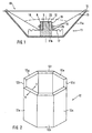
- FIG. 1 a known loudspeaker (10) is shown in section.
- This loudspeaker (10) is essentially formed by a receiving part (11), a permanent magnet (12) and a membrane (13).
- the receiving part (11) from a loudspeaker basket (11 a) and a mandrel (11 b) is formed.
- polycarbonate As a material for the parts (11a and 11b) polycarbonate was used. A restriction to this material is not associated with it. Rather, in another - not shown - example, other plastics, such as ABS, or metals, such as aluminum, can be used as materials, provided that these materials have para or diamagnetic properties.
- dome (11b) is circular in shape, wherein the basket (11a) facing away from the end of the mandrel (11b) opposite the basket (11a) near the end has a smaller diameter.
- This formation of the dome (11b) serves for the positive reception of the annular permanent magnet (12).
- the mandrel (11b) does not necessarily have to completely or partially fill the inner diameter of the permanent magnet (12).
- FIG FIG. 4 An embodiment in which the mandrel (11b) does not completely fill the inner diameter of the permanent magnet (12) is shown in FIG FIG. 4 shown.
- basket (11 a) is a conical membrane (13) is inserted.
- the upper end of the membrane (13) is connected by means of a bead (14) with the basket (11 a).
- the lower end of the membrane (13) has a voice coil former (15) which projects into the space surrounded by the membrane (13).
- the Sehwingspule (16) is wound.
- Finer is a centering diaphragm (17) is provided which is connected to the basket (11 a) and the membrane (13) and which holds the voice coil (16) centrally to the longitudinal axis of the magnet system and the speaker (10).
- the mandrel (11b), the permanent magnet (12) and the voice coil (16) by means of a dust cover (18) may be covered.
- This Staubschutzkalotte (18) has in conventional speakers (10) the task of protecting the narrow annular gap from particle accumulation.
- This object is also the dust cap (18) used in the system according to the invention, although in the systems according to the invention, which exploit the leakage flux, the distances between the voice coil (16) and the permanent magnet (12) are not so critical, so that when Dust cover is not present, the accumulating particles are of minor importance.
- the drive of the current-carrying voice coil (16) takes place in the stray field, which is generated by a radially magnetized permanent magnet (12). Therefore lies in the embodiment according to Fig. 1 the north pole (N) on the outer lateral surface (19) and the south pole (S) on the inner lateral surface (20) of the permanent magnet (12).
- the induction of radially magnetized permanent magnets (12) along the lateral surfaces 19/20 is constant, so that the voice coil (16) moves in a homogeneous magnetic field over its entire deflection path, which ultimately leads to a very linear operation of the loudspeaker (FIG. 10) leads.
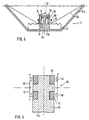
- permanent magnets (12) are not limited to the one-piece circular ring shape.
- a permanent magnet (12) is shown which octagonal is formed and consists of a juxtaposition of permanent magnet segments (12a-h). Each of these segments (12a-h) is also radially magnetized as indicated on the segment (12a).
- the use of segmented permanent magnets (12) has the advantage that plate material can be used which can be magnetized more easily in relation to annular permanent magnets (12).
- octagonal shape of the permanent magnet (12) is only an example.
- the permanent magnet (12) may also be cuboid formed by the juxtaposition of only 4 segments.
- a speaker (10) is shown, the deviating from the training according to Fig. 1 has two voice coil bobbins (15 and 15 '). These two voice coil bobbins (15, 15 ') are connected by a circular disk (21) at a mutual distance. In addition, each of the two voice coil bobbins (15, 15 ') is provided with a voice coil (16, 16').
- the mandrel (11b) is provided at its end remote from the basket (11a) with a disc (22), which is also formed of a para or diamagnetic material.
- the underside (23) of the disc (22) is connected to a radially magnetized Dauelmagneten (12) in a circular ring shape.
- the disc (22) may also be formed of a ferro-magnetic material, although such material selection leads to a somewhat poorer efficiency.
- annular permanent magnet (12) Since the inner diameter of the annular permanent magnet (12) is greater than the outer diameter of the mandrel (11b) and both parts are coaxial with each other, an "air gap” (24) is formed. In this "air gap” (24) immersed with the coil (16) voice coil carrier (15), while the voice coil (15 ') arranged voice coil (16'), the outer surface (19) of the permanent magnet (12) at a distance border.
- loudspeakers (10) without major changes
- the devices can be used, which is also used for the preparation of arrangements according to DE-A-4113017 be used.
- the devices according to the invention for centering and fixing the membrane (13) in the basket (11a) commonly used Zentrierhülsen which for producing loudspeakers (10) between the pole core ⁇ mandrel (11b) and permanent magnet (12) ⁇ and the Voice coil carrier (15) can be used.
- the training according to Fig. 3 but with the two voice coils (16, 16 ') is not limited to the drive of only one membrane (13). Rather, the leakage flux of the radially magnetized permanent magnet (12) can also be used to drive different membranes (13, 13 '). Such conditions are in Fig. 4 shown. It is different from the representation according to the Fig. 1 the permanent magnet ring (12) placed on the mandrel (11b). Between the inner circumferential surface (20) of the radially magnetized permanent magnet ring (12) and the mandrel (11b) there is an "air gap" (24) in which a voice coil former (15 ') which is wound with a voice coil (16') is immersed. The upper end of the voice coil bobbin (15 ') is provided with a dome-shaped membrane (13'). The outer edge of the dome-shaped membrane (13 ') is connected to the upper end of the permanent magnet (12).
- both voice coils (16, 16') in this embodiment should be reversed in polarity with the audio signal source, if both coils (16, 16 ') are made of manufacturing technology, for example Have the same sense of winding.
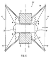
- Fig. 5 shows one opposite Fig. 1 modified mandrel-permanent magnet combination.
- two permanent magnets (12, 12 ') are provided with mutual axial distance on the mandrel (11b).
- Each of these permanent magnets (12, 12 ') is radially magnetized, wherein the same poles of the two permanent magnets (12, 12') point in the same direction.
- the outer lateral surfaces (19) of the two permanent magnets (12, 12 ') a voice coil carrier (16) is juxtaposed, on which also with mutual axial distance two voice coils (16,16') are attached.
- Such an arrangement is to be selected when the stray flux of only one permanent magnet (12) alone is not sufficient to drive a diaphragm (13). If the two coils (16, 16 ') are to be used to drive only one diaphragm (13), the direction of current flow in both voice coils (16, 16') must be in the same direction.
- Fig. 5 By the voice coil carrier (15) intersecting double dotted dashed lines is indicated that the in Fig. 5 arrangement shown can also be used to drive different membranes (13) when the two voice coils (16, 16 ') are not arranged on a common voice coil bobbin (15), but have independent voice coil bobbin (15'').
- mandrel (11 b) according to Fig. 5 completely fills the inner diameter of the two permanent magnets (12, 12 '). Rather, the in Fig. 5 shown mandrel (11b) also according to the in Fig. 3 and 4 shown embodiments are modified.
- one relating to the FIGS. 1 and 5 shown mandrel-permanent magnet combination can be formed very advantageous in that the one or more permanent magnets (12, 12 ') are inserted into an injection mold, so that the connection of the permanent magnet (12, 12') at the same time with the formation of the mandrel (11b ) or the mandrel (11b) and basket (11a) existing receptacle (11) can take place.
- a dipole radiator (10 ') is shown, which shows a loudspeaker (10'') to the right and left of the double-dotted dashed line.
- Each of these loudspeakers (10 '') essentially corresponds to one in DE-A-4113017 ( Fig. 1 ) shown speakers. Deviating from this, however, is in Fig. 6 formed the magnet system. This is characterized in that it is formed by a radially magnetized permanent magnet (12). Because the first end (25) of the voice coil bobbin (15) is connected to a diaphragm (13) and the second end (25 ') of the voice coil bobbin (15) is connected to another diaphragm (13').
Landscapes
- Physics & Mathematics (AREA)
- Engineering & Computer Science (AREA)
- Acoustics & Sound (AREA)
- Signal Processing (AREA)
- Audible-Bandwidth Dynamoelectric Transducers Other Than Pickups (AREA)
- Electrostatic, Electromagnetic, Magneto- Strictive, And Variable-Resistance Transducers (AREA)
- Chair Legs, Seat Parts, And Backrests (AREA)
- Liquid Crystal (AREA)
- Surgical Instruments (AREA)
Claims (10)
- Haut-parleur, comprenant
un système magnétique qui comprend au moins deux aimants permanents (12, 12') qui sont aimantés transversalement à l'axe longitudinal du système magnétique, et
des parties de réception (11, 11b) qui portent les aimants permanents (12, 12') ou sont reliés à ceux-ci, dans lequel les parties de réception (11, 11 b) sont formées exclusivement à partir d'un matériau qui présente des propriétés paramagnétiques ou diamagnétiques,
caractérisé en ce que
les aimants permanents (12, 12') sont réalisés comme un profilé creux avec une surface latérale intérieure et une surface latérale extérieure (19, 20),
en ce qu'il existe une première bobine mobile (16) qui est disposée à une distance radiale par rapport à l'une des deux surfaces latérales (19, 20) des aimants permanents (12, 12'),
en ce qu'il existe une deuxième bobine mobile (16') qui est disposée à une distance radiale par rapport à l'une des deux surfaces latérales des aimants permanents (12, 12'), et
en ce que les deux aimants permanents (12, 12') sont disposés à une distance axiale mutuelle l'un par rapport à l'autre, par rapport à l'axe longitudinal du système magnétique. - Haut-parleur selon la revendication 1, caractérisé en ce qu'il existe au moins un châssis de haut-parleur (11a), et en ce que les parties de réception respectives (11b) et le châssis de haut-parleur (11a) sont réalisés d'une seule pièce.
- Haut-parleur selon la revendication 1 ou 2, caractérisé en ce que les parties de réception (11a, 11b) ou la réalisation d'une seule pièce des parties de réception (11b) et du châssis de haut-parleur (11a) sont formées en métal ou d'un alliage de métal.
- Haut-parleur selon l'une quelconque des revendications 1 à 3, caractérisé en ce que l'aimant permanent respectif (12, 12') est réalisé d'une seule pièce sous la forme d'un anneau de cercle.
- Haut-parleur selon l'une quelconque des revendications 1 à 3, caractérisé en ce que l'aimant permanent respectif (12, 12') se compose d'une pluralité de segments d'aimant permanent (12a à h) adjacents latéralement et formant le profilé creux.
- Haut-parleur selon l'une quelconque des revendications 1 à 5, caractérisé en ce que les deux bobines mobiles (16, 16') sont espacées en direction de la même surface latérale des aimants permanents (12, 12').
- Haut-parleur selon l'une quelconque des revendications 1 à 5, caractérisé en ce que les deux bobines mobiles (16, 16') sont espacées en direction de différentes surfaces latérales des aimants permanents (12, 12').
- Haut-parleur selon l'une quelconque des revendications 1 à 6, caractérisé en ce que les bobines mobiles (16, 16') respectivement disposées sur les mêmes surfaces latérales (19, 20) des deux aimants permanents (12, 12') sont reliées ensemble rigidement.
- Haut-parleur selon l'une quelconque des revendications 2 à 6, caractérisé en ce que chaque bobine mobile (16, 16') est disposée sur un support de bobine mobile (15, 15'), dans lequel dans le cas de bobines mobiles (16, 16') disposées à une distance axiale les unes par rapport aux autres, les bobines mobiles (16, 16') disposées respectivement sur la même surface latérale partagent un support de bobine mobile commun (15), en ce que chaque support de bobine mobile (15, 15') présente une première extrémité (25) et une deuxième extrémité (25'), et en ce qu'au moins la première extrémité (25) est reliée à une membrane (13, 13').
- Haut-parleur selon la revendication 9, caractérisé en ce que la première extrémité (25) est reliée à une première membrane (13) et la deuxième extrémité (25') est reliée à une deuxième membrane (13'), et en ce que les deux membranes (13, 13') sont réalisées de façon identique.
Applications Claiming Priority (2)
| Application Number | Priority Date | Filing Date | Title |
|---|---|---|---|
| DE19616794A DE19616794B4 (de) | 1996-04-26 | 1996-04-26 | Lautsprecher |
| DE19616794 | 1996-04-26 |
Publications (3)
| Publication Number | Publication Date |
|---|---|
| EP0804048A2 EP0804048A2 (fr) | 1997-10-29 |
| EP0804048A3 EP0804048A3 (fr) | 2004-07-14 |
| EP0804048B1 true EP0804048B1 (fr) | 2008-10-29 |
Family
ID=7792585
Family Applications (1)
| Application Number | Title | Priority Date | Filing Date |
|---|---|---|---|
| EP97105524A Expired - Lifetime EP0804048B1 (fr) | 1996-04-26 | 1997-04-03 | Haut-parleur |
Country Status (4)
| Country | Link |
|---|---|
| US (1) | US6359997B2 (fr) |
| EP (1) | EP0804048B1 (fr) |
| AT (1) | ATE413081T1 (fr) |
| DE (2) | DE19616794B4 (fr) |
Families Citing this family (22)
| Publication number | Priority date | Publication date | Assignee | Title |
|---|---|---|---|---|
| US5802191A (en) * | 1995-01-06 | 1998-09-01 | Guenther; Godehard A. | Loudspeakers, systems, and components thereof |
| GB2334849B (en) * | 1998-02-27 | 2001-02-28 | Simon James Norfolk | The double diaphragm |
| US8588457B2 (en) | 1999-08-13 | 2013-11-19 | Dr. G Licensing, Llc | Low cost motor design for rare-earth-magnet loudspeakers |
| US20020150275A1 (en) * | 2000-06-27 | 2002-10-17 | Guenther Godehard A. | Low profile speaker and system |
| GB2377849A (en) * | 2001-07-21 | 2003-01-22 | Kh Technology Corp | Loudspeaker drive units with smooth transition to surround |
| JP3963173B2 (ja) * | 2004-01-06 | 2007-08-22 | ソニー株式会社 | スピーカ |
| US7570774B2 (en) * | 2004-05-25 | 2009-08-04 | Estec Corporation | Speaker having improved sound-radiating function to both directions |
| EP1790192A4 (fr) * | 2004-09-09 | 2010-06-02 | Godehard A Guenther | Haut-parleurs et systemes |
| US7706563B2 (en) * | 2005-12-19 | 2010-04-27 | Harman International Industries, Incorporated | Concentric radial ring motor |
| US20070297639A1 (en) * | 2006-06-21 | 2007-12-27 | Noll Michael A | Multiple magnet loudspeaker |
| US8189840B2 (en) | 2007-05-23 | 2012-05-29 | Soundmatters International, Inc. | Loudspeaker and electronic devices incorporating same |
| FR2956274B1 (fr) * | 2010-02-10 | 2017-06-09 | Renault Sas | Structure de transducteur electrodynamique et son procede de fabrication |
| FR2960738B1 (fr) * | 2010-05-28 | 2015-09-25 | Focal Jmlab | Haut-parleur acoustique |
| DE102010045290B4 (de) * | 2010-09-14 | 2016-04-28 | Günther Zimmer | Vereinzler mit elektrodynamischem Stellglied |
| US8836276B2 (en) * | 2011-03-07 | 2014-09-16 | Eldon Technology Limited | Charging batteries for electronic devices by talking |
| CN102821342A (zh) * | 2011-06-10 | 2012-12-12 | 宁波升亚电子有限公司 | 一种扬声器 |
| ITPD20110191A1 (it) | 2011-06-13 | 2012-12-14 | Maurizio Servadio | Trasduttore elettromeccanico/elettroacustico sottile |
| FR3015671B1 (fr) * | 2013-12-23 | 2020-03-20 | Safran Helicopter Engines | Ensemble pour turbomachine pour mesurer des vibrations subies par une pale en rotation |
| CN105025421A (zh) * | 2014-04-17 | 2015-11-04 | 有限会社左尔佐 | 扬声器 |
| US9854365B2 (en) * | 2016-04-15 | 2017-12-26 | Harman International Industries, Inc. | Loudspeaker motor and suspension system |
| CN108513238A (zh) * | 2018-05-22 | 2018-09-07 | 黄清山 | 一种鼓纸及具有该鼓纸的喇叭 |
| CN108632728B (zh) | 2018-06-25 | 2020-08-11 | 歌尔股份有限公司 | 发声器件及便携终端 |
Citations (1)
| Publication number | Priority date | Publication date | Assignee | Title |
|---|---|---|---|---|
| US4327257A (en) * | 1979-09-10 | 1982-04-27 | Schwartz Leslie H | Alignment device for electro-acoustical transducers |
Family Cites Families (25)
| Publication number | Priority date | Publication date | Assignee | Title |
|---|---|---|---|---|
| JPS4811888B1 (fr) * | 1968-07-18 | 1973-04-17 | ||
| US3665352A (en) * | 1970-05-12 | 1972-05-23 | Deutsche Edelstahlwerke Ag | Permanent magnet system for a loudspeaker |
| BE794025A (fr) * | 1972-01-21 | 1973-05-02 | Gen Electric | Ensemble aimante |
| DE2709972A1 (de) * | 1977-03-08 | 1978-09-14 | Wilhelm Dr Ing Lepper | Neuer dynamischer lautsprecher |
| FR2477821A1 (fr) * | 1980-03-06 | 1981-09-11 | 3A Art Acoustique Appliquee Sa | Haut-parleur electrodynamique |
| US4319096A (en) * | 1980-03-13 | 1982-03-09 | Winey James M | Line radiator ribbon loudspeaker |
| NL8301653A (nl) * | 1983-05-10 | 1984-12-03 | Philips Nv | Elektro-akoestische omzetter met een luchtdoorlatend membraan. |
| DK156454C (da) * | 1985-01-03 | 1990-01-15 | Johan Peter Lyngdorf | Hoejttalerenhed med mere end en bas/mellemtone-hoejttaler |
| DE3611120A1 (de) * | 1986-04-03 | 1987-10-08 | Hans Buerk | Lautsprechersystem fuer gleichmaessige rundumabstrahlung hoeherer schallfrequenzanteile |
| JPH01258589A (ja) * | 1988-04-08 | 1989-10-16 | Shicoh Eng Co Ltd | 動電型電気音響交換器 |
| JPH0338999A (ja) * | 1989-07-05 | 1991-02-20 | Matsushita Electric Ind Co Ltd | スピーカ |
| US5142260A (en) * | 1991-03-08 | 1992-08-25 | Harman International Industries, Incorporated | Transducer motor assembly |
| WO1993003586A1 (fr) | 1991-08-05 | 1993-02-18 | Aura Systems, Inc. | Organe de commande de bobine mobile de haut-parleur |
| US5321762A (en) * | 1991-08-05 | 1994-06-14 | Aura Systems, Inc. | Voice coil actuator |
| DE4215519C1 (en) * | 1992-05-12 | 1993-09-23 | Richt, Oskar Hubert, 82319 Starnberg, De | Hi-fi loudspeaker with foil membrane - has coils attached to membrane corresponding to radial magnetic field lines of concentric magnetic rings of drive system |
| DE4234069A1 (de) | 1992-10-09 | 1994-04-14 | Nokia Deutschland Gmbh | Konuslautsprecher in Leichtbauweise |
| KR950024611A (ko) * | 1994-01-05 | 1995-08-21 | 구쯔자와 겐따로우 | 자기회로를 구비한 스피커 |
| CA2147684C (fr) * | 1994-04-25 | 1998-12-08 | Akihiro Furuta | Haut-parleur |
| JP3161677B2 (ja) * | 1995-02-17 | 2001-04-25 | アルパイン株式会社 | スピーカ |
| KR19980032013A (ko) * | 1995-12-15 | 1998-07-25 | 모리시타요오이찌 | 진동 발생장치 |
| US5786741A (en) * | 1995-12-21 | 1998-07-28 | Aura Systems, Inc. | Polygon magnet structure for voice coil actuator |
| US5809157A (en) * | 1996-04-09 | 1998-09-15 | Victor Lavrov | Electromagnetic linear drive |
| US5805907A (en) | 1996-10-04 | 1998-09-08 | International Business Machines Corporation | System and method for reducing power consumption in an electronic circuit |
| JPH11177198A (ja) * | 1997-12-12 | 1999-07-02 | Mitsumi Electric Co Ltd | フレキシブル配線基板 |
| JPH11268598A (ja) * | 1998-03-20 | 1999-10-05 | Inoac Corporation:Kk | モールディングの取付構造 |
-
1996
- 1996-04-26 DE DE19616794A patent/DE19616794B4/de not_active Expired - Lifetime
-
1997
- 1997-04-03 DE DE59712977T patent/DE59712977D1/de not_active Expired - Lifetime
- 1997-04-03 AT AT97105524T patent/ATE413081T1/de not_active IP Right Cessation
- 1997-04-03 EP EP97105524A patent/EP0804048B1/fr not_active Expired - Lifetime
- 1997-04-17 US US08/843,987 patent/US6359997B2/en not_active Expired - Lifetime
Patent Citations (1)
| Publication number | Priority date | Publication date | Assignee | Title |
|---|---|---|---|---|
| US4327257A (en) * | 1979-09-10 | 1982-04-27 | Schwartz Leslie H | Alignment device for electro-acoustical transducers |
Also Published As
| Publication number | Publication date |
|---|---|
| EP0804048A3 (fr) | 2004-07-14 |
| ATE413081T1 (de) | 2008-11-15 |
| US6359997B2 (en) | 2002-03-19 |
| DE19616794A1 (de) | 1997-10-30 |
| EP0804048A2 (fr) | 1997-10-29 |
| DE19616794B4 (de) | 2005-09-29 |
| DE59712977D1 (de) | 2008-12-11 |
| US20010043715A1 (en) | 2001-11-22 |
Similar Documents
| Publication | Publication Date | Title |
|---|---|---|
| EP0804048B1 (fr) | Haut-parleur | |
| DE19654156C2 (de) | Lautsprechereinheit und die Lautsprechereinheit verwendendes Lautsprechersystem | |
| DE68928871T2 (de) | Dynamischer Lautsprecher | |
| DE60201885T2 (de) | Elektroakustischer wandler | |
| EP0591837B1 (fr) | Système d'aimant pour un haut-parleur à construction allégée | |
| DE19913558A1 (de) | Lautsprechervorrichtung | |
| DE3730305C1 (de) | Lautsprecher | |
| DE4317775C2 (de) | Lautsprecher | |
| DE69413098T2 (de) | Lautsprecherstruktur | |
| EP0062600A1 (fr) | Haut-parleur électrodynamique pour fréquences sonores basses et moyennes | |
| DE2808578B2 (de) | Elektrodynamischer Lautsprecher | |
| DE1941569C3 (de) | Elektromagnetischer Mehrkanal-Tonabnehmer | |
| EP3065420A1 (fr) | Convertisseur de signal electromagnetique pour un ossivibrateur | |
| EP0492142B1 (fr) | Système de commande pour un haut-parleur basse fréquence à excursion large | |
| DE2362001A1 (de) | Dynamischer lautsprecher mit schwingspule | |
| DE2637412A1 (de) | Elektromagnetischer wandler | |
| DE3046551C2 (fr) | ||
| EP0471990B1 (fr) | Haut-parleur à double bobine | |
| DE2941615A1 (de) | Lautsprecher | |
| EP0208907B1 (fr) | Système magnétique pour haut-parleur dynamique | |
| DE19851748A1 (de) | Lautsprecher | |
| DE19523682A1 (de) | Lautsprecher | |
| DE19747955A1 (de) | Lautsprecher | |
| DE2409041A1 (de) | Magnetischer tonnabnehmer | |
| DE4225854A1 (de) | Mittel-/Tiefton-Lautsprecher |
Legal Events
| Date | Code | Title | Description |
|---|---|---|---|
| PUAI | Public reference made under article 153(3) epc to a published international application that has entered the european phase |
Free format text: ORIGINAL CODE: 0009012 |
|
| AK | Designated contracting states |
Kind code of ref document: A2 Designated state(s): AT BE DE FR GB IT NL |
|
| RAP1 | Party data changed (applicant data changed or rights of an application transferred) |
Owner name: HARMAN AUDIO ELECTRONIC SYSTEMS GMBH |
|
| PUAL | Search report despatched |
Free format text: ORIGINAL CODE: 0009013 |
|
| AK | Designated contracting states |
Kind code of ref document: A3 Designated state(s): AT BE DE FR GB IT NL |
|
| 17P | Request for examination filed |
Effective date: 20041015 |
|
| RAP1 | Party data changed (applicant data changed or rights of an application transferred) |
Owner name: HARMAN BECKER AUTOMOTIVE SYSTEMS GMBH |
|
| 17Q | First examination report despatched |
Effective date: 20060926 |
|
| GRAP | Despatch of communication of intention to grant a patent |
Free format text: ORIGINAL CODE: EPIDOSNIGR1 |
|
| GRAS | Grant fee paid |
Free format text: ORIGINAL CODE: EPIDOSNIGR3 |
|
| GRAA | (expected) grant |
Free format text: ORIGINAL CODE: 0009210 |
|
| AK | Designated contracting states |
Kind code of ref document: B1 Designated state(s): AT BE DE FR GB IT NL |
|
| REG | Reference to a national code |
Ref country code: GB Ref legal event code: FG4D Free format text: NOT ENGLISH |
|
| REF | Corresponds to: |
Ref document number: 59712977 Country of ref document: DE Date of ref document: 20081211 Kind code of ref document: P |
|
| NLV1 | Nl: lapsed or annulled due to failure to fulfill the requirements of art. 29p and 29m of the patents act | ||
| PG25 | Lapsed in a contracting state [announced via postgrant information from national office to epo] |
Ref country code: NL Free format text: LAPSE BECAUSE OF FAILURE TO SUBMIT A TRANSLATION OF THE DESCRIPTION OR TO PAY THE FEE WITHIN THE PRESCRIBED TIME-LIMIT Effective date: 20081029 |
|
| PLBE | No opposition filed within time limit |
Free format text: ORIGINAL CODE: 0009261 |
|
| STAA | Information on the status of an ep patent application or granted ep patent |
Free format text: STATUS: NO OPPOSITION FILED WITHIN TIME LIMIT |
|
| 26N | No opposition filed |
Effective date: 20090730 |
|
| BERE | Be: lapsed |
Owner name: HARMAN BECKER AUTOMOTIVE SYSTEMS G.M.B.H. Effective date: 20090430 |
|
| PG25 | Lapsed in a contracting state [announced via postgrant information from national office to epo] |
Ref country code: BE Free format text: LAPSE BECAUSE OF NON-PAYMENT OF DUE FEES Effective date: 20090430 |
|
| PG25 | Lapsed in a contracting state [announced via postgrant information from national office to epo] |
Ref country code: AT Free format text: LAPSE BECAUSE OF NON-PAYMENT OF DUE FEES Effective date: 20090403 |
|
| REG | Reference to a national code |
Ref country code: FR Ref legal event code: PLFP Year of fee payment: 19 |
|
| PGFP | Annual fee paid to national office [announced via postgrant information from national office to epo] |
Ref country code: GB Payment date: 20150427 Year of fee payment: 19 Ref country code: DE Payment date: 20150429 Year of fee payment: 19 |
|
| PGFP | Annual fee paid to national office [announced via postgrant information from national office to epo] |
Ref country code: FR Payment date: 20150417 Year of fee payment: 19 Ref country code: IT Payment date: 20150428 Year of fee payment: 19 |
|
| REG | Reference to a national code |
Ref country code: DE Ref legal event code: R119 Ref document number: 59712977 Country of ref document: DE |
|
| GBPC | Gb: european patent ceased through non-payment of renewal fee |
Effective date: 20160403 |
|
| REG | Reference to a national code |
Ref country code: FR Ref legal event code: ST Effective date: 20161230 |
|
| PG25 | Lapsed in a contracting state [announced via postgrant information from national office to epo] |
Ref country code: DE Free format text: LAPSE BECAUSE OF NON-PAYMENT OF DUE FEES Effective date: 20161101 Ref country code: GB Free format text: LAPSE BECAUSE OF NON-PAYMENT OF DUE FEES Effective date: 20160403 Ref country code: FR Free format text: LAPSE BECAUSE OF NON-PAYMENT OF DUE FEES Effective date: 20160502 |
|
| PG25 | Lapsed in a contracting state [announced via postgrant information from national office to epo] |
Ref country code: IT Free format text: LAPSE BECAUSE OF NON-PAYMENT OF DUE FEES Effective date: 20160403 |