EP0803942B1 - Buchse zum Verbinden eines elektrischen Gerätes mit einem Steckverbinder - Google Patents
Buchse zum Verbinden eines elektrischen Gerätes mit einem Steckverbinder Download PDFInfo
- Publication number
- EP0803942B1 EP0803942B1 EP97106934A EP97106934A EP0803942B1 EP 0803942 B1 EP0803942 B1 EP 0803942B1 EP 97106934 A EP97106934 A EP 97106934A EP 97106934 A EP97106934 A EP 97106934A EP 0803942 B1 EP0803942 B1 EP 0803942B1
- Authority
- EP
- European Patent Office
- Prior art keywords
- socket
- inner cylinder
- conductive terminal
- cylinder
- core
- Prior art date
- Legal status (The legal status is an assumption and is not a legal conclusion. Google has not performed a legal analysis and makes no representation as to the accuracy of the status listed.)
- Expired - Lifetime
Links
- 238000003780 insertion Methods 0.000 claims description 20
- 230000037431 insertion Effects 0.000 claims description 20
- 239000011347 resin Substances 0.000 claims description 8
- 229920005989 resin Polymers 0.000 claims description 8
- 238000000465 moulding Methods 0.000 claims description 7
- 238000000034 method Methods 0.000 claims description 4
- 238000004519 manufacturing process Methods 0.000 claims description 3
- 239000002184 metal Substances 0.000 claims 1
- 238000005192 partition Methods 0.000 claims 1
- 230000000717 retained effect Effects 0.000 claims 1
- 238000005452 bending Methods 0.000 description 3
- 238000012986 modification Methods 0.000 description 3
- 230000004048 modification Effects 0.000 description 3
- 230000000295 complement effect Effects 0.000 description 1
- 238000011109 contamination Methods 0.000 description 1
- 238000003825 pressing Methods 0.000 description 1
Images


Classifications
-
- H—ELECTRICITY
- H01—ELECTRIC ELEMENTS
- H01R—ELECTRICALLY-CONDUCTIVE CONNECTIONS; STRUCTURAL ASSOCIATIONS OF A PLURALITY OF MUTUALLY-INSULATED ELECTRICAL CONNECTING ELEMENTS; COUPLING DEVICES; CURRENT COLLECTORS
- H01R43/00—Apparatus or processes specially adapted for manufacturing, assembling, maintaining, or repairing of line connectors or current collectors or for joining electric conductors
- H01R43/20—Apparatus or processes specially adapted for manufacturing, assembling, maintaining, or repairing of line connectors or current collectors or for joining electric conductors for assembling or disassembling contact members with insulating base, case or sleeve
- H01R43/24—Assembling by moulding on contact members
-
- H—ELECTRICITY
- H01—ELECTRIC ELEMENTS
- H01R—ELECTRICALLY-CONDUCTIVE CONNECTIONS; STRUCTURAL ASSOCIATIONS OF A PLURALITY OF MUTUALLY-INSULATED ELECTRICAL CONNECTING ELEMENTS; COUPLING DEVICES; CURRENT COLLECTORS
- H01R33/00—Coupling devices specially adapted for supporting apparatus and having one part acting as a holder providing support and electrical connection via a counterpart which is structurally associated with the apparatus, e.g. lamp holders; Separate parts thereof
- H01R33/05—Two-pole devices
- H01R33/06—Two-pole devices with two current-carrying pins, blades or analogous contacts, having their axes parallel to each other
-
- H—ELECTRICITY
- H01—ELECTRIC ELEMENTS
- H01R—ELECTRICALLY-CONDUCTIVE CONNECTIONS; STRUCTURAL ASSOCIATIONS OF A PLURALITY OF MUTUALLY-INSULATED ELECTRICAL CONNECTING ELEMENTS; COUPLING DEVICES; CURRENT COLLECTORS
- H01R2201/00—Connectors or connections adapted for particular applications
- H01R2201/08—Connectors or connections adapted for particular applications for halogen lamps
Definitions
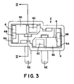
- socket 1 comprises core 2, outer cylindrical shell 3, and connector receiver 16.
- Core 2 includes conductive terminal 6 which extends through terminal hole 8 and into connector receiver 16.
- Core 2 is provided with bulb insertion opening 5 at the end opposite terminal hole 8.
- Conductive terminal 6 comprises wall plate 6A, pressing piece 6B, long elastic piece 6C, and short elastic piece 6D.
- Connector contact 6E extends into connector receiver 16 and is provided with bending section 6F which is more pliable than the remaining sections of conductive terminal 6.
- Outer cylinder 10 surrounds inner cylinder 4 and is provided with overflow groove 12 adjacent insertion opening 5.
- the overflow groove is intended to receive any resin which would otherwise enter the space within inner cylinder 4 and thus impair the integrity of the connection between conductive terminal 6 and the bulb being inserted (not shown).
- Core 2 is provided, at the end remote from opening 5, with projection 7 and projecting rim 9 which serve to lock core 2 within outer cylinder 10.
- outer shell 13 is provided with flange 15 and four engagement projections 14.
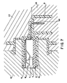
- the socket is best manufactured by insertion molding.
- core 2 is placed in molds K1, K2, and K3.
- the molds have cavities such that they are adapted to produce outer shell 3, outer cylinder 10, and connector insertion portion 16.
- Mold K1 is provided with molding surface 18 and projection rim 19. The former is in contact with insertion opening 5 of core 2 and effectively prevents resin from contacting conductive terminal 6.
- projection rim 19 forms overflow groove 12 (see Figure 1 ) to receive excess resin.
- Conductive terminal 6 is inserted through insertion opening 5 into inner cylinder 4.
- Connector terminal 6E and bending portion 6F are as shown in solid lines in Figure 2 . This makes it easy to pass these portions of conductive terminal 6 through terminal hole 8. Thereafter, connector terminal 6E is bent into the position shown in broken lines; the pliability of bending portion 6F assists in carrying out this step.
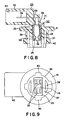
- Socket 21 includes core 22, outer shell 23, and inner cylinder 24.
- Outer shell 23 comprises connector receiver 42 with connector insertion opening 43 at one end thereof.
- Connector terminal 36 projects therein.
- Conductive terminal 32 is located within inner cylinder 24 and extends through terminal hole 28.
- Outer cylinder 37 surrounds inner cylinder 24 and circular cylinder 39 surrounds outer cylinder 37 and is of larger diameter so that it is radially spaced therefrom.
- Electrode terminals 35 are within inner cylinder 24 and terminate adjacent insertion opening 25.
- shield plate 33 overlies terminal hole 28.
- Outer cylinder 37, circular cylinder 39, flange 41, and engagement projections 40 make up core insertion portion 38.
- Conductive terminal 32 is provided with connector contacts 36 extending at right angles to the remainder of the terminal.
- Shield plates 33 have folded portions 44 and are integral with electrode terminals 35 and wall plates 34; the latter are adapted to be located adjacent the inner walls of inner cylinder 24.
- Cylinder 24 is provided with insets 30 into which folded portions 44 fit. Shield plates 33 overlie terminal holes 28 for protection.
- the ends of wall plates 34 rest in offset portions 27 on the inner wall of inner cylinder 24. Insertion legs 26 extend from inner cylinder 24 beyond insertion opening 25.
Landscapes
- Engineering & Computer Science (AREA)
- Manufacturing & Machinery (AREA)
- Connecting Device With Holders (AREA)
- Connector Housings Or Holding Contact Members (AREA)
- Manufacturing Of Electrical Connectors (AREA)
Claims (11)
- Buchse (1) zur Aufnahme und elektrischen Kontaktierung mit einer elektrischen Baueinheit und einem Steckverbinder, wobei die Buchse aufweist eine Einlage (22) mit einem Innenzylinder (24), der eine Zylinderachse hat und einen Innenraum mit einer Baueinheit - Einsetzöffnung (25) an seinem einen Ende definiert, einem elektrisch leitenden Anschluss (32) mit einem Baueinheitskontakt mit einem distalen Ende in dem Innenraum und benachbart zur Einsetzöffnung, und einen Verbinderkontakt (36), der sich durch ein Anschlussloch (28) von einem proximalen Ende des leitenden Anschlusses (32) entfernt zum distalen Ende aus dem Innenraum und eine Verbinderaufnahme (42) erstreckt, die einstückig mit einer Außenhülse (23) ausgebildet ist, die den Innenzylinder (24) umgibt und um die Einlage (22) ausgebildet ist, wobei der leitende Anschluss (32) einen Elektrodenanschluss, der für den Kontakt mit der Baueinheit ausgebildet ist, eine Wandplatte (34) in der Nähe der Innenseite einer Wand des Innenzylinders aufweist,
dadurch gekennzeichnet, dass der leitende Anschluss eine Abschirmplatte (33) in der Nähe des proximalen Endes aufweist und die vollständig über dem Anschlussloch (28) liegt. - Buchse nach Anspruch 1, wobei die Wand mit einem axial verkürzten Einsatz in der Nähe des Anschlussloches versehen ist, wobei die Abschirmplatte einen gebogenen Teil aufweist, der so ausgebildet ist, dass er in den Einsatz passt.
- Buchse nach Anspruch 1, wobei nebeneinander zwei der Innenzylinder mit zueinander parallelen Zylinderbuchsen vorgesehen sind, wobei sich zwischen diesen Innenzylindern parallel zu den Achsen eine Trennwand erstreckt.
- Buchse nach Anspruch 1, wobei der Querschnitt des Innenzylinders rechtwinkelig zur Zylinderachse rechteckig ist.
- Buchse nach Anspruch 1, wobei in der Wand des Innenzylinders entfernt von dem proximalen Ende ein versetzter Teil vorgesehen ist, wobei sich in dem versetzten Teil ein Ende der Wandplatte entfernt zur Abschirmplatte, befindet.
- Buchse nach Anspruch 1, wobei der Baueinheitkontakt ein paar Elektroden im Allgemeinen parallel zur Zylinderachse und sich von der Abschirmplatte zu einem Boden des Innenzylinders hin erstreckend aufweist, wobei die Elektroden zueinander vorgespannt sind, wodurch sie mit der Baueinheit einen elektrischen Kontakt bilden.
- Buchse nach Anspruch 1, wobei der leitende Anschluss aus einem einzigen Stück Metallblech besteht.
- Buchse nach Anspruch 3, wobei in jedem Innenraum ein versetzter Teil ist, wobei eine der Wandplatten in der Nähe der Innenseite einer entsprechenden einen der Wand, ein Ende jeder Wandplatte entfernt zu jeder Abschirmplatte, in einem entsprechenden einen der versetzen Teile hat.
- Buchse nach Anspruch 3, wobei jede Wand einen Einsetzschenkel hat, der sich parallel zur Zylinderachse in einer Richtung weg von einer entsprechenden einen der Abschirmplatten erstreckt, wodurch der Innenzylinder und der leitende Anschluss in einer Form zum Ausbilden der Aussenhülle fest und exakt positioniert werden können.
- Verfahren zur Herstellung der Buchse nach Anspruch 1, wobei die Aussenhülle eine Hüllenachse kürzer als die Zylinderachse hat, wobei das Verfahren aufweist,
Einsetzen des leitenden Anschlusses in den Innenzylinder und Führen des Verbinderkontaktes durch das Anschlussloch, um die Einlage zu bilden, so dass die Abschirmplatte über diesem Anschlussloch liegt,
Platzieren der Einlage in einer Form, die Hohlräume in Form der Verbinderaufnahme und der Aussenhülle hat, wobei die Form so ausgebildet ist, dass sie die Einlage während dem Formen aufnehmen und halten kann,
Einleiten von Formharz in die Hohlräume, wobei eine Oberfläche der Form an der Baueinheitöffnung anliegt, wodurch der leitende Anschluss gegenüber Berührung durch das Formharz geschützt ist. - Verfahren nach Anspruch 10, wobei der Innenzylinder mit Einsetzschenkeln versehen ist, die Form mit entsprechenden Aufnahmen für diese Schenkel versehen ist, die Schenkel in diese Aufnahmen nach dem Platzieren und vor dem Einleiten eingesetzt werden, wodurch die Einlage zuverlässig und exakt in der Form gehalten wird.
Applications Claiming Priority (2)
| Application Number | Priority Date | Filing Date | Title |
|---|---|---|---|
| JP10552096A JP3493889B2 (ja) | 1995-04-28 | 1996-04-25 | バルブソケットおよびその製造方法 |
| JP105520/96 | 1996-04-25 |
Publications (2)
| Publication Number | Publication Date |
|---|---|
| EP0803942A1 EP0803942A1 (de) | 1997-10-29 |
| EP0803942B1 true EP0803942B1 (de) | 2008-05-28 |
Family
ID=14409886
Family Applications (1)
| Application Number | Title | Priority Date | Filing Date |
|---|---|---|---|
| EP97106934A Expired - Lifetime EP0803942B1 (de) | 1996-04-25 | 1997-04-25 | Buchse zum Verbinden eines elektrischen Gerätes mit einem Steckverbinder |
Country Status (4)
| Country | Link |
|---|---|
| US (1) | US5846100A (de) |
| EP (1) | EP0803942B1 (de) |
| CN (1) | CN1139162C (de) |
| DE (1) | DE69738727D1 (de) |
Families Citing this family (16)
| Publication number | Priority date | Publication date | Assignee | Title |
|---|---|---|---|---|
| JP3447040B2 (ja) * | 1997-09-30 | 2003-09-16 | 矢崎総業株式会社 | バルブソケットの製造方法 |
| IT1303717B1 (it) * | 1998-11-06 | 2001-02-23 | Magneti Marelli Spa | Dispositivo di illuminazione, in particolare per veicoli. |
| US6302747B1 (en) * | 2000-05-02 | 2001-10-16 | Buehler Products, Inc. | Two-position (on-off) actuator with modular connector |
| US20070087637A1 (en) * | 2004-10-15 | 2007-04-19 | Zart Bryan J | Connector assembly for an implantable medical device and process for making |
| US7014510B2 (en) * | 2001-10-04 | 2006-03-21 | Guide Corporation | Wedge base sealed lamp socket |
| US7063575B2 (en) * | 2001-10-04 | 2006-06-20 | Guide Corporation | Terminal alignment features for bulb sockets |
| FR2850209B1 (fr) * | 2003-01-16 | 2007-09-14 | Cfca Finances | Connecteur electrique femelle |
| US7052301B2 (en) * | 2003-06-17 | 2006-05-30 | Christiana Industries, Inc. | Lamp socket |
| JP4292961B2 (ja) * | 2003-11-21 | 2009-07-08 | 住友電装株式会社 | バルブソケット |
| US20050163911A1 (en) * | 2004-01-28 | 2005-07-28 | Cargill, Inc. | Animal feed product containing crushed urea |
| DE102004007150A1 (de) * | 2004-02-12 | 2005-08-25 | Patent-Treuhand-Gesellschaft für elektrische Glühlampen mbH | Sockel für eine Scheinwerferlampe und Scheinwerferlampe |
| US20080032564A1 (en) * | 2006-08-01 | 2008-02-07 | Doman William J | Sealed Lamp Socket |
| US7479044B1 (en) | 2007-12-07 | 2009-01-20 | St. Clair Technologies, Inc. | Lamp socket |
| US20120170286A1 (en) * | 2010-12-10 | 2012-07-05 | Jack Bodem | Integral lamp assembly and method of construction thereof |
| JP7077928B2 (ja) * | 2018-12-06 | 2022-05-31 | 住友電装株式会社 | コネクタ及びその製造方法 |
| DE102021202196A1 (de) | 2021-03-08 | 2022-09-08 | Robert Bosch Gesellschaft mit beschränkter Haftung | Steckervorrichtung |
Family Cites Families (11)
| Publication number | Priority date | Publication date | Assignee | Title |
|---|---|---|---|---|
| DE1114764B (de) * | 1956-08-25 | 1961-10-12 | Hermann Schwarz K G | Schwenkbare Kappenverbindung fuer den Strebausbau |
| DE1147644B (de) * | 1959-12-28 | 1963-04-25 | Merten Geb | Geraetesteckdose |
| US4871331A (en) * | 1988-05-25 | 1989-10-03 | Yazaki Corporation | Bulb socket for wedged-base bulb |
| JPH0222951A (ja) * | 1988-07-12 | 1990-01-25 | Nec Field Service Ltd | 回線終端装置の診断方式 |
| JP2655921B2 (ja) * | 1990-01-16 | 1997-09-24 | 矢崎総業株式会社 | バルブソケットおよびその製造方法 |
| US5595513A (en) * | 1990-02-22 | 1997-01-21 | Yazaki Corporation | Bulb socket terminal |
| US5350322A (en) * | 1990-02-22 | 1994-09-27 | Yazaki Corporation | Bulb socket terminal |
| JP2581402B2 (ja) * | 1993-08-10 | 1997-02-12 | 日本電気株式会社 | 出力待ちレポートの削減方式 |
| JP3178185B2 (ja) * | 1993-09-07 | 2001-06-18 | 住友電装株式会社 | バルブソケット及びその製造方法 |
| US5509828A (en) * | 1993-11-25 | 1996-04-23 | Sumitomo Wiring Systems, Ltd. | L-shaped bulb socket |
| JP3337096B2 (ja) * | 1994-02-17 | 2002-10-21 | 住友電装株式会社 | バルブソケット |
-
1997
- 1997-04-14 US US08/839,448 patent/US5846100A/en not_active Expired - Lifetime
- 1997-04-25 CN CNB971097569A patent/CN1139162C/zh not_active Expired - Fee Related
- 1997-04-25 DE DE69738727T patent/DE69738727D1/de not_active Expired - Lifetime
- 1997-04-25 EP EP97106934A patent/EP0803942B1/de not_active Expired - Lifetime
Also Published As
| Publication number | Publication date |
|---|---|
| US5846100A (en) | 1998-12-08 |
| EP0803942A1 (de) | 1997-10-29 |
| DE69738727D1 (de) | 2008-07-10 |
| CN1170979A (zh) | 1998-01-21 |
| CN1139162C (zh) | 2004-02-18 |
Similar Documents
| Publication | Publication Date | Title |
|---|---|---|
| EP0803942B1 (de) | Buchse zum Verbinden eines elektrischen Gerätes mit einem Steckverbinder | |
| US6174203B1 (en) | Connector with housing insert molded to a magnetic element | |
| US6780068B2 (en) | Plug-in connector with a bushing | |
| JP2995679B2 (ja) | 電気コネクタ | |
| US4795352A (en) | Microcoaxial connector family | |
| US6059594A (en) | Sealed electrical connector | |
| EP0155181A2 (de) | Lampenanordnung | |
| EP1069654B1 (de) | Triaxialverbinder und Verfahren zum Zusammenbau eines solchen Steckverbinders | |
| JPH07282892A (ja) | コネクタ用防水栓 | |
| US20020049004A1 (en) | Cluster block connector | |
| EP0822626B1 (de) | Lampenfassung | |
| JPH09106851A (ja) | 防水コネクタ | |
| US6077087A (en) | Coaxial connector module with an overmolded ground contact | |
| US6361329B1 (en) | Header or receptacle for use in a power connector and process of assembling same | |
| EP0074159A2 (de) | Schutzhaube für eine schnellösbare elektrische Verbindung | |
| WO2001006598A1 (en) | Low profile electrical connectors for microphones | |
| JPH044385Y2 (de) | ||
| US6083054A (en) | Bulb socket and method for manufacturing the same | |
| EP0878875A3 (de) | Verbinder zur Montage auf Leiterplatten und in diesem verwendeter Kontakt | |
| JPH0317359B2 (de) | ||
| JPS62241277A (ja) | 防水コネクタ用ハウジング・アセンブリ | |
| JP2509623Y2 (ja) | 電気コネクタ | |
| JPS6330147Y2 (de) | ||
| JP2544850Y2 (ja) | 電球ソケット | |
| JPH0323674Y2 (de) |
Legal Events
| Date | Code | Title | Description |
|---|---|---|---|
| PUAI | Public reference made under article 153(3) epc to a published international application that has entered the european phase |
Free format text: ORIGINAL CODE: 0009012 |
|
| 17P | Request for examination filed |
Effective date: 19970425 |
|
| AK | Designated contracting states |
Kind code of ref document: A1 Designated state(s): DE FR GB |
|
| GRAP | Despatch of communication of intention to grant a patent |
Free format text: ORIGINAL CODE: EPIDOSNIGR1 |
|
| GRAS | Grant fee paid |
Free format text: ORIGINAL CODE: EPIDOSNIGR3 |
|
| GRAA | (expected) grant |
Free format text: ORIGINAL CODE: 0009210 |
|
| AK | Designated contracting states |
Kind code of ref document: B1 Designated state(s): DE FR GB |
|
| REG | Reference to a national code |
Ref country code: GB Ref legal event code: FG4D |
|
| REF | Corresponds to: |
Ref document number: 69738727 Country of ref document: DE Date of ref document: 20080710 Kind code of ref document: P |
|
| PLBE | No opposition filed within time limit |
Free format text: ORIGINAL CODE: 0009261 |
|
| STAA | Information on the status of an ep patent application or granted ep patent |
Free format text: STATUS: NO OPPOSITION FILED WITHIN TIME LIMIT |
|
| 26N | No opposition filed |
Effective date: 20090303 |
|
| PGFP | Annual fee paid to national office [announced via postgrant information from national office to epo] |
Ref country code: GB Payment date: 20100325 Year of fee payment: 14 |
|
| PGFP | Annual fee paid to national office [announced via postgrant information from national office to epo] |
Ref country code: FR Payment date: 20100521 Year of fee payment: 14 |
|
| PGFP | Annual fee paid to national office [announced via postgrant information from national office to epo] |
Ref country code: DE Payment date: 20100430 Year of fee payment: 14 |
|
| REG | Reference to a national code |
Ref country code: DE Ref legal event code: R119 Ref document number: 69738727 Country of ref document: DE |
|
| REG | Reference to a national code |
Ref country code: DE Ref legal event code: R119 Ref document number: 69738727 Country of ref document: DE |
|
| GBPC | Gb: european patent ceased through non-payment of renewal fee |
Effective date: 20110425 |
|
| REG | Reference to a national code |
Ref country code: FR Ref legal event code: ST Effective date: 20111230 |
|
| PG25 | Lapsed in a contracting state [announced via postgrant information from national office to epo] |
Ref country code: FR Free format text: LAPSE BECAUSE OF NON-PAYMENT OF DUE FEES Effective date: 20110502 |
|
| PG25 | Lapsed in a contracting state [announced via postgrant information from national office to epo] |
Ref country code: GB Free format text: LAPSE BECAUSE OF NON-PAYMENT OF DUE FEES Effective date: 20110425 |
|
| PG25 | Lapsed in a contracting state [announced via postgrant information from national office to epo] |
Ref country code: DE Free format text: LAPSE BECAUSE OF NON-PAYMENT OF DUE FEES Effective date: 20111031 |