EP0803942A1 - Buchse zum Verbinden eines elektrischen Gerätes mit einem Steckverbinder - Google Patents
Buchse zum Verbinden eines elektrischen Gerätes mit einem Steckverbinder Download PDFInfo
- Publication number
- EP0803942A1 EP0803942A1 EP97106934A EP97106934A EP0803942A1 EP 0803942 A1 EP0803942 A1 EP 0803942A1 EP 97106934 A EP97106934 A EP 97106934A EP 97106934 A EP97106934 A EP 97106934A EP 0803942 A1 EP0803942 A1 EP 0803942A1
- Authority
- EP
- European Patent Office
- Prior art keywords
- socket
- core
- cylinder
- adjacent
- mold
- Prior art date
- Legal status (The legal status is an assumption and is not a legal conclusion. Google has not performed a legal analysis and makes no representation as to the accuracy of the status listed.)
- Granted
Links
Images


Classifications
-
- H—ELECTRICITY
- H01—ELECTRIC ELEMENTS
- H01R—ELECTRICALLY-CONDUCTIVE CONNECTIONS; STRUCTURAL ASSOCIATIONS OF A PLURALITY OF MUTUALLY-INSULATED ELECTRICAL CONNECTING ELEMENTS; COUPLING DEVICES; CURRENT COLLECTORS
- H01R43/00—Apparatus or processes specially adapted for manufacturing, assembling, maintaining, or repairing of line connectors or current collectors or for joining electric conductors
- H01R43/20—Apparatus or processes specially adapted for manufacturing, assembling, maintaining, or repairing of line connectors or current collectors or for joining electric conductors for assembling or disassembling contact members with insulating base, case or sleeve
- H01R43/24—Assembling by moulding on contact members
-
- H—ELECTRICITY
- H01—ELECTRIC ELEMENTS
- H01R—ELECTRICALLY-CONDUCTIVE CONNECTIONS; STRUCTURAL ASSOCIATIONS OF A PLURALITY OF MUTUALLY-INSULATED ELECTRICAL CONNECTING ELEMENTS; COUPLING DEVICES; CURRENT COLLECTORS
- H01R33/00—Coupling devices specially adapted for supporting apparatus and having one part acting as a holder providing support and electrical connection via a counterpart which is structurally associated with the apparatus, e.g. lamp holders; Separate parts thereof
- H01R33/05—Two-pole devices
- H01R33/06—Two-pole devices with two current-carrying pins, blades or analogous contacts, having their axes parallel to each other
-
- H—ELECTRICITY
- H01—ELECTRIC ELEMENTS
- H01R—ELECTRICALLY-CONDUCTIVE CONNECTIONS; STRUCTURAL ASSOCIATIONS OF A PLURALITY OF MUTUALLY-INSULATED ELECTRICAL CONNECTING ELEMENTS; COUPLING DEVICES; CURRENT COLLECTORS
- H01R2201/00—Connectors or connections adapted for particular applications
- H01R2201/08—Connectors or connections adapted for particular applications for halogen lamps
Definitions
- the present Invention is directed to a device for receiving an electrical unit at one end and a connector at the other.
- the Invention will be described primarily with reference to a bulb, especially one with a wedge-shaped base, but it is understood that any suitable electrical unit can be used in conjunction therewith.
- the present Invention is directed to a socket which is adapted to receive and make electrical contact with a light bulb and a connector. It is composed of a core, which includes a hollow inner cylinder defining an interior space. A conductive terminal is located in the space extending from a bulb insertion opening at one end, through a terminal hole in the inner cylinder, into a connector receiver. The distal end of the conductive terminal is located in the interior space, adjacent the bulb insertion opening. The other end of the terminal is protected by the connector receiver; the connector can be inserted therein in order to make suitable contact therewith.
- the conductive terminal includes a pair of electrode terminals which are spring loaded toward each other in order to make good electrical contact with the bulb.
- a shield plate is provided which overlies the terminal hole after the conductive terminal has been fully inserted. This prevents entry of resin during the insert molding process.
- the wall is axially shortened at the end adjacent the shield plate. This provides room for a folded portion at the edge of the shield plate to fit without lengthening the inner cylinder.
- the walls are extended in the direction away from the shield plate to form insertion legs which are substantially parallel to the axes. These can be inserted into corresponding grooves in the mold in order to accurately and reliably position the inner cylinder for molding of the surrounding portions of the socket.
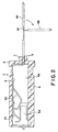
- socket 1 comprises core 2, outer cylindrical shell 3, and connector receiver 16.
- Core 2 includes conductive terminal 6 which extends through terminal hole 8 and into connector receiver 16.
- Core 2 is provided with bulb insertion opening 5 at the end opposite terminal hole 8.
- Conductive terminal 6 comprises wall plate 6A, pressing piece 6B, long elastic piece 6C, and short elastic piece 6D.
- Connector contact 6E extends into connector receiver 16 and is provided with bending section 6F which is more pliable than the remaining sections of conductive terminal 6.
- Outer cylinder 10 surrounds inner cylinder 4 and is provided with overflow groove 12 adjacent insertion opening 5.
- the overflow groove is intended to receive any resin which would otherwise enter the space within inner cylinder 4 and thus impair the integrity of the connection between conductive terminal 6 and the bulb being inserted (not shown).
- Core 2 is provided, at the end remote from opening 5, with projection 7 and projecting rim 9 which serve to lock core 2 within outer cylinder 10.
- outer shell 13 is provided with flange 15 and four engagement projections 14.
- the socket of the present Invention is best manufactured by insertion molding. As is best shown in Figure 7, core 2 is placed in molds K1, K2, and K3. The molds have cavities such that they are adapted to produce outer shell 3, outer cylinder 10, and connector insertion portion 16. Mold K1 is provided with molding surface 18 and projection rim 19. The former is in contact with insertion opening 5 of core 2 and effectively prevents resin from contacting conductive terminal 6. In addition, projection rim 19 forms overflow groove 12 (see Figure 1) to receive excess resin.
- Conductive terminal 6 is inserted through insertion opening 5 into inner cylinder 4.
- Connector terminal 6E and bending portion 6F are as shown in solid lines in Figure 2. This makes it easy to pass these portions of conductive terminal 6 through terminal hole 8. Thereafter, connector terminal 6E is bent into the position shown in broken lines; the pliability of bending portion 6F assists in carrying out this step.
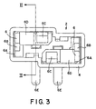
- Socket 21 includes core 22, outer shell 23, and inner cylinder 24.
- Outer shell 23 comprises connector receiver 42 with connector insertion opening 43 at one end thereof.
- Connector terminal 36 projects therein.
- Conductive terminal 32 is located within inner cylinder 24 and extends through terminal hole 28.
- Outer cylinder 37 surrounds inner cylinder 24 and circular cylinder 39 surrounds outer cylinder 37 and is of larger diameter so that it is radially spaced therefrom.
- Electrode terminals 35 are within inner cylinder 24 and terminate adjacent insertion opening 25.
- shield plate 33 overlies terminal hole 28.
- Outer cylinder 37, circular cylinder 39, flange 41, and engagement projections 40 make up core insertion portion 38.
- Conductive terminal 32 is provided with connector contacts 36 extending at right angles to the remainder of the terminal.
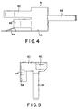
- Shield plates 33 have folded portions 44 and are integral with electrode terminals 35 and wall plates 34; the latter are adapted to be located adjacent the inner walls of inner cylinder 24.
- Cylinder 24 is provided with insets 30 into which folded portions 44 fit. Shield plates 33 overlie terminal holes 28 for protection.
- the ends of wall plates 34 rest in offset portions 27 on the inner wall of inner cylinder 24. Insertion legs 26 extend from inner cylinder 24 beyond insertion opening 25.
- core 22 is assembled by inserting conductive terminal 32 into cylinder 24 through terminal hole 28.
- Folded edge 44 fits into inset 30 so that shield plate 33 overlies terminal hole 28.
- the ends of wall plate 34 rest on offset portions 27.
- this embodiment of the Invention provides shield plates which protect the terminal hole and comprises electrode terminals 35 which are spring biased toward each other to securely grip the electrical bulb being inserted.
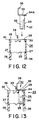
- insertion legs 26 are introduced into insertion cavity 45 in mold K11 and thereby secure core 22 and electrode terminals 35 therein. Thereafter, molds K12 and K13 are moved into place as shown. Shield plates 33 overlie and protect electrode terminals 35 from contamination by the molding resin.
- inner cylinder 24 is provided with undercuts 51.
- One edge and the folded portion of shield plate 33 are fitted into undercuts 51, thereby securing shield plate 33 to terminal hole 28.
- mold K11 is provided with cylinder mount 53.
- Inner cylinder 24 is inserted therein.
- conductive terminal 32 is introduced into inner cylinder 24.
- cylinder mount 53 is undercut adjacent its floor.
- Complementary projection 54 is formed on inner cylinder 24.
- projection 54 enters the undercut portion of cylinder mount 53, thereby locking cylinder 24 in place. In this way, insertion molding can be readily carried out without the danger of displacing or over-turning inner cylinder 24.
Landscapes
- Engineering & Computer Science (AREA)
- Manufacturing & Machinery (AREA)
- Connecting Device With Holders (AREA)
- Connector Housings Or Holding Contact Members (AREA)
- Manufacturing Of Electrical Connectors (AREA)
Applications Claiming Priority (2)
| Application Number | Priority Date | Filing Date | Title |
|---|---|---|---|
| JP105520/96 | 1996-04-25 | ||
| JP10552096A JP3493889B2 (ja) | 1995-04-28 | 1996-04-25 | バルブソケットおよびその製造方法 |
Publications (2)
| Publication Number | Publication Date |
|---|---|
| EP0803942A1 true EP0803942A1 (de) | 1997-10-29 |
| EP0803942B1 EP0803942B1 (de) | 2008-05-28 |
Family
ID=14409886
Family Applications (1)
| Application Number | Title | Priority Date | Filing Date |
|---|---|---|---|
| EP97106934A Expired - Lifetime EP0803942B1 (de) | 1996-04-25 | 1997-04-25 | Buchse zum Verbinden eines elektrischen Gerätes mit einem Steckverbinder |
Country Status (4)
| Country | Link |
|---|---|
| US (1) | US5846100A (de) |
| EP (1) | EP0803942B1 (de) |
| CN (1) | CN1139162C (de) |
| DE (1) | DE69738727D1 (de) |
Cited By (3)
| Publication number | Priority date | Publication date | Assignee | Title |
|---|---|---|---|---|
| EP0999617A1 (de) * | 1998-11-06 | 2000-05-10 | Automotive Lighting Italia Spa | Beleuchtungseinrichtung, insbesondere für Fahrzeuge |
| DE19844633C2 (de) * | 1997-09-30 | 2001-03-01 | Yazaki Corp | Glühbirnenfassung und Verfahren zur Herstellung derselben |
| EP1439613A1 (de) * | 2003-01-16 | 2004-07-21 | C.F.C.A. Finances | Weiblicher elektrischer Steckverbinder |
Families Citing this family (13)
| Publication number | Priority date | Publication date | Assignee | Title |
|---|---|---|---|---|
| US6302747B1 (en) * | 2000-05-02 | 2001-10-16 | Buehler Products, Inc. | Two-position (on-off) actuator with modular connector |
| US20070087637A1 (en) * | 2004-10-15 | 2007-04-19 | Zart Bryan J | Connector assembly for an implantable medical device and process for making |
| US7063575B2 (en) | 2001-10-04 | 2006-06-20 | Guide Corporation | Terminal alignment features for bulb sockets |
| US7014510B2 (en) * | 2001-10-04 | 2006-03-21 | Guide Corporation | Wedge base sealed lamp socket |
| US7052301B2 (en) * | 2003-06-17 | 2006-05-30 | Christiana Industries, Inc. | Lamp socket |
| JP4292961B2 (ja) * | 2003-11-21 | 2009-07-08 | 住友電装株式会社 | バルブソケット |
| US20050163911A1 (en) * | 2004-01-28 | 2005-07-28 | Cargill, Inc. | Animal feed product containing crushed urea |
| DE102004007150A1 (de) * | 2004-02-12 | 2005-08-25 | Patent-Treuhand-Gesellschaft für elektrische Glühlampen mbH | Sockel für eine Scheinwerferlampe und Scheinwerferlampe |
| US20080032564A1 (en) * | 2006-08-01 | 2008-02-07 | Doman William J | Sealed Lamp Socket |
| US7479044B1 (en) | 2007-12-07 | 2009-01-20 | St. Clair Technologies, Inc. | Lamp socket |
| BR112013014469A2 (pt) * | 2010-12-10 | 2016-09-13 | Federal Mogul Ignition Co | montagem de lâmpada integral e método de contrução da mesma |
| JP7077928B2 (ja) * | 2018-12-06 | 2022-05-31 | 住友電装株式会社 | コネクタ及びその製造方法 |
| DE102021202196A1 (de) | 2021-03-08 | 2022-09-08 | Robert Bosch Gesellschaft mit beschränkter Haftung | Steckervorrichtung |
Citations (3)
| Publication number | Priority date | Publication date | Assignee | Title |
|---|---|---|---|---|
| DE1147644B (de) * | 1959-12-28 | 1963-04-25 | Merten Geb | Geraetesteckdose |
| US5080615A (en) * | 1990-01-16 | 1992-01-14 | Yazaki Corporation | Bulb socket and method of manufacturing the same |
| EP0642196A2 (de) * | 1993-09-07 | 1995-03-08 | Sumitomo Wiring Systems, Ltd. | Lampenfassung und Verfahren zu ihrer Herstellung |
Family Cites Families (8)
| Publication number | Priority date | Publication date | Assignee | Title |
|---|---|---|---|---|
| DE1114764B (de) * | 1956-08-25 | 1961-10-12 | Hermann Schwarz K G | Schwenkbare Kappenverbindung fuer den Strebausbau |
| US4871331A (en) * | 1988-05-25 | 1989-10-03 | Yazaki Corporation | Bulb socket for wedged-base bulb |
| JPH0222951A (ja) * | 1988-07-12 | 1990-01-25 | Nec Field Service Ltd | 回線終端装置の診断方式 |
| US5595513A (en) * | 1990-02-22 | 1997-01-21 | Yazaki Corporation | Bulb socket terminal |
| US5350322A (en) * | 1990-02-22 | 1994-09-27 | Yazaki Corporation | Bulb socket terminal |
| JP2581402B2 (ja) * | 1993-08-10 | 1997-02-12 | 日本電気株式会社 | 出力待ちレポートの削減方式 |
| US5509828A (en) * | 1993-11-25 | 1996-04-23 | Sumitomo Wiring Systems, Ltd. | L-shaped bulb socket |
| JP3337096B2 (ja) * | 1994-02-17 | 2002-10-21 | 住友電装株式会社 | バルブソケット |
-
1997
- 1997-04-14 US US08/839,448 patent/US5846100A/en not_active Expired - Lifetime
- 1997-04-25 CN CNB971097569A patent/CN1139162C/zh not_active Expired - Fee Related
- 1997-04-25 DE DE69738727T patent/DE69738727D1/de not_active Expired - Lifetime
- 1997-04-25 EP EP97106934A patent/EP0803942B1/de not_active Expired - Lifetime
Patent Citations (3)
| Publication number | Priority date | Publication date | Assignee | Title |
|---|---|---|---|---|
| DE1147644B (de) * | 1959-12-28 | 1963-04-25 | Merten Geb | Geraetesteckdose |
| US5080615A (en) * | 1990-01-16 | 1992-01-14 | Yazaki Corporation | Bulb socket and method of manufacturing the same |
| EP0642196A2 (de) * | 1993-09-07 | 1995-03-08 | Sumitomo Wiring Systems, Ltd. | Lampenfassung und Verfahren zu ihrer Herstellung |
Cited By (4)
| Publication number | Priority date | Publication date | Assignee | Title |
|---|---|---|---|---|
| DE19844633C2 (de) * | 1997-09-30 | 2001-03-01 | Yazaki Corp | Glühbirnenfassung und Verfahren zur Herstellung derselben |
| EP0999617A1 (de) * | 1998-11-06 | 2000-05-10 | Automotive Lighting Italia Spa | Beleuchtungseinrichtung, insbesondere für Fahrzeuge |
| EP1439613A1 (de) * | 2003-01-16 | 2004-07-21 | C.F.C.A. Finances | Weiblicher elektrischer Steckverbinder |
| FR2850209A1 (fr) * | 2003-01-16 | 2004-07-23 | Cfca Finances | Connecteur electrique femelle |
Also Published As
| Publication number | Publication date |
|---|---|
| US5846100A (en) | 1998-12-08 |
| EP0803942B1 (de) | 2008-05-28 |
| CN1170979A (zh) | 1998-01-21 |
| CN1139162C (zh) | 2004-02-18 |
| DE69738727D1 (de) | 2008-07-10 |
Similar Documents
| Publication | Publication Date | Title |
|---|---|---|
| US5846100A (en) | Socket for connection of an electrical unit with a connector | |
| JP2995679B2 (ja) | 電気コネクタ | |
| JP2863083B2 (ja) | コネクタ用防水栓 | |
| EP0822626B1 (de) | Lampenfassung | |
| US4682838A (en) | Multipolar plug | |
| US6409548B1 (en) | Microelectronic connector with open-cavity insert | |
| US5507670A (en) | Bulb socket | |
| EP0709936A2 (de) | Lampenfassung | |
| US6083054A (en) | Bulb socket and method for manufacturing the same | |
| EP1148600A1 (de) | Adapter für die elektrische Verbindung zwischen einem Stecker und einer Buchse | |
| JPH044385Y2 (de) | ||
| EP1109261A3 (de) | Elektrischer Stecker mit Verbinderpositioniermittel | |
| CN217848378U (zh) | 连接器模块和连接器 | |
| JPS645831Y2 (de) | ||
| JPH0668328U (ja) | コネクタハウジング | |
| JPS6231985Y2 (de) | ||
| JPS6231986Y2 (de) | ||
| JP2000021519A (ja) | ピン型ac電源用プラグ | |
| JP2509623Y2 (ja) | 電気コネクタ | |
| JPS6330147Y2 (de) | ||
| JPS6327428Y2 (de) | ||
| JPS6224952Y2 (de) | ||
| JP2544850Y2 (ja) | 電球ソケット | |
| JPH0222955Y2 (de) | ||
| JPH0117091Y2 (de) |
Legal Events
| Date | Code | Title | Description |
|---|---|---|---|
| PUAI | Public reference made under article 153(3) epc to a published international application that has entered the european phase |
Free format text: ORIGINAL CODE: 0009012 |
|
| 17P | Request for examination filed |
Effective date: 19970425 |
|
| AK | Designated contracting states |
Kind code of ref document: A1 Designated state(s): DE FR GB |
|
| GRAP | Despatch of communication of intention to grant a patent |
Free format text: ORIGINAL CODE: EPIDOSNIGR1 |
|
| GRAS | Grant fee paid |
Free format text: ORIGINAL CODE: EPIDOSNIGR3 |
|
| GRAA | (expected) grant |
Free format text: ORIGINAL CODE: 0009210 |
|
| AK | Designated contracting states |
Kind code of ref document: B1 Designated state(s): DE FR GB |
|
| REG | Reference to a national code |
Ref country code: GB Ref legal event code: FG4D |
|
| REF | Corresponds to: |
Ref document number: 69738727 Country of ref document: DE Date of ref document: 20080710 Kind code of ref document: P |
|
| PLBE | No opposition filed within time limit |
Free format text: ORIGINAL CODE: 0009261 |
|
| STAA | Information on the status of an ep patent application or granted ep patent |
Free format text: STATUS: NO OPPOSITION FILED WITHIN TIME LIMIT |
|
| 26N | No opposition filed |
Effective date: 20090303 |
|
| PGFP | Annual fee paid to national office [announced via postgrant information from national office to epo] |
Ref country code: GB Payment date: 20100325 Year of fee payment: 14 |
|
| PGFP | Annual fee paid to national office [announced via postgrant information from national office to epo] |
Ref country code: FR Payment date: 20100521 Year of fee payment: 14 |
|
| PGFP | Annual fee paid to national office [announced via postgrant information from national office to epo] |
Ref country code: DE Payment date: 20100430 Year of fee payment: 14 |
|
| REG | Reference to a national code |
Ref country code: DE Ref legal event code: R119 Ref document number: 69738727 Country of ref document: DE |
|
| REG | Reference to a national code |
Ref country code: DE Ref legal event code: R119 Ref document number: 69738727 Country of ref document: DE |
|
| GBPC | Gb: european patent ceased through non-payment of renewal fee |
Effective date: 20110425 |
|
| REG | Reference to a national code |
Ref country code: FR Ref legal event code: ST Effective date: 20111230 |
|
| PG25 | Lapsed in a contracting state [announced via postgrant information from national office to epo] |
Ref country code: FR Free format text: LAPSE BECAUSE OF NON-PAYMENT OF DUE FEES Effective date: 20110502 |
|
| PG25 | Lapsed in a contracting state [announced via postgrant information from national office to epo] |
Ref country code: GB Free format text: LAPSE BECAUSE OF NON-PAYMENT OF DUE FEES Effective date: 20110425 |
|
| PG25 | Lapsed in a contracting state [announced via postgrant information from national office to epo] |
Ref country code: DE Free format text: LAPSE BECAUSE OF NON-PAYMENT OF DUE FEES Effective date: 20111031 |