EP0803888B1 - Trennschalter - Google Patents
Trennschalter Download PDFInfo
- Publication number
- EP0803888B1 EP0803888B1 EP97810153A EP97810153A EP0803888B1 EP 0803888 B1 EP0803888 B1 EP 0803888B1 EP 97810153 A EP97810153 A EP 97810153A EP 97810153 A EP97810153 A EP 97810153A EP 0803888 B1 EP0803888 B1 EP 0803888B1
- Authority
- EP
- European Patent Office
- Prior art keywords
- isolating switch
- switching
- drive shaft
- guide
- cam
- Prior art date
- Legal status (The legal status is an assumption and is not a legal conclusion. Google has not performed a legal analysis and makes no representation as to the accuracy of the status listed.)
- Expired - Lifetime
Links
- 230000033001 locomotion Effects 0.000 description 6
- 230000008878 coupling Effects 0.000 description 4
- 238000010168 coupling process Methods 0.000 description 4
- 238000005859 coupling reaction Methods 0.000 description 4
- 230000005540 biological transmission Effects 0.000 description 3
- 239000012212 insulator Substances 0.000 description 3
- 241001136792 Alle Species 0.000 description 2
- 239000002184 metal Substances 0.000 description 2
Images


Classifications
-
- H—ELECTRICITY
- H01—ELECTRIC ELEMENTS
- H01H—ELECTRIC SWITCHES; RELAYS; SELECTORS; EMERGENCY PROTECTIVE DEVICES
- H01H3/00—Mechanisms for operating contacts
- H01H3/32—Driving mechanisms, i.e. for transmitting driving force to the contacts
- H01H3/42—Driving mechanisms, i.e. for transmitting driving force to the contacts using cam or eccentric
-
- H—ELECTRICITY
- H01—ELECTRIC ELEMENTS
- H01H—ELECTRIC SWITCHES; RELAYS; SELECTORS; EMERGENCY PROTECTIVE DEVICES
- H01H31/00—Air-break switches for high tension without arc-extinguishing or arc-preventing means
- H01H31/26—Air-break switches for high tension without arc-extinguishing or arc-preventing means with movable contact that remains electrically connected to one line in open position of switch
- H01H31/32—Air-break switches for high tension without arc-extinguishing or arc-preventing means with movable contact that remains electrically connected to one line in open position of switch with rectilinearly-movable contact
-
- H—ELECTRICITY
- H02—GENERATION; CONVERSION OR DISTRIBUTION OF ELECTRIC POWER
- H02B—BOARDS, SUBSTATIONS OR SWITCHING ARRANGEMENTS FOR THE SUPPLY OR DISTRIBUTION OF ELECTRIC POWER
- H02B13/00—Arrangement of switchgear in which switches are enclosed in, or structurally associated with, a casing, e.g. cubicle
- H02B13/02—Arrangement of switchgear in which switches are enclosed in, or structurally associated with, a casing, e.g. cubicle with metal casing
- H02B13/035—Gas-insulated switchgear
-
- H—ELECTRICITY
- H01—ELECTRIC ELEMENTS
- H01H—ELECTRIC SWITCHES; RELAYS; SELECTORS; EMERGENCY PROTECTIVE DEVICES
- H01H31/00—Air-break switches for high tension without arc-extinguishing or arc-preventing means
- H01H31/003—Earthing switches
Definitions
- a disconnector is assumed after common preamble of claim 1 and claim 4.
- Such a circuit breaker is advantageously used as a multiple separator in a metal-encapsulated gas-insulated switchgear used and can be used as needed between two of several arbitrary system components Make connections or disconnect these connections, such as for example between a circuit breaker and any two Busbars, between the two busbars or between the circuit breaker and an earth contact.
- a circuit breaker described in this patent application has an earthed isolator housing filled with an insulating gas and two axially symmetrical arranged in the isolator housing trained switching points, each with a fixed and a switching piece movable along the switching point axis and a drive shaft guided into the isolator housing and a Transmission, which force from the drive shaft to the movable Switch piece can transmit.
- the gearbox contains one of the Drive shaft rotated crank arm on which two coupling rods are articulated.
- Coupling rods act on movable contacts of the switching points, which slidably guided in the direction of the switching point axis are.
- the invention lies based on the task of a disconnector of the aforementioned Specify type that is characterized by a compact design and at the same time a very precise control in a simple manner of the individual switching points.
- the disconnector according to the invention is characterized in that that it is designed to be extremely space-saving. On the one hand, this is due to the fact that between the drive shaft and movable Switching gear unit supplied by the drive shaft Driving force directly converts into forces towards the Switching point axes act, and secondly with the transmission Coupling rods between the drive shaft and the movable Switch pieces are eliminated.
- the gearbox only contains the Movable switching elements integrated control discs and on the Drive shaft attached levers. Such control discs claim little space and at the same time carry one in a space-saving manner Guide curve or two guide curves, which are those of the levers force given as a function of the angular position of the drive shaft forward controlled to the assigned moving contact.
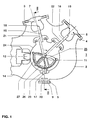
- the isolating switch shown in FIGS. 1 and 2 and identified by the reference number 1 has a substantially tubular metal housing 2 filled with insulating gas, such as SF 6 of a few bar pressure.
- the disconnector switch housing 2 is at earth potential and has four openings on its jacket surface, which are each delimited by one of four tubular flange attachments 3, 4, 5 and 6.
- On the flange shoulder 3 or 4 is supported with the aid of an insulator (not designated) an electrically insulated fixed contact 7 or 8 with respect to the isolating switch housing 2.
- the flange extension 5, on the other hand, carries a fixed contact piece 9 connected to the disconnector housing 2 in an electrically conductive manner.
- the flange extension 6 carries a metal mounting cover 10 through which a drive shaft 11 is guided in a gas-tight manner into the interior of the disconnector housing 2.
- the drive shaft 11 is guided in a hollow insulator 12 fastened to the assembly cover 10.
- a fifth opening of the disconnector switch housing 2, which is not designated, is delimited by a flange attachment 14 carrying an electrical connection 13 in an electrically insulating manner.
- the reference numerals 15, 16 and 17 are essentially pen-shaped trained, movable contact pieces called.
- the movable contact piece 15 and the fixed contact piece 7 form a switching point 18, the movable contact piece 16 and the fixed contact piece 8 a switching point 19 and movable contact 17 and the fixed contact 9 a Switching point 20.
- the three switching points 18, 19 and 20 are in essentially axially symmetrical.
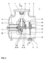
- the movable ones Switch pieces 15, 16 and 17 are over not designated Sliding contacts (Fig.2) and a shield 24 with the power connector 13 electrically connected.
- the switching point axes 21 and 22 are perpendicular to the axis of the drive shaft 11 and are against each other at an angle of typically 45 ° inclined up to 180 °.
- At the fixed contact piece 7 or 8 can a busbar connected in an electrically conductive manner his.
- the switching points 18 and 19 then each act as busbar disconnectors. Since the fixed contact 9 is grounded, the switching point 23 acts as an earth electrode.
- the power connector 13 is in the generally with the busbar-side outlet of a Circuit breaker connected.
- the two switching points 18 and 19 can also be in be arranged a line outlet.
- the gear 25 has one for each of the switching points 18, 19 and 20 with the assigned movable contact piece 15, 16, 17 firmly connected, aligned and displaceable transversely to the axis of the drive shaft 11 Control disc 26, 27, 28 and at least two axially offset against each other, attached to the drive shaft 11 and with the control disk 26 or 27 or 28 cooperating levers 29, 30 or 31, 32 or 33, 34.
- the structure of a typical control disc, for example the Control disc 26 can be seen from Figures 3 to 6.
- the Control disc has a guide curves 35 and on the front on the back a mirror image Lead curve 36 on.
- the guide curve 35 takes when turning the Drive shaft 11 a guide part 290 and attached to the lever 29 the guide curve 36 is a guide part 300 fastened to the lever 30 on.
- Each guide curve 35 or 36 has a section 39 or 41 and one following this section Section 40 or 42 and one between the two sections 39 and 41 or 40 and 42 provided stop 43 or 44 on.
- the control disk has a direction of the switching point axis 21 elongated slot 45.
- the drive shaft is passed through this slot and leads the control disc 26 in Direction of the switching point axis 21. With the switching point closed 18 strikes the elongated hole 45 with its lower end (FIGS. 3 and 4) and with its switch point open arranged upper end ( Figures 5 and 6) on the drive shaft 11 on.
- the circuit breaker works as follows: In Switch-on state of switching point 18 (FIGS. 3 and 4) the moving contact 15 contacts the fixed one Contact piece 7. Fixed with the movable contact piece 15 connected control disc 26 is guided upwards and strikes the lower end of the elongated hole 45 on the drive shaft 11. The guide member 290 attached to lever 29 contacts the section 40 and thus ensures that when the drive shaft 11 is at rest Control disc 26 and thus also the movable contact piece 15 are fixed. At the same time contacted the attached to the lever 30 Guide part 300 section 42 and thus also sets that movable contact piece 15 fixed.
- the drive shaft 11 In Turned clockwise (see also Fig. 1).
- the guide parts 290 and 300 are initially along the curve sections 40 and 42 out. These sections are essentially as Arcs formed. The center of the assigned circles is on the axis of the drive shaft 11.
- the guide member 290 exits section 40.
- the guide member 300 strikes the Stop 44 and now the control disc 26 and that movable contact piece 15 moved down until the Drive shaft 11 reaches the upper end of the elongated hole 45 (figures 5 and 6). Switching point 18 is then open.
- Guide part 300 in the form of an arc Section 41 now moves and contacts the guide member 290 also formed as a circular section 39 of the Guide curve 35.
- the movable contact piece 15 is in the Switch-off position fixed.
- the drive shaft 11 can also run counterclockwise be operated.
- the guide part 300 then opens from below the stop 44 and then leads the control disc 26 and thus also the movable contact piece 15 from the switch-off the switch-on position. In a corresponding way, this then beats Guide part 290 from above on the stop 43 and leads then the control disc 26 and thus also the movable Switch piece 15 from the on to the off position.
- a particularly small overall depth in the axial direction is reached when the guide curves 35, 36 each as a groove in the Control disc are molded.
- the guide parts 290, 300 can then be designed as cams engaging in the grooves.
- the two guide curves 35, 36 are on opposite sides Arranged sides of the control disc 26. But you can too in each case on one of two with the movable contact piece 15 connected control discs can be arranged. In this case only one arranged between these two control disks and the lever containing two guide parts 290, 300 is required.
- the guide curve 46 points in the embodiment according to FIG two arcuate sections 48, 49 and two stop points arranged between these two sections 50, 51 on. These stop points are inclined to the switching point axis 21 arranged curve sections formed.
- Such a guide curve can be used for movement sequences for the Realize moving contact piece 15, as for one in one Double busbar system provided busbar disconnectors are typical.
- the guide curve 46 can, depending on the requirements of the movement sequence of the movable contact piece modified differently be trained.
- the moving contact is part of a Erders, it is recommended that the one shown in Fig. 9 Embodiment of the guide curve 46 to use.
- the curve-shaped section comprises the guide curve 49 has an angular range of approx. 270 ° and goes to both of them Ends in curve sections 52 and 53 respectively, which essentially are aligned radially and at an angle to the switching point axis 23 are arranged.
- the curve sections 52, 53 act as stops and move the control disc 28 and thus the movable Switch 17 in the switch-on or switch-off direction.
- Guide curve 46 is the control disc 28 and thus that movable contact piece 17 held in the switch-on position.
Landscapes
- Engineering & Computer Science (AREA)
- Power Engineering (AREA)
- Driving Mechanisms And Operating Circuits Of Arc-Extinguishing High-Tension Switches (AREA)
- Control Of Transmission Device (AREA)
- Gear-Shifting Mechanisms (AREA)
- Arrangement Or Mounting Of Control Devices For Change-Speed Gearing (AREA)
- Mechanisms For Operating Contacts (AREA)
Description
- Fig.1
- eine Aufsicht auf einen überwiegend quer zur Rohrachse längs einer Linie I-I (Fig.2) geführten Schnitt durch ein im wesentlichen rohrförmig ausgebildetes Gehäuse einer ersten Ausführungsform des Trennschalters nach der Erfindung,
- Fig.2
- eine Aufsicht auf einen längs einer Linie II-II axial geführten Schnitt durch den Trennschalter nach Fig.1,
- Fig.3
- eine Aufsicht auf eine im Trennschalter gemäss Fig.1 vorgesehene Steuerscheibe bei geschlossener Schaltstelle,
- Fig.4
- eine Aufsicht auf die Steuerscheibe gemäss Fig.3, bei der alle Teile auf der Frontseite der Steuerscheibe entfernt und alle auf der Rückseite der Steuerscheibe vorgesehenen Teile gestrichelt dargestellt sind,
- Fig.5
- eine Aufsicht auf die Steuerscheibe gemäss Fig.3 bei geöffneter Schaltstelle,
- Fig.6
- eine Aufsicht auf die entsprechend Fig.4 dargestellte Steuerscheibe bei geöffneter Schaltstelle,
- Fig.7
- eine Aufsicht auf einen längs einer Linie VII-VII (Fig.8) axial geführten Schnitt durch ein im wesentlichen rohrförmig ausgebildetes Gehäuse einer zweiten Ausführungsform des Trennschalters nach der Erfindung,
- Fig.8
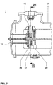
- eine Aufsicht auf einen längs der Linie VIII-VIII im wesentlichen quer zur Rohrachse geführten Schnitt durch den Trennschalter gemäss Fig.7, und
- Fig.9
- eine Aufsicht auf einen im quer zur Rohrachse geführten Schnitt durch ein im wesentlichen rohrförmig ausgebildetes Gehäuse einer dritten Ausführungsform des Trennschalters nach der Erfindung.
- 1
- Trennschalter
- 2
- Trennschaltergehäuse
- 3, 4, 5, 6
- Flanschansätze
- 7, 8, 9
- feststehende Schaltstücke
- 10
- Montagedeckel
- 11
- Antriebswelle
- 12
- Isolator
- 13
- Stromanschluss
- 14
- Flanschansatz
- 15, 16, 17
- bewegliche Schaltstücke
- 18, 19, 20
- Schaltstellen
- 21, 22, 23
- Schaltstellenachsen
- 24
- Abschirmung
- 25
- Getriebe
- 26, 27, 28
- Steuerscheiben
- 29, 30, 31,
- Hebel
- 32, 33, 34 35, 36
- Führungskurven
- 39, 40, 41, 42
- Kurvenabschnitte
- 43, 44
- Anschlagstellen
- 45
- Langloch
- 46
- Führungskurve
- 47
- Hebel
- 48, 49
- Kurvenabschnitte
- 50, 51
- Anschlagstellen
- 52, 53
- Kurvenabschnitte
- 290, 300
- Führungsteile
Claims (12)
- Trennschalter (1) mit einem Trennschaltergehäuse (2), mindestens zwei im Trennschaltergehäuse (2) angeordneten, axialsymmetrisch ausgebildeten Schaltstellen (18, 19, 20) mit jeweils einem feststehenden (7, 8, 9) und einem längs der Schaltstellenachse (21, 22, 23) beweglichen Schaltstück (15, 16, 17), einer ins Trennschaltergehäuse (2) geführten Antriebswelle (11) und mit einem Kraft von der Antriebswelle (11) auf das bewegliche Schaltstück (15, 16, 17) übertragenden Getriebe (25), dadurch gekennzeichnet, dass das Getriebe (25) für jede der Schaltstellen (18, 19, 20) mindestens eine mit dem beweglichen Schaltstück (15, 16, 17) fest verbundene, quer zur Wellenachse (11) ausgerichtete und verschiebbare Steuerscheibe (26, 27, 28) aufweist sowie mindestens einen an der Antriebswelle (11) befestigten und mit der Steuerscheibe (26, 27, 28) zusammenwirkenden Hebel (29,...,34; 47); wobei
die Steuerscheibe (26, 28) eine Führungskurve (46) aufweist, welche ein am Hebel (47) befestigtes Führungsteil beim Drehen der Welle (11) aufnimmt. - Trennschalter nach Anspruch 1, dadurch gekennzeichnet, dass die Führungskurve (46) zwei kreisbogenförmig ausgebildete Abschnitte (48, 49) sowie zwei zwischen diesen beiden Abschnitten (48, 49) angeordnete Anschlagstellen (50, 51; 52, 53) aufweist.
- Trennschalter nach Anspruch 2, dadurch gekennzeichnet, dass die Anschlagstellen (52, 53) schräg zur Schaltstellenachse (23) angeordnete Kurvenabschnitte sind.
- Trennschalter (1) mit einem Trennschaltergehäuse (2), mindestens zwei im Trennschaltergehäuse (2) angeordneten, axialsymmetrisch ausgebildeten Schaltstellen (18, 19, 20) mit jeweils einem feststehenden (7, 8, 9) und einem längs der Schaltstellenachse (21, 22, 23) beweglichen Schaltstück (15, 16, 17), einer ins Trennschaltergehäuse (2) geführten Antriebswelle (11) und mit einem Kraft von der Antriebswelle (11) auf das bewegliche Schaltstück (15, 16, 17) übertragenden Getriebe (25), dadurch gekennzeichnet, dass das Getriebe (25) für jede der Schaltstellen (18, 19, 20) mindestens eine mit dem beweglichen Schaltstück (15, 16, 17) fest verbundene, quer zur Wellenachse (11) ausgerichtete und verschiebbare Steuerscheibe (26, 27, 28) aufweist, und dass an der Antriebswelle (11) zwei mit der Steuerscheibe (26) zusammenwirkende Hebel (29, 30) befestigt sind, von denen beim Drehen der Antriebswelle (11) im Uhrzeigersinn ein erster (29) beim Einschalten und ein zweiter (30) beim Ausschalten und beim Drehen der Antriebswelle (11) im Gegenuhrzeigersinn der zweite (30) beim Einschalten und der erste (29) beim Ausschalten kraftschlüssig mit der Steuerscheibe (26) gekoppelt sind, wobei
die Steuerscheibe (26) zwei Führungskurven (35, 36) aufweist, von denen eine erste (35) ein am ersten Hebel (29) und eine zweite (36) ein am zweiten Hebel (30) befestigtes Führungsteil (290, 300) beim Drehen der Welle (11) aufnimmt. - Trennschalter nach Anspruch 4, dadurch gekennzeichnet, dass die Führungskurve (35, 36) jeweils zwei im wesentlichen kreisbogenförmig ausgebildete Abschnitte (39 - 42) aufweist sowie eine zwischen diesen beiden Abschnitten vorgesehene Anschlagstelle (43, 44).
- Trennschalter nach einem der Ansprüche 1 bis 5, dadurch gekennzeichnet, dass die Steuerscheibe (26) ein in Richtung der Schaltstellenachse (21) erstrecktes und die Antriebswelle (11) umfassendes Langloch (45) aufweist.
- Trennschalter nach einem der Ansprüche 4 bis 6, dadurch gekennzeichnet, dass die beiden Führungskurven (35, 36) auf entgegengesetzten Seiten der Steuerscheibe (26) angeordnet sind.
- Trennschalter nach einem der Ansprüche 4 bis 6, dadurch gekennzeichnet, dass die beiden Führungskurven (35, 36) jeweils auf einer von zwei Steuerscheiben angeordnet sind, und dass zwischen den beiden Steuerscheiben ein die zwei Führungsteile (290, 300) enthaltender Hebel angeordnet ist.
- Trennschalter nach einem der Ansprüche 4 bis 8, dadurch gekennzeichnet, dass die beiden Führungskurven (35, 36) jeweils als Nut in die Steuerscheibe eingeformt sind.
- Trennschalter nach einem der Ansprüche 4 bis 9, dadurch gekennzeichnet, dass die Hebel (29,...,34) in Richtung der Achse der Antriebswelle (11) axial gegeneinander versetzt sind.
- Trennschalter nach einem der Ansprüche 1 bis 10, dadurch gekennzeichnet, dass die mindestens zwei Schaltstellen (18, 19) jeweils mit einer Sammelschiene oder einem Leitungsabgang elektrisch leitend verbindbar sind.
- Trennschalter nach Anspruch 11, dadurch gekennzeichnet, dass ein feststehendes Schaltstück (9) einer dritten Schaltstelle (20) mit dem Trennschaltergehäuse (2) elektrisch leitend verbunden ist.
Applications Claiming Priority (2)
| Application Number | Priority Date | Filing Date | Title |
|---|---|---|---|
| DE19615912 | 1996-04-22 | ||
| DE19615912A DE19615912A1 (de) | 1996-04-22 | 1996-04-22 | Trennschalter |
Publications (3)
| Publication Number | Publication Date |
|---|---|
| EP0803888A2 EP0803888A2 (de) | 1997-10-29 |
| EP0803888A3 EP0803888A3 (de) | 1999-04-07 |
| EP0803888B1 true EP0803888B1 (de) | 2002-11-13 |
Family
ID=7792035
Family Applications (1)
| Application Number | Title | Priority Date | Filing Date |
|---|---|---|---|
| EP97810153A Expired - Lifetime EP0803888B1 (de) | 1996-04-22 | 1997-03-17 | Trennschalter |
Country Status (10)
| Country | Link |
|---|---|
| US (1) | US5841087A (de) |
| EP (1) | EP0803888B1 (de) |
| JP (1) | JPH1040783A (de) |
| KR (1) | KR970071876A (de) |
| CN (1) | CN1165388A (de) |
| CA (1) | CA2200634A1 (de) |
| DE (2) | DE19615912A1 (de) |
| RU (1) | RU2173498C2 (de) |
| UA (1) | UA46743C2 (de) |
| ZA (1) | ZA972680B (de) |
Cited By (1)
| Publication number | Priority date | Publication date | Assignee | Title |
|---|---|---|---|---|
| DE102006053376A1 (de) * | 2006-11-10 | 2008-05-15 | Abb Technology Ag | Elektrische Hochspannugnsanlage |
Families Citing this family (24)
| Publication number | Priority date | Publication date | Assignee | Title |
|---|---|---|---|---|
| DE19816366C1 (de) * | 1998-04-03 | 1999-11-11 | Siemens Ag | Kapselungsbaustein mit einem dreiphasigen Schaltgerät für eine gasisolierte Hochspannungsschaltanlage |
| DE19907887A1 (de) * | 1999-02-24 | 2000-08-31 | Asea Brown Boveri | Steuerscheibe für Getriebe eines Trennschalters und ein Verfahren zur Herstellung einer solchen Steuerscheibe |
| DE10205334C1 (de) * | 2002-02-06 | 2003-11-13 | Siemens Ag | Elektrische Schaltanordnung mit einem ersten Schaltkontakt und mit einem zweiten Schaltkondakt |
| US6723939B2 (en) | 2002-09-11 | 2004-04-20 | Eaton Corporation | Isolation switch for electric power systems |
| DE102004006061A1 (de) * | 2004-01-30 | 2005-08-18 | Siemens Ag | Hochspannungs-Freiluft-Durchführungsanordnung |
| DE102006031220A1 (de) * | 2006-06-30 | 2008-01-03 | Siemens Ag | Getriebeanordnung zum Antrieb eines elektrischen Schaltkontaktes |
| DE102009030608A1 (de) | 2009-06-23 | 2010-12-30 | Siemens Aktiengesellschaft | Hochspannungsanordnung |
| DE102009036590B3 (de) * | 2009-08-07 | 2011-03-31 | Abb Technology Ag | Gasisolierte Hochspannungsschaltanlage |
| MX2012008382A (es) * | 2010-01-18 | 2012-08-15 | Abb Technology Ag | Carcasa de un montaje aislado con gas comprimido para una unidad de dispositivo de distribucion electrica. |
| EP2591487B1 (de) * | 2010-07-07 | 2017-08-30 | Siemens Ltd. | Elektrischer trennschalter |
| WO2012101758A1 (ja) | 2011-01-25 | 2012-08-02 | 三菱電機株式会社 | 開閉器 |
| KR101212783B1 (ko) * | 2011-06-28 | 2012-12-18 | 현대중공업 주식회사 | 가스절연기기용 3-way 스위치 |
| CN102867676A (zh) * | 2012-09-26 | 2013-01-09 | 中电装备恩翼帕瓦(山东)高压开关有限公司 | 一种改进的隔离开关单元 |
| CN103177901B (zh) * | 2012-12-24 | 2015-12-09 | 宁波优维电力科技有限公司 | 一种三工位开关操作机构 |
| DE102013205354B3 (de) * | 2013-03-26 | 2014-07-10 | Alstom Technology Ltd. | Elektrische Schaltanlage |
| EP2824686A1 (de) * | 2013-07-10 | 2015-01-14 | Siemens Aktiengesellschaft | Elektrische Hochspannungsschaltanordnung unter einer Metallschutzhülle |
| DE102015205915A1 (de) * | 2015-04-01 | 2016-10-06 | Siemens Aktiengesellschaft | Verschlussbaugruppe mit einer Wandung |
| EP3312864B1 (de) * | 2016-10-24 | 2019-07-31 | Siemens Aktiengesellschaft | Multifunktionelles schaltmodul für kompakte hochspannungs-schaltanlage |
| EP3748792B1 (de) * | 2018-01-31 | 2024-04-24 | Mitsubishi Electric Corporation | Gasisolierte schaltvorrichtung |
| EP3624163A1 (de) * | 2018-09-17 | 2020-03-18 | Microelettrica Scientifica S.p.A. | Schalter und umschalter mit kompakter struktur |
| ES1229781Y (es) * | 2019-04-26 | 2019-08-12 | Ormazabal Y Cia S L U | Interruptor de corte en gas |
| CN111981971A (zh) * | 2020-07-16 | 2020-11-24 | 湖南长高高压开关集团股份公司 | 折臂式隔离开关分合闸到位检测方法及装置 |
| ES1276579Y (es) * | 2021-03-23 | 2021-11-15 | Ormazabal Y Cia S L U | Aparamenta eléctrica aislada en gas para redes de distribución eléctrica de media y alta tensión |
| CN114512366B (zh) * | 2022-03-08 | 2022-11-15 | 山东大学 | 一种三位置隔离开关机构的缓冲限位装置及操动机构 |
Family Cites Families (12)
| Publication number | Priority date | Publication date | Assignee | Title |
|---|---|---|---|---|
| US3794799A (en) * | 1972-03-27 | 1974-02-26 | Westinghouse Electric Corp | Gas insulated switch with adjustable overcenter toggle actuator therefore |
| NL159830B (nl) * | 1974-03-18 | 1979-03-15 | Coq Bv | Gesloten elektrische schakelinrichting voor hoge spanningen met in een gesloten keten in serie geschakelde schakelvel- den. |
| NL160439C (nl) * | 1975-04-07 | 1979-10-15 | Coq Bv | Vermogensschakelaar voor hoge spanning met bolvormig metalen vat. |
| JPS6025849B2 (ja) * | 1976-04-27 | 1985-06-20 | 株式会社東芝 | 密閉形開閉装置 |
| DE2838373C2 (de) * | 1978-09-02 | 1980-02-14 | Eduard 7303 Neuhausen Hermle | Schaltwerk |
| US4300028A (en) * | 1979-09-25 | 1981-11-10 | Gould Inc. | Rotary switch for gas-insulated substations |
| US4379957A (en) * | 1981-01-14 | 1983-04-12 | Westinghouse Electric Corp. | Modular "Y"-type enclosure elements for gas insulated substations |
| CH654139A5 (de) * | 1981-04-22 | 1986-01-31 | Sprecher & Schuh Ag | Hochspannungsschalter. |
| DE3126745A1 (de) * | 1981-07-02 | 1983-01-20 | Siemens AG, 1000 Berlin und 8000 München | Dreipolige kabelanschlusseinheit fuer eine dreipolige metallgekapselte, druckgasisolierte hochspannungsschaltanlage |
| DE3421265A1 (de) * | 1983-06-10 | 1984-12-13 | Mitsubishi Denki K.K., Tokio/Tokyo | Schaltgeraet |
| DE4211155A1 (de) * | 1992-03-31 | 1993-10-07 | Siemens Ag | Gasisolierte Schaltanlage mit einem mehrpoligen Vakuumschalter und einem mehrpoligen Lasttrennschalter |
| DE4336951A1 (de) * | 1993-10-29 | 1995-05-04 | Abb Management Ag | Hochspannungsschaltgerät |
-
1996
- 1996-04-22 DE DE19615912A patent/DE19615912A1/de not_active Withdrawn
-
1997
- 1997-03-17 EP EP97810153A patent/EP0803888B1/de not_active Expired - Lifetime
- 1997-03-17 DE DE59708688T patent/DE59708688D1/de not_active Expired - Fee Related
- 1997-03-21 CA CA002200634A patent/CA2200634A1/en not_active Abandoned
- 1997-03-21 US US08/821,928 patent/US5841087A/en not_active Expired - Fee Related
- 1997-03-27 ZA ZA9702680A patent/ZA972680B/xx unknown
- 1997-04-18 UA UA97041860A patent/UA46743C2/uk unknown
- 1997-04-21 JP JP9103586A patent/JPH1040783A/ja not_active Withdrawn
- 1997-04-21 RU RU97106249/09A patent/RU2173498C2/ru not_active IP Right Cessation
- 1997-04-22 KR KR1019970014957A patent/KR970071876A/ko not_active Abandoned
- 1997-04-22 CN CN97110567A patent/CN1165388A/zh active Pending
Cited By (1)
| Publication number | Priority date | Publication date | Assignee | Title |
|---|---|---|---|---|
| DE102006053376A1 (de) * | 2006-11-10 | 2008-05-15 | Abb Technology Ag | Elektrische Hochspannugnsanlage |
Also Published As
| Publication number | Publication date |
|---|---|
| CN1165388A (zh) | 1997-11-19 |
| ZA972680B (en) | 1997-10-22 |
| RU2173498C2 (ru) | 2001-09-10 |
| CA2200634A1 (en) | 1997-10-22 |
| EP0803888A3 (de) | 1999-04-07 |
| DE19615912A1 (de) | 1997-10-23 |
| JPH1040783A (ja) | 1998-02-13 |
| KR970071876A (ko) | 1997-11-07 |
| EP0803888A2 (de) | 1997-10-29 |
| UA46743C2 (uk) | 2002-06-17 |
| US5841087A (en) | 1998-11-24 |
| DE59708688D1 (de) | 2002-12-19 |
Similar Documents
| Publication | Publication Date | Title |
|---|---|---|
| EP0803888B1 (de) | Trennschalter | |
| DE69602200T2 (de) | Hybrid-hochspannungsschalter | |
| DE69929229T2 (de) | Gasisolierte schaltvorrichtung | |
| DE69905065T2 (de) | Gasisolierte schaltvorrichtung | |
| DE3810453C2 (de) | ||
| DE2831134C2 (de) | Metallgekapseltes, druckgasisoliertes Hochspannungsschaltgerät | |
| EP2534663B1 (de) | Stufenschalter mit freilaufelement | |
| EP0796501B1 (de) | Dreistellungsschalterantrieb für mittelspannungsschaltanlagen | |
| EP1719143A1 (de) | Schaltger t mit trenn- und/oder erdungsfunktion | |
| DE69516461T2 (de) | Mittelspannung elektrischer Schalter | |
| DE19524636C1 (de) | Mehrphasiger Hochspannungsschalter | |
| EP0763839A2 (de) | Antrieb für das bewegbare Kontaktstück eines Trenn-Erdungsschalters | |
| DE2250738A1 (de) | Loesbare stromabnehmervorrichtung fuer eine einen im wesentlichen u-foermigen querschnitt aufweisende stromschiene | |
| EP2337047A1 (de) | Elektrischer Leistungsschalter sowie Schaltstellungsanzeige hierfür | |
| DE102016117786A1 (de) | Elektrischer Schalter | |
| EP0508041B1 (de) | Schaltantrieb für elektrische Geräte der Mittelspannungstechnik | |
| DE2923019C2 (de) | Hochspannungsschalter | |
| WO2005034156A1 (de) | Vorrichtung zur betätigung eines elektrischen schaltgerätes | |
| EP0546283A2 (de) | Polungsschalter für Stufenwähler | |
| DE3313729C2 (de) | Hochspannungsschalter | |
| DE3143279C2 (de) | Erdungsvorrichtung an einer isolierstoffgekapselten Mittelspannungs-Schaltanlage | |
| AT413166B (de) | Elektrische anlage, insbesondere für den mittelspannungsbereich, mit einem mittels kurbelantrieb verfahrbaren einfahreinsatz | |
| DE2737020B1 (de) | Vorrichtung fuer stufenweisen Bewegungsablauf | |
| EP3834219B1 (de) | Gasisolierte schaltanlage | |
| DE2850761B2 (de) | Sprungantriebsvorrichtung für elektrische Schaltgeräte |
Legal Events
| Date | Code | Title | Description |
|---|---|---|---|
| PUAI | Public reference made under article 153(3) epc to a published international application that has entered the european phase |
Free format text: ORIGINAL CODE: 0009012 |
|
| AK | Designated contracting states |
Kind code of ref document: A2 Designated state(s): CH DE FR GB LI |
|
| PUAL | Search report despatched |
Free format text: ORIGINAL CODE: 0009013 |
|
| RHK1 | Main classification (correction) |
Ipc: H01H 31/20 |
|
| AK | Designated contracting states |
Kind code of ref document: A3 Designated state(s): CH DE FR GB LI |
|
| 17P | Request for examination filed |
Effective date: 19990614 |
|
| RAP1 | Party data changed (applicant data changed or rights of an application transferred) |
Owner name: ABB HOCHSPANNUNGSTECHNIK AG |
|
| 17Q | First examination report despatched |
Effective date: 20010817 |
|
| GRAG | Despatch of communication of intention to grant |
Free format text: ORIGINAL CODE: EPIDOS AGRA |
|
| RAP1 | Party data changed (applicant data changed or rights of an application transferred) |
Owner name: ABB SCHWEIZ AG |
|
| GRAG | Despatch of communication of intention to grant |
Free format text: ORIGINAL CODE: EPIDOS AGRA |
|
| GRAH | Despatch of communication of intention to grant a patent |
Free format text: ORIGINAL CODE: EPIDOS IGRA |
|
| GRAH | Despatch of communication of intention to grant a patent |
Free format text: ORIGINAL CODE: EPIDOS IGRA |
|
| GRAA | (expected) grant |
Free format text: ORIGINAL CODE: 0009210 |
|
| AK | Designated contracting states |
Kind code of ref document: B1 Designated state(s): CH DE FR GB LI |
|
| REG | Reference to a national code |
Ref country code: GB Ref legal event code: FG4D Free format text: NOT ENGLISH |
|
| REG | Reference to a national code |
Ref country code: CH Ref legal event code: EP |
|
| REF | Corresponds to: |
Ref document number: 59708688 Country of ref document: DE Date of ref document: 20021219 |
|
| PGFP | Annual fee paid to national office [announced via postgrant information from national office to epo] |
Ref country code: CH Payment date: 20030218 Year of fee payment: 7 |
|
| PGFP | Annual fee paid to national office [announced via postgrant information from national office to epo] |
Ref country code: GB Payment date: 20030226 Year of fee payment: 7 |
|
| PGFP | Annual fee paid to national office [announced via postgrant information from national office to epo] |
Ref country code: DE Payment date: 20030311 Year of fee payment: 7 |
|
| PGFP | Annual fee paid to national office [announced via postgrant information from national office to epo] |
Ref country code: FR Payment date: 20030314 Year of fee payment: 7 |
|
| GBT | Gb: translation of ep patent filed (gb section 77(6)(a)/1977) |
Effective date: 20030226 |
|
| ET | Fr: translation filed | ||
| PLBE | No opposition filed within time limit |
Free format text: ORIGINAL CODE: 0009261 |
|
| STAA | Information on the status of an ep patent application or granted ep patent |
Free format text: STATUS: NO OPPOSITION FILED WITHIN TIME LIMIT |
|
| 26N | No opposition filed |
Effective date: 20030814 |
|
| PG25 | Lapsed in a contracting state [announced via postgrant information from national office to epo] |
Ref country code: GB Free format text: LAPSE BECAUSE OF NON-PAYMENT OF DUE FEES Effective date: 20040317 |
|
| PG25 | Lapsed in a contracting state [announced via postgrant information from national office to epo] |
Ref country code: LI Free format text: LAPSE BECAUSE OF NON-PAYMENT OF DUE FEES Effective date: 20040331 Ref country code: CH Free format text: LAPSE BECAUSE OF NON-PAYMENT OF DUE FEES Effective date: 20040331 |
|
| PG25 | Lapsed in a contracting state [announced via postgrant information from national office to epo] |
Ref country code: DE Free format text: LAPSE BECAUSE OF NON-PAYMENT OF DUE FEES Effective date: 20041001 |
|
| GBPC | Gb: european patent ceased through non-payment of renewal fee |
Effective date: 20040317 |
|
| REG | Reference to a national code |
Ref country code: CH Ref legal event code: PL |
|
| PG25 | Lapsed in a contracting state [announced via postgrant information from national office to epo] |
Ref country code: FR Free format text: LAPSE BECAUSE OF NON-PAYMENT OF DUE FEES Effective date: 20041130 |
|
| REG | Reference to a national code |
Ref country code: FR Ref legal event code: ST |