EP0803844A2 - Münzspeicher - Google Patents
Münzspeicher Download PDFInfo
- Publication number
- EP0803844A2 EP0803844A2 EP97202083A EP97202083A EP0803844A2 EP 0803844 A2 EP0803844 A2 EP 0803844A2 EP 97202083 A EP97202083 A EP 97202083A EP 97202083 A EP97202083 A EP 97202083A EP 0803844 A2 EP0803844 A2 EP 0803844A2
- Authority
- EP
- European Patent Office
- Prior art keywords
- coin
- stack
- coins
- dispensing
- motor
- Prior art date
- Legal status (The legal status is an assumption and is not a legal conclusion. Google has not performed a legal analysis and makes no representation as to the accuracy of the status listed.)
- Granted
Links
- 230000003287 optical effect Effects 0.000 claims description 19
- 230000002441 reversible effect Effects 0.000 claims description 7
- 238000000926 separation method Methods 0.000 claims description 3
- 230000004913 activation Effects 0.000 claims 1
- 230000000712 assembly Effects 0.000 claims 1
- 238000000429 assembly Methods 0.000 claims 1
- 230000005540 biological transmission Effects 0.000 claims 1
- 230000007246 mechanism Effects 0.000 abstract description 11
- 230000008859 change Effects 0.000 abstract description 6
- 238000010586 diagram Methods 0.000 description 5
- 238000000034 method Methods 0.000 description 3
- 230000008569 process Effects 0.000 description 3
- 230000004044 response Effects 0.000 description 3
- 238000012986 modification Methods 0.000 description 2
- 230000004048 modification Effects 0.000 description 2
- 239000007787 solid Substances 0.000 description 2
- 241000237858 Gastropoda Species 0.000 description 1
- 238000013459 approach Methods 0.000 description 1
- 238000013461 design Methods 0.000 description 1
- 230000001939 inductive effect Effects 0.000 description 1
- 238000007689 inspection Methods 0.000 description 1
- 230000014759 maintenance of location Effects 0.000 description 1
- 239000000463 material Substances 0.000 description 1
- 238000012544 monitoring process Methods 0.000 description 1
- 229920003023 plastic Polymers 0.000 description 1
- 239000004033 plastic Substances 0.000 description 1
- 230000036316 preload Effects 0.000 description 1
- 230000005855 radiation Effects 0.000 description 1
- 230000000717 retained effect Effects 0.000 description 1
- 238000001429 visible spectrum Methods 0.000 description 1
Images


Classifications
-
- G—PHYSICS
- G07—CHECKING-DEVICES
- G07F—COIN-FREED OR LIKE APPARATUS
- G07F11/00—Coin-freed apparatus for dispensing, or the like, discrete articles
- G07F11/02—Coin-freed apparatus for dispensing, or the like, discrete articles from non-movable magazines
- G07F11/04—Coin-freed apparatus for dispensing, or the like, discrete articles from non-movable magazines in which magazines the articles are stored one vertically above the other
-
- G—PHYSICS
- G07—CHECKING-DEVICES
- G07D—HANDLING OF COINS OR VALUABLE PAPERS, e.g. TESTING, SORTING BY DENOMINATIONS, COUNTING, DISPENSING, CHANGING OR DEPOSITING
- G07D9/00—Counting coins; Handling of coins not provided for in the other groups of this subclass
- G07D9/06—Devices for stacking or otherwise arranging coins on a support, e.g. apertured plate for use in counting coins
-
- G—PHYSICS
- G07—CHECKING-DEVICES
- G07F—COIN-FREED OR LIKE APPARATUS
- G07F5/00—Coin-actuated mechanisms; Interlocks
- G07F5/24—Coin-actuated mechanisms; Interlocks with change-giving
Definitions
- This invention relates to a coin store. More particularly, this invention relates to a coin store for use in coin operated machinery, of the type in which the last coin to enter the store is the first to be dispensed therefrom.
- coin operated machinery for example, gaming machines
- coins are received at a coin entry slot; passed through a coin acceptor mechanism to validate the coins; and, if accepted, are deposited into the top of a change tube storing a stack of coins.
- the lowermost coin is dispensed from the bottom of the tube into a coin exit in a pay-out tray, the stack of coins drops, and the next coin (if required) is dispensed.
- a first problem with this arrangement is that the height of the tube, and hence the number of coins which the tube can store, is limited by the acceptable distance between the coin entry slot and the pay-out tray; for ergonomic reasons, the pay-out tray cannot be placed too low or the coin entry slot too high.
- a second problem is that, on dispensing a coin the force rehired to dispense a coin from the bottom of the tube can be relatively high, due to the weight of the coins above it in the tube. Finally, it is possible to defraud the gaming machine by inserting counterfeit coins into the entry slot so that they are deposited into the top of the change tube, and receiving genuine coins in return from the bottom of the change tube.
- a reversible motor is arranged to raise or lower the stack of coins in the coin store, in response to control signals from a microprocessor. Sensors are provided in the coin inlet channel and in the coin dispensing channel, leading respectively to and from the store, so that when a coin approaches the store the microprocessor can cause the motor to drive the stack of coins downward to receive the new coin.
- the microprocessor causes the motor to raise the stack of coins.
- the motor is also geared to a coin dispensing device, which is therefore driven at the same time to push the uppermost coin off the stack towards the coin exit.
- a microswitch sensor is provided above the coin stack, so that when the coin stack is driven upwards the microswitch is actuated, causing the uppermost coin to be dispensed.
- a control device controls a reversible motor to raise or lower the coin stack in the coin store.
- a control device operates in a first mode when coins are being stacked within the coin store, in which mode the control device responds to an inductive sensor at the top of the stack to lower the stack until there is no signal from the sensor (i.e. when the uppermost coin lies below the sensor).
- the control device operates in a second mode when it is desired to dispense coins, in which mode the motor is operated to raise a coin stack until the uppermost coin rises above the top of the coin store; since the coin stack is inclined, the coin falls through an exit channel towards the coin exit.
- a sensor disposed in the exit channel counts the coins, and, when the desired number of coins have passed the sensor, the control device halts upward movement of the coin stack.
- a coin store comprising means for forming a stack of coins, a common coin entry and exit point at one end of the coin stack, means for moving the stack of coins away from and towards that end of the coin stack, and means for dispensing a coin from that end, characterised in that there is provided a positioning system for maintaining the endmost coin in the stack in a position from which it can be dispensed by the dispensing means, and in that on dispensing coins, the dispensing means is actuated prior to any actuation of the stack moving means.
- the endmost coin is positioned ready for dispensing as a separate and prior operation to the operation of dispensing a coin. Because the position of the endmost coin is established prior to dispensing, the likelihood of jamming, or over or under payment is reduced. Where multiple coins are to be paid out, the position of each can be clearly established prior to dispensing.
- a coin stack positioning system which comprises first and second sensors for sensing first and second positions separated along the length of the coin stack by a separation less than the width of the coin, and positioning means arranged to be responsive to the sensor outputs, to position a coin to lie with an outer portion thereof between the first and second sensors.
- a coin store comprising means for forming a stack of coins, a common coin entry and exit point at one end of the coin stack, means for moving the stack of coins away from and towards that end of the coin stack, and means for dispensing a coin from that end, characterised by means for detecting the length of the coin stack, and means for maintaining a count of the number of coins in the stack based on the detected length.
- the length of the coin stack may be detected by detecting movements of the stack moving means (preferably by providing an indexing system, for example an optical indexing system) to track upwards movements of the coin stack which correspond to dispensing a coin or downwards movements of the coin stack, which correspond to accepting a coin.
- an indexing system for example an optical indexing system
- coin is intended to include coin-like tokens, whether or not they are official or convertible currency, and (where appropriate) counterfeit coins or "slugs".
- a coin-operated machine comprises a housing 1, a coin entry slot 10, a coin acceptor mechanism 20, a coin store 30, and a coin outlet 40.
- a first coin entry channel 50 interconnects the coin entry slot 10 and coin acceptor 20;
- a second coin entry channel 60 interconnects the coin acceptor 20 and the coin store 30, and
- a coin exit channel 70 interconnects the coin store 30 and the coin outlet 40.
- the coin entry slot 10, coin acceptor 20, housing 1, coin outlet 40 and coin control 50, 60, 70 are in themselves of generally conventional design.
- the acceptor may be as described in our earlier application GB-A-2094008 or GB-A-2093620.
- Also present, indicated generally by 2 is conventional coin-operated machinery (for example, for playing a game) which is actuated in response to acceptance of a coin by the coin acceptor 20.
- a plurality of such coin stores 20a, 20b ... etc are provided, connected via respective coin entry channels 60a, 60b ... to respective outlets of the coin acceptor 20 and via respective outlet channels 70a, 70b ... to the coin outlet 40.
- a coin is inserted into the coin entry slot 10 and rolls down the coin channel 50 to the acceptor 20. If the coin is acceptable, the acceptor 20 passes it to the inlet channel 60, through which it rolls into the coin store 30. The coin is received onto the top of a stack of coins in the store, the top of which is kept at a constant level, as detailed below. If the coin is rejected, the acceptor 20 passes it through a reject coin channel (omitted from Figure 1 for clarity) to the coin outlet 40.
- the control unit 3 of the coin operated machinery 2 supplies a command signal to a control circuit 80 of the coin store 30 to supply the uppermost coin to the coin exit channel 70, down which it rolls to the coin outlet 40 which comprises a payout tray from which it may be retrieved by the user.
- the coin store comprises a tubular housing 21, which in this embodiment is of a translucent plastics material to allow inspection of the length of the coin stack.
- the housing 21 in this embodiment is intended to be vertically oriented, to receive a vertical stack of coins lying flat (i.e. normal to the axis of the housing 21), and is accordingly of generally circular cross-section.
- the tubular housing 21 is a continuous tube, but for clarity portions of the tube are omitted from Figures 3, 4 and 5 so as to allow other features to be seen.
- a coin stack support platform 22 comprising a cylindrical block having a coin-receiving surface in the part of the housing 21 which, in use, is the upper part. Coins are received onto the platform 22 to form a stack, which is moved within the housing 21 by moving the platform 22.
- a stack drive system (shown in greater detail in Figure 4) comprising a motor 23 mounted fixedly to the housing 21 and connected through an input drive shaft 24 via a worm gear to a horizontal axle 25 which is connected at each end to a respective drive pulley 26a, 26b, via oppositely acting worm and wheel gear pairs 27a, 27b.
- An endless drive belt 28 runs over the drive pulleys 26a, 26b to form a bight therebetween which passes through the upper part (in use) of the platform 22.
- the belt 28 passes vertically along the length of the tubular housing 21 to pass over a pair of idler pulleys 29a, 29b aligned with the drive pulleys 26a, 26b.
- the belt 28 forms a second bight through the lower part of the support platform 22.
- a belt tensioner Located within the platform 22 (not shown in Figure 4) is a belt tensioner comprising a block 31 engaging the belt 28 and moveable axially within the platform 22, so as to allow, on assembly, the belt 28 to be tensioned within the piston 22 and then locked in the tensioned position by a locking screw (not shown).
- the portions of the belt 28 forming the bights are located to travel within a pair of opposed channels 32a, 32b on the inside of the tubular housing 21 and the axially running outer portions of the belt 28 are located to travel within a pair of channels 33a, 33b on the outside of the tubular housing 21.
- the drive train 24-27 is located within a drive housing 34 at the upper end of the housing 21, the housing 34 including an opening aligned with the tubular housing 21, through which the stack of coins may be raised or lowered.
- a pair of optical emitters 35a, 35b and a pair of optical receivers 36a, 36b located above the drive housing 34.
- the first emitter 35a is aligned with the first receiver 36a to define a beam path A running diagonally across the center of the opening in the drive housing 34, and the second emitter is likewise aligned with the second receiver 35b, 36b to define a second beam path B.
- the beam heights are, in this embodiment, each 0.5mm, and the second emitter and receiver 35b, 36b are positioned 0.5mm above the first so that the second beam B lies just above the first.
- a coin displacing mechanism comprising a bar 37 aligned, in this embodiment, normal to the axis of the tubular housing 21 (i.e. parallel to the planes of the surfaces of coins therein).
- the bar 37 is in engagement with a linear actuator 38 comprising a rack on the surface of the bar 37 engaging with a toothed wheel 38 driven by a reversible motor 39 (not shown) such that the bar 37 can be withdrawn (leftwards in Figure 6) to a rest position in which it does not obtrude into the opening in the housing 34, and from which it can be moved by rotation of the motor 39 to traverse the upper surface of the drive housing 34.
- a coin when a coin is aligned so as to lie in the plane of the bar 37 and proud of the upper surface of the drive housing 34, the coin can be displaced into the exit channel 70 by actuating the bar 37 to push the coin off the top of the stack, and then withdrawing the bar 37.
- Figure 7 shows illustratively the arrangement of the two beams A, B and the bar 37.
- the stack drive system motor 23 and the dispenser motor 39 are energised by the coin stack control circuit 80.
- the control circuit 80 performs movement of the stack (via the drive motor 23) and dispensing from the stack (via the dispensing motor 39) as separate operations, movement of the stack overriding the operation of dispensing from the stack.
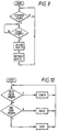
- control circuit 80 When a control signal is received from the machine control unit 3, indicating that a coin is to be dispensed, as shown in Figure 9, if the stack drive motor 23 is not running, the control circuit 80 actuates the dispensing motor 39 so as to rotate (clockwise in Figure 6) to extend the bar 37 across the stack or coins (so that it engages the uppermost coin in the stack and pushes it off the stack and onto the exit channel 70), then reverses the direction of the motor 39 so as to return the bar 37 to its rest position.
- a timing circuit may be provided to control the reversal of the direction of the dispensing motor 39, or alternatively a pair of microswitches or other sensors may be provided, to be actuated by the bar 37 or the wheel 38 at positions where the bar 37 is at its maximum extent of travel and at its rest position.
- control circuit 80 is arranged to maintain the uppermost coin in the stack ready for dispensing at a predetermined dispensing position.
- control circuit 80 is arranged to respond to the outputs of the two optical sensors 36a, 36b such that if the outputs of both sensors are low (i.e. if both paths are broken) and therefore a coin has risen above the level of the sensor 36b, the motor 23 is energised to lower the stack support platform 22 and hence the uppermost coin.
- the motor 23 is energised to raise the stack Support platform 22 and hence the uppermost coin.
- the motor 23 is not energised.
- Each detector 36a, 36b may be a commercially available device, and is preferably associated with thresholding circuitry to give a logic level output depending upon whether the received light lies above or below a threshold intensity.
- Each optical emitter device 35a, 35b in this embodiment comprises a light emitting diode, arranged to generate a beam 0.5mm x 2mm in cross section (for example through an associated curved prism) focused onto the respective optical receiver device.
- the vertical separation between the two beams A, B is small, and preferably smaller than the thickness of the smallest type of coin to be received so that the apparatus operates independently of the actual coin denomination present in the coin tube.
- the bar 37 is arranged to engage the uppermost 1mm of the uppermost coin in the stack, and accordingly the bar 37 is positioned so that it extends 1mm (which, as mentioned above, corresponds to the thinnest coin received in the coin store) downwardly from the plane between the beams A, B.
- the bar 37 will dispense only a single coin at a time.
- the upper surface of the bar 37 is aligned to move in the plane lying between the sensors 36a and 36b.
- the stack drive motor 23 raises the coin support platform 22 until the lower beam A is once more broken, indicating that the next coin is ready to be dispensed.
- the height of each beam (and the vertical distance between the beams) is no greater than the width of the smallest expected coin, and is preferably no greater than half the width of the coin.
- the detectors are made responsive to coins of different diameters.
- the beams A, B are not parallel (and preferably, as shown, divide the opening in the housing 34 into four or more equal radial segments)
- the sensors 36a, 36b are made responsive to tilted coins, since no matter what the angle of tilt of position of the coin, it will be raised until it impinges upon one or more of the beams.
- the control circuit 80 comprises a pair of switch circuits 83, 84, the first switch circuit 83 interconnecting the supply and earth lines with the motor 23 and the second switch circuit 84 interconnecting the supply and earth lines with the motor 39.
- Each of the switch units is operative to connect the respective motor in one of three states; a de-energised state in which no potential difference is connected across the motor, a forward state in which the supply and earth lines are connected in a first direction across the motor, and a reverse state in which the supply and earth lines are connected in the reverse direction across the motor.
- the switch unit 83 which controls the stack drive motor 23 is controlled by a stack drive control circuit 81 connected to the outputs of the optical sensors 36a, 36b and the switch unit 84 controlling the dispensing motor 39 is controlled by a dispensing control unit 82, operative in response to a dispense command.
- the control circuit 80 is typically provided by a suitably programmed microprocessor or large scale integrated circuit, executing the process of Figures 9 and 10.
- control circuits 81 and 82 could comprise discrete logic circuits operating in accordance with the processes of Figures 9 and 10.
- the stack drive control circuit 81 could thus simply comprise three logic gates 83, 84, 85, to combine the detector outputs in AND, NOR and XOR relationship, to respectively raise, lower or stop the motor 23 via the switch unit 83.
- the dispenser mechanism comprising the motor 39, wheel 38, and bar 37 are in this embodiment provided, together with the optical emitters 35a, 35b and receivers 36a, 36b, in a unit which is mounted within the machine 1 together with the control circuit 80.
- the tubular housing 21, drive motor 23 and drive system housing 34 are provided as a removable unit, which may be inserted into the housing in alignment with the dispensing mechanism, the drive motor 23 being detachably interconnected to the control circuit 80.
- a full or empty coin store may be removed by human operator and replaced by another coin store without needing extensive realignment or repositioning since the sensors and the dispensing mechanism are co-located and their positional relationship is unchanged so that whatever tubular housing 21 lies beneath the sensors, the top of the uppermost coin is brought to the same position for dispensing.
- the input drive shaft 24 may be positioned on the uppermost face of the housing 34, and the motor may be positioned directly above it in the apparatus, so that the tube may simply be lifted into engagement with the motor and the sensor system, and retained by some retention means (not shown). This simplifies the changing of tubes. It is also possible for the drive shaft 24 to be solid with the motor 23, and an orifice to be provided in the housing 34 to allow the housing 34 to be assembled to the drive shaft 24.
- the coin tube assembly described above may be machine readable indicia, from which the identity of the coins within the tubes can be detected.
- the indicia may be a set of contact pins or contact strips, arranged for contact with pins or pads on the apparatus into which the tube is assembled, and encoding the identity of the contents of the tube in binary or other coded form.
- optical or other indicia may be used.
- a coin count circuit 90 which keeps count of the number of coins in the coin store by monitoring movements of the coin stack drive system, using a position encoder associated with the drive system.
- the position encoder may be a rotary encoder on the input shaft 24, axle 25 or one of the pulleys 26a, 26b, 29a, 29b; or could be a linear encoder carried on the belt 28.
- Such encoders are well known and may for example consist of an optical sensor provided solid with the tubular housing 21 or some other fixed component, and a series of spaced features (e.g. light and dark optical bands) at predetermined intervals either radially (on a rotating component) or linearly (along the belt 28).
- a predetermined number of optical features are spaced so as to pass the optical sensor during a movement of the coin support platform 22 equivalent to the width of one coin.
- the predetermined number depends upon the thickness of the coin, and preferably the spacing between features is a small fraction of the width of the thinnest coin with which the store may be used, to allow accurate counting.
- the coin counter 90 comprises a light source 91 and a light detector 92, the source and detector 91, 92 being arranged so that the detector receives light from the source reflected from an encoder surface 93 comprising a plurality of parallel light bars spaced along the outer surface of the belt 28 at a predetermined spacing.
- the output of the optical pickup 92 is supplied to a commercially available up/down counter circuit device 94.
- Coupled to the up/down count control pin of the circuit 94 is a line taken from the output of the stack drive control circuit 81, so that when the coin stack is being raised the counter is controlled to count up and when the coin stack is being lowered the counter 94 is controlled to count down.
- the number held in the counter 94 indicates the change in the number or coins since power was first supplied to the counter 94.
- a divider circuit 95 which divides the count held in the counter by the predetermined number which comprises the ratio between the spacing between adjacent features and the width of the type of coin held in the store.
- the coin counter circuit 90 can therefore be adapted for use with a variety of different coin widths by merely changing the predetermined number utilised by the divider circuit 95; typically, several different predetermined numbers each corresponding to a member of a coin set with which the coin store may be used are programmed into the divider circuit 95, and the desired number corresponding to the coin type with which the store is being used is selected by a select signal from the machine control circuit 3.
- control circuit 80 may be arranged, on initial supply of power, to move the coin support platform to 22 to a predetermined position (for example, fully lowered within the tubular housing 21) sensed by, for example, a microswitch or other sensor, prior to supplying power to the counter circuit 94, and to preload the counter circuit 94 with a predetermined number corresponding to the predetermined position, so that subsequent coin counts represent an absolute rather than a relative number of coins.
- tubular housing has been described as moving vertically, it could in fact be inclined at an angle to the vertical.
- coin receiving surface of the coin support platform 22 need not be normal to the axis of the tubular housing 21, but could be inclined thereon so as to form a stack of coins having their surfaces inclined to that axis.
Landscapes
- Physics & Mathematics (AREA)
- General Physics & Mathematics (AREA)
- Control Of Vending Devices And Auxiliary Devices For Vending Devices (AREA)
- Pinball Game Machines (AREA)
- Basic Packing Technique (AREA)
Applications Claiming Priority (3)
| Application Number | Priority Date | Filing Date | Title |
|---|---|---|---|
| GB9310636A GB2278221B (en) | 1993-05-21 | 1993-05-21 | Coin store |
| GB9310636 | 1993-05-21 | ||
| EP94915627A EP0700553B1 (de) | 1993-05-21 | 1994-05-19 | Münzspeicher |
Related Parent Applications (2)
| Application Number | Title | Priority Date | Filing Date |
|---|---|---|---|
| EP94915627A Division EP0700553B1 (de) | 1993-05-21 | 1994-05-19 | Münzspeicher |
| EP94915627.7 Division | 1994-12-08 |
Publications (3)
| Publication Number | Publication Date |
|---|---|
| EP0803844A2 true EP0803844A2 (de) | 1997-10-29 |
| EP0803844A3 EP0803844A3 (de) | 1997-11-12 |
| EP0803844B1 EP0803844B1 (de) | 2007-08-15 |
Family
ID=10736008
Family Applications (2)
| Application Number | Title | Priority Date | Filing Date |
|---|---|---|---|
| EP94915627A Expired - Lifetime EP0700553B1 (de) | 1993-05-21 | 1994-05-19 | Münzspeicher |
| EP97202083A Expired - Lifetime EP0803844B1 (de) | 1993-05-21 | 1994-05-19 | Münzspeicher |
Family Applications Before (1)
| Application Number | Title | Priority Date | Filing Date |
|---|---|---|---|
| EP94915627A Expired - Lifetime EP0700553B1 (de) | 1993-05-21 | 1994-05-19 | Münzspeicher |
Country Status (6)
| Country | Link |
|---|---|
| US (1) | US5718625A (de) |
| EP (2) | EP0700553B1 (de) |
| DE (2) | DE69435014T2 (de) |
| ES (2) | ES2289756T3 (de) |
| GB (1) | GB2278221B (de) |
| WO (1) | WO1994028520A1 (de) |
Cited By (6)
| Publication number | Priority date | Publication date | Assignee | Title |
|---|---|---|---|---|
| EP1598786A3 (de) * | 2001-12-19 | 2006-02-22 | Scan Coin Industries AB | Vorrichtung zum Empfangen und Verteilen von Bargeld |
| DE102007024301A1 (de) * | 2007-05-23 | 2008-11-27 | Höft & Wessel AG | Münzverarbeitungseinrichtung |
| US7658668B2 (en) | 2005-09-17 | 2010-02-09 | Scan Coin Ab | Coin handling equipment |
| EP2063401A4 (de) * | 2006-09-11 | 2010-08-25 | Glory Kogyo Kk | Münzaufnahme- und auswurfanordnung |
| US8092284B2 (en) | 2005-07-17 | 2012-01-10 | Scan Coin Ab | Coin handling equipment |
| US8136723B2 (en) | 2006-02-10 | 2012-03-20 | Scan Coin Ab | Cash handling |
Families Citing this family (8)
| Publication number | Priority date | Publication date | Assignee | Title |
|---|---|---|---|---|
| JP3540163B2 (ja) * | 1997-07-18 | 2004-07-07 | ローレルバンクマシン株式会社 | 硬貨包装機 |
| JP3683483B2 (ja) * | 2000-08-28 | 2005-08-17 | ローレル精機株式会社 | 硬貨包装機 |
| GB0028006D0 (en) * | 2000-11-16 | 2001-01-03 | Alpa Ind Ltd | Coin dispensing apparatus |
| DE10211401A1 (de) * | 2001-08-30 | 2003-04-24 | Lars Mueller | Münzzähler |
| US6755730B2 (en) * | 2002-03-11 | 2004-06-29 | Cummins-Allison Corp. | Disc-type coin processing device having improved coin discrimination system |
| ES2232280B1 (es) * | 2003-04-30 | 2006-10-01 | Encopim, S.L. | Dispositivo almacen lifo para recibir y dispensar monedas o fichas. |
| KR100995073B1 (ko) * | 2004-04-23 | 2010-11-18 | 삼성에스디아이 주식회사 | 염료감응 태양전지의 모듈 및 그 제조방법 |
| ES2253998A1 (es) * | 2004-08-05 | 2006-06-01 | Jofemar, S.A. | Conjunto compacto de los medios de validacion y pago/devolucion de monedas. |
Family Cites Families (13)
| Publication number | Priority date | Publication date | Assignee | Title |
|---|---|---|---|---|
| FR1514103A (fr) * | 1966-04-27 | 1968-02-23 | Crouzet Sa | Magasin pour pièces de monnaie |
| DE2423688A1 (de) * | 1974-05-15 | 1975-11-27 | Licentia Gmbh | Rueckgeldgeber |
| CH604286A5 (de) * | 1977-01-11 | 1978-09-15 | Landis & Gyr Gmbh | |
| US4403900A (en) * | 1981-01-16 | 1983-09-13 | Builders Equipment Company | Pallet storing and distributing apparatus |
| GB2112195B (en) * | 1981-10-29 | 1985-07-24 | Umc Ind | Coin apparatus |
| DE3250095C2 (de) * | 1982-07-22 | 1995-02-02 | Nsm Ag | Münzprüfeinrichtung |
| DE3573959D1 (en) * | 1984-08-29 | 1989-11-30 | Autelca Ag | Coin storage and vending machine |
| DE3808157C2 (de) * | 1988-03-11 | 2001-10-31 | Standardwerk Eugen Reis Gmbh & | Münzen-Stapelvorrichtung |
| GB8902851D0 (en) * | 1989-02-09 | 1989-03-30 | Coin Controls | Improved payout |
| DE3937471A1 (de) * | 1989-11-10 | 1991-05-23 | Nsm Apparatebau Gmbh Kg | Selbstkassierender automat |
| US5017085A (en) * | 1989-11-14 | 1991-05-21 | Maruishi Iron Works Co., Ltd. | Method and apparatus for separating paper sheets into units and distributing them |
| US5067928A (en) * | 1990-11-02 | 1991-11-26 | Harris Gary L | Coin and/or token operated and handling apparatus |
| DE4041078A1 (de) * | 1990-12-21 | 1992-06-25 | Mega Spielgeraete Entwicklungs | Vorrichtung zur ermittlung des fuellstandes einer muenzstapelroehre in einem muenzbetaetigten automaten |
-
1993
- 1993-05-21 GB GB9310636A patent/GB2278221B/en not_active Expired - Fee Related
-
1994
- 1994-05-19 US US08/553,486 patent/US5718625A/en not_active Expired - Fee Related
- 1994-05-19 ES ES97202083T patent/ES2289756T3/es not_active Expired - Lifetime
- 1994-05-19 DE DE69435014T patent/DE69435014T2/de not_active Expired - Fee Related
- 1994-05-19 EP EP94915627A patent/EP0700553B1/de not_active Expired - Lifetime
- 1994-05-19 WO PCT/GB1994/001080 patent/WO1994028520A1/en not_active Ceased
- 1994-05-19 EP EP97202083A patent/EP0803844B1/de not_active Expired - Lifetime
- 1994-05-19 ES ES94915627T patent/ES2112541T3/es not_active Expired - Lifetime
- 1994-05-19 DE DE69408451T patent/DE69408451T2/de not_active Expired - Fee Related
Cited By (7)
| Publication number | Priority date | Publication date | Assignee | Title |
|---|---|---|---|---|
| EP1598786A3 (de) * | 2001-12-19 | 2006-02-22 | Scan Coin Industries AB | Vorrichtung zum Empfangen und Verteilen von Bargeld |
| US8100250B2 (en) | 2001-12-19 | 2012-01-24 | Scan Coin Ab | Apparatus method and system for receiving and distributing coins and notes |
| US8092284B2 (en) | 2005-07-17 | 2012-01-10 | Scan Coin Ab | Coin handling equipment |
| US7658668B2 (en) | 2005-09-17 | 2010-02-09 | Scan Coin Ab | Coin handling equipment |
| US8136723B2 (en) | 2006-02-10 | 2012-03-20 | Scan Coin Ab | Cash handling |
| EP2063401A4 (de) * | 2006-09-11 | 2010-08-25 | Glory Kogyo Kk | Münzaufnahme- und auswurfanordnung |
| DE102007024301A1 (de) * | 2007-05-23 | 2008-11-27 | Höft & Wessel AG | Münzverarbeitungseinrichtung |
Also Published As
| Publication number | Publication date |
|---|---|
| DE69408451T2 (de) | 1998-10-01 |
| GB2278221B (en) | 1997-02-05 |
| US5718625A (en) | 1998-02-17 |
| GB9310636D0 (en) | 1993-07-07 |
| EP0700553B1 (de) | 1998-02-04 |
| EP0803844A3 (de) | 1997-11-12 |
| ES2112541T3 (es) | 1998-04-01 |
| DE69435014T2 (de) | 2008-04-30 |
| WO1994028520A1 (en) | 1994-12-08 |
| DE69435014D1 (de) | 2007-09-27 |
| ES2289756T3 (es) | 2008-02-01 |
| EP0700553A1 (de) | 1996-03-13 |
| GB2278221A (en) | 1994-11-23 |
| EP0803844B1 (de) | 2007-08-15 |
| DE69408451D1 (de) | 1998-03-12 |
Similar Documents
| Publication | Publication Date | Title |
|---|---|---|
| EP0803844B1 (de) | Münzspeicher | |
| US3680566A (en) | Bulk coin dispenser | |
| US4798558A (en) | Coin dispensing apparatus with ejecting member | |
| US8844704B2 (en) | Money item dispensing apparatus | |
| KR100610029B1 (ko) | 코인 호퍼장치 및 자동판매기용 코인 처리장치 | |
| USRE37662E1 (en) | Coin receiving and dispensing apparatus | |
| EP0137637A2 (de) | Münzverarbeitungssystem | |
| GB2198274A (en) | Coin dispensers | |
| US9070240B2 (en) | Method and apparatus for offsorting coins in a coin handling machine | |
| EP2680236B1 (de) | Münzenannahme- und -ausgabevorrichtung | |
| WO1999050795A1 (en) | Coin dispensing | |
| US20160240028A1 (en) | Coin depositing and dispensing machine | |
| US5715924A (en) | Game play media lending machine, for which bank notes can be used | |
| US20020115403A1 (en) | Coin dispenser | |
| GB2327795A (en) | Coin store and dispenser arrangement | |
| JP7596839B2 (ja) | 貨幣取扱装置 | |
| JPH05282536A (ja) | 硬貨検知装置 | |
| WO1990009646A1 (en) | Coin payout device | |
| EP1494179A2 (de) | Restgeldausgabeeinrichtung | |
| JP2916663B2 (ja) | 硬貨払い出し機の硬貨選別装置 | |
| WO2004055747A1 (en) | Amusement machine | |
| JPH04188387A (ja) | 硬貨処理装置 |
Legal Events
| Date | Code | Title | Description |
|---|---|---|---|
| PUAI | Public reference made under article 153(3) epc to a published international application that has entered the european phase |
Free format text: ORIGINAL CODE: 0009012 |
|
| PUAL | Search report despatched |
Free format text: ORIGINAL CODE: 0009013 |
|
| AC | Divisional application: reference to earlier application |
Ref document number: 700553 Country of ref document: EP |
|
| AK | Designated contracting states |
Kind code of ref document: A2 Designated state(s): CH DE ES FR GB LI |
|
| AK | Designated contracting states |
Kind code of ref document: A3 Designated state(s): CH DE ES FR GB LI |
|
| RIN1 | Information on inventor provided before grant (corrected) |
Inventor name: BOINTON, RICHARD GUY |
|
| 17P | Request for examination filed |
Effective date: 19980506 |
|
| 17Q | First examination report despatched |
Effective date: 20031013 |
|
| RIC1 | Information provided on ipc code assigned before grant |
Ipc: 7G 07F 5/24 A |
|
| RAP1 | Party data changed (applicant data changed or rights of an application transferred) |
Owner name: MEI, INC. |
|
| 111Z | Information provided on other rights and legal means of execution |
Free format text: CHDEESFRGB Effective date: 20061103 |
|
| GRAP | Despatch of communication of intention to grant a patent |
Free format text: ORIGINAL CODE: EPIDOSNIGR1 |
|
| RTI1 | Title (correction) |
Free format text: COIN STORE |
|
| GRAS | Grant fee paid |
Free format text: ORIGINAL CODE: EPIDOSNIGR3 |
|
| GRAA | (expected) grant |
Free format text: ORIGINAL CODE: 0009210 |
|
| AC | Divisional application: reference to earlier application |
Ref document number: 0700553 Country of ref document: EP Kind code of ref document: P |
|
| AK | Designated contracting states |
Kind code of ref document: B1 Designated state(s): CH DE ES FR GB LI |
|
| REG | Reference to a national code |
Ref country code: GB Ref legal event code: FG4D |
|
| REG | Reference to a national code |
Ref country code: CH Ref legal event code: EP |
|
| REF | Corresponds to: |
Ref document number: 69435014 Country of ref document: DE Date of ref document: 20070927 Kind code of ref document: P |
|
| 111Z | Information provided on other rights and legal means of execution |
Free format text: CH DE ES FR GB Effective date: 20070802 |
|
| REG | Reference to a national code |
Ref country code: ES Ref legal event code: FG2A Ref document number: 2289756 Country of ref document: ES Kind code of ref document: T3 |
|
| PG25 | Lapsed in a contracting state [announced via postgrant information from national office to epo] |
Ref country code: LI Free format text: LAPSE BECAUSE OF FAILURE TO SUBMIT A TRANSLATION OF THE DESCRIPTION OR TO PAY THE FEE WITHIN THE PRESCRIBED TIME-LIMIT Effective date: 20070815 Ref country code: CH Free format text: LAPSE BECAUSE OF FAILURE TO SUBMIT A TRANSLATION OF THE DESCRIPTION OR TO PAY THE FEE WITHIN THE PRESCRIBED TIME-LIMIT Effective date: 20070815 |
|
| REG | Reference to a national code |
Ref country code: CH Ref legal event code: PL |
|
| EN | Fr: translation not filed | ||
| PLBE | No opposition filed within time limit |
Free format text: ORIGINAL CODE: 0009261 |
|
| STAA | Information on the status of an ep patent application or granted ep patent |
Free format text: STATUS: NO OPPOSITION FILED WITHIN TIME LIMIT |
|
| 26N | No opposition filed |
Effective date: 20080516 |
|
| PGFP | Annual fee paid to national office [announced via postgrant information from national office to epo] |
Ref country code: ES Payment date: 20080619 Year of fee payment: 15 Ref country code: DE Payment date: 20080522 Year of fee payment: 15 |
|
| PGFP | Annual fee paid to national office [announced via postgrant information from national office to epo] |
Ref country code: GB Payment date: 20080521 Year of fee payment: 15 |
|
| GBPC | Gb: european patent ceased through non-payment of renewal fee |
Effective date: 20090519 |
|
| PG25 | Lapsed in a contracting state [announced via postgrant information from national office to epo] |
Ref country code: GB Free format text: LAPSE BECAUSE OF NON-PAYMENT OF DUE FEES Effective date: 20090519 |
|
| PG25 | Lapsed in a contracting state [announced via postgrant information from national office to epo] |
Ref country code: DE Free format text: LAPSE BECAUSE OF NON-PAYMENT OF DUE FEES Effective date: 20091201 |
|
| REG | Reference to a national code |
Ref country code: ES Ref legal event code: FD2A Effective date: 20090520 |
|
| PG25 | Lapsed in a contracting state [announced via postgrant information from national office to epo] |
Ref country code: ES Free format text: LAPSE BECAUSE OF NON-PAYMENT OF DUE FEES Effective date: 20090520 |
|
| PG25 | Lapsed in a contracting state [announced via postgrant information from national office to epo] |
Ref country code: FR Free format text: LAPSE BECAUSE OF FAILURE TO SUBMIT A TRANSLATION OF THE DESCRIPTION OR TO PAY THE FEE WITHIN THE PRESCRIBED TIME-LIMIT Effective date: 20080411 |