EP0803784A1 - Structure d'unite d'affichage destinee a un dispositif electronique - Google Patents
Structure d'unite d'affichage destinee a un dispositif electronique Download PDFInfo
- Publication number
- EP0803784A1 EP0803784A1 EP96937563A EP96937563A EP0803784A1 EP 0803784 A1 EP0803784 A1 EP 0803784A1 EP 96937563 A EP96937563 A EP 96937563A EP 96937563 A EP96937563 A EP 96937563A EP 0803784 A1 EP0803784 A1 EP 0803784A1
- Authority
- EP
- European Patent Office
- Prior art keywords
- display unit
- electronic device
- unit structure
- layer
- hologram layer
- Prior art date
- Legal status (The legal status is an assumption and is not a legal conclusion. Google has not performed a legal analysis and makes no representation as to the accuracy of the status listed.)
- Granted
Links
Images

Classifications
-
- G—PHYSICS
- G04—HOROLOGY
- G04B—MECHANICALLY-DRIVEN CLOCKS OR WATCHES; MECHANICAL PARTS OF CLOCKS OR WATCHES IN GENERAL; TIME PIECES USING THE POSITION OF THE SUN, MOON OR STARS
- G04B19/00—Indicating the time by visual means
- G04B19/30—Illumination of dials or hands
-
- G—PHYSICS
- G04—HOROLOGY
- G04B—MECHANICALLY-DRIVEN CLOCKS OR WATCHES; MECHANICAL PARTS OF CLOCKS OR WATCHES IN GENERAL; TIME PIECES USING THE POSITION OF THE SUN, MOON OR STARS
- G04B19/00—Indicating the time by visual means
- G04B19/06—Dials
- G04B19/12—Selection of materials for dials or graduations markings
-
- G—PHYSICS
- G04—HOROLOGY
- G04B—MECHANICALLY-DRIVEN CLOCKS OR WATCHES; MECHANICAL PARTS OF CLOCKS OR WATCHES IN GENERAL; TIME PIECES USING THE POSITION OF THE SUN, MOON OR STARS
- G04B45/00—Time pieces of which the indicating means or cases provoke special effects, e.g. aesthetic effects
- G04B45/0084—Pictures or inscriptions on the case or parts thereof, attaching complete pictures
-
- G—PHYSICS
- G04—HOROLOGY
- G04C—ELECTROMECHANICAL CLOCKS OR WATCHES
- G04C10/00—Arrangements of electric power supplies in time-pieces
- G04C10/02—Arrangements of electric power supplies in time-pieces the power supply being a radioactive or photovoltaic source
Definitions
- This invention relates to a display unit structure for an electronic device having a display unit which reflects a light having a predetermined wavelength and transmits lights other than the light having a predetermined wavelength.
- an amorphous solar battery produced by applying amorphous silicon to a glass substrate or a metal substrate is generally used.
- this display unit has a structure in which four solar cells 2 of a planar fan shape are disposed on the periphery and over a movement 1, an insulating band 3 is interposed between the solar cells 2, a transparent plane 4 formed from a polycarbonate or acryl resin is laminated on the insulating band 3 and solar cells 2, and a commercial name, characters 5 for displaying time, and the like are displayed on the transparent plane 4 by printing or the like.
- a display unit structure of this type not only have excellent functions but also exhibit an excellent appearance.
- the solar cells 2 are a dark brown or dark blue color so that the watch display is viewed as if it has a dark brown or dark blue color. Also, since the insulating band 3 is interposed between the solar cells 2, it is viewed as a material with a planar cross shape. There are substantial limitations to the design including the color tone of the watches and the product quality is also degraded.
- This display unit structure for an electronic device comprises a solar battery for supplying power to a movement for driving a device, a color filter capable of transmitting a light of a wavelength contributing to power generation of the solar battery, and a scattering layer made of a white scattering plate which transmits part of the light from the color filter and scatters the remainder in all directions.
- the scattering layer is, for example, made of an acrylic opaque plate, produced by applying a delustering clear lacquer on a half mirror, or produced by roughing one of the surfaces, the other surface being laminated with aluminum to form a mirror.
- the former scattering layer is seen as a darkish white because it must partially transmit light, whereby, for example, a metallic color which exhibits a high-class appearance cannot be provided.
- the latter scattering layer the light transmission varies and a color shade occurs due to uneven layer thickness. As a result, the display unit cannot be provided with the desired color tone, causing the problem that the degree of freedom in designing the appearance decreases.
- conventional display unit structures for electronic devices are the type in which a light having a predetermined wavelength is scattered in all directions.
- the scattered light can be viewed not only from a specific direction along the usual line of sight but also from all directions.
- the transmittable light transferred to a solar battery is reduced and hence the utilization efficiency of the light is reduced.
- the present invention has been achieved in view of this situation and has an object of providing a display unit structure in which a display device includes a hologram layer provided with a virtual mirror plane for reflecting a light having a predetermined wavelength and the virtual mirror plane of the hologram layer is located in a position which allows the virtual mirror plane of the hologram layer to be inclined to the front and back surfaces of the hologram layer, thereby improving the degree of freedom in designing the appearance and also improving the light utilization factor.
- a display unit structure for an electronic device comprising a display unit including a hologram layer provided with a virtual mirror plane for reflecting a light having a predetermined wavelength, with the virtual mirror plane of the hologram layer located in a position which allows the virtual mirror plane of the hologram layer to be inclined to the front and back surfaces of the hologram layer.
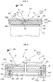
- Figure 1 is a vertical sectional view of a main portion of an internal mechanism of a wrist watch provided with a display unit structure for an electronic device corresponding to a first embodiment, in which the internal structure of the movement and the like are omitted.
- Figure 2 is a vertical sectional view of the display unit structure of the electronic device corresponding to the first embodiment.
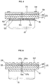
- Figure 3 is a vertical sectional view for explaining incident lights, reflecting lights, and transmitting lights relating to the display unit structure for the electronic device corresponding to the first embodiment.
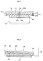
- Figure 4 is a vertical sectional view of a main portion of an internal mechanism of a wrist watch provided with a display unit structure for the electronic device corresponding to a second embodiment, in which the internal structure of the movement and the like are omitted.
- Figure 5 is a vertical sectional view showing the case where a watch with electro luminescence illumination incorporates a display unit structure for the electronic device corresponding to a third embodiment, in which the internal structure of the movement and the like are omitted.
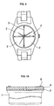
- Figure 6 is a vertical sectional view showing the case where an analogously indicative watch is incorporated in a display unit structure for the electronic device corresponding to a fourth embodiment, in which the internal structure of the movement and the like are omitted.
- Figure 7 is a vertical sectional view showing a display unit structure for the electronic device corresponding to a fifth embodiment, in which the internal structure of the movement and the like are omitted.
- Figure 8 is a vertical sectional view showing a display unit structure for the electronic device corresponding to a sixth embodiment, in which the internal structure of the movement and the like are omitted.
- Figure 9 is a top plan view of a main portion of a wrist watch provided with a conventional display unit structure for an electronic device.
- Figure 10 is a vertical sectional view of a conventional display unit structure for an electronic device.
- Figure 1 is a vertical sectional view of a main portion of an internal mechanism of a wrist watch provided with a display unit structure for the electronic device corresponding to a first embodiment
- Figure 2 is a vertical sectional view of the display unit structure for the electronic device corresponding to the first embodiment
- Figure 3 is a vertical sectional view for explaining incident lights, reflecting lights, and transmitting lights relating to the display unit structure for the electronic device corresponding to the first embodiment.
- the symbol 11 represents a case band/case body made of a metal or a synthetic resin, which is formed entirely from a cylindrical material with both ends open.
- An internal flange 12 having flange ends 12a, 12b and projecting in the radial direction of the case band/case body is integrated with the internal peripheral surface close to one of the openings (the upper opening in the Figures) of the case band/case body 11.
- the symbol 13 represents a glass made of glass or a synthetic resin and formed entirely from a transparent material of a circular shape in section.
- the glass 13 is installed inside the openings of the case band/case body so that its periphery is connected to the flange end 12a.
- the symbol 14 represents a case back made of a metal or a synthetic resin.
- the case back 14 is made of a non-transparent material and has a lid body 14a facing the other opening end (below in the Figures) of the case band/case body 11 and an engaging part 14b facing the inside of the other opening of the case band/case body 11.
- the case back 14 is installed in the other opening of the case band/case body 11 via a case back packing 10.
- the symbol 15 represents a movement for rotating the hands.
- the movement 15 consists of a step motor 15a, a decelerating train wheel (not shown), and the like and is held in the case band/case body 11 via a casing ring/casing frame 16.
- the symbol 17 represents a hand display unit for analogously indicating time.
- the hand display unit 17 includes a minute hand 18 and an hour hand 19 which are a hour hand and a minute hand respectively.
- the hand display unit 17 also includes a center wheel & pinion 20 and an hour wheel & pinion 21 which are respectively drive shafts for the minute hand 18 and the hour hand 19.
- the hands 18, 19 is rotated by driving the movement 15 to indicate time variably.
- the symbol 22 represents a solar cell for supplying power to the step motor 15a for driving the movement.
- the solar cell 22 is disposed between the flange end 12b of the inside flange 12 and the movement 15 and is connected to the movement 15 through a circuit substrate 23 equipped with a shaft insertion hole 23a.
- a shaft insertion hole 22a is provided opening both upward and down ward (in the axial direction of the wheels & pinions 20, 21).
- This solar cell 22 comprises a metal plate (not shown) formed of a SUS material or the like and an amorphous silicon layer (not shown) formed on the metal plate by vapor deposition or the like. Electric power generated in the solar cell is stored in a secondary battery or in a condenser (neither are shown) for a while.
- the symbol 24 represents a display mechanism including the hand display unit 17.
- the display mechanism 24 also includes a transmission-type reflecting plate 25 and a coating layer 26 and disposed at the side opposite to the movement on the solar cell 22.
- the transmission-type reflecting plate 25 is composed of a base layer 27 provided with a shaft insertion hole 27a communicating with the shaft insertion hole 22a in the center thereof and a hologram layer 28 provided with a shaft insertion hole 28a communicating with the shaft insertion hole 27a of the base layer 27.
- the transmission-type reflecting plate 25 is disposed at the side of the solar cell on the inner flange 12.
- the base layer 27 is placed at the side opposite to the movement on the solar cell 22 and is formed entirely from a transparent material made of a synthetic resin such as polyester or polyethylene terephthalate.
- the hologram layer 28 is formed of a volume type hologram (Lippman type hologram) and is laminated on the base layer 27 at the side of the hands. This hologram layer 28 is positioned at an inclination with respect to the surface 28b and back face 28c of the hologram layer. Also, the hologram layer 28 includes a virtual mirror plane 29 which, as shown in Figure 3, receives incident lights a and reflects only a light b1 having a predetermined wavelength in a specific direction.
- a virtual mirror plane 29 which, as shown in Figure 3, receives incident lights a and reflects only a light b1 having a predetermined wavelength in a specific direction.
- the hologram layer 28 is dependent on the wavelength and on the angle of reflection. Because of this, among the incident lights a from a light source 31, only the light b1 having a predetermined wavelength is reflected onto the virtual mirror plane 29 in a specific direction which never coincides with the directions of the paths of surface reflecting lights b2 and b3 which are each shown as a dotted line in Figure 3 and reach an observer 32. Also, the hologram layer 28 has light transmittability and hence, as the solid line shown in Figure 3, a light b4 of the wavelength other than the wavelength b1 penetrates the transmission-type reflecting plate 25 and reaches the solar cell 22.
- the coating layer 26 is provided with a shaft insertion hole 26a communicating with the shaft insertion hole 28a and is, as shown in Figures 2 and 3, attached to the hologram layer 28 at the hands side via an adhering layer 33.
- the coating layer 26 is formed entirely from a transparent or translucent material of a synthetic resin such as polycarbonate, acrylate, polyester, or the like.
- the light resistance and moisture resistance of the hologram layer 28 are increased and also the incorporation of the transmission-type reflecting plate 25 into the display mechanism 24 can be simply performed.
- An auxiliary display unit 34 (shown in Figure 1) including characters, patterns, marks, and the like, which constitutes a display unit other than the hand display unit 17 is formed on the hand side of the coating layer.
- the wheels & pinions 20, 21 are inserted into each shaft insertion hole for the coating layer 26, hologram layer 28, solar cell 22, and circuit substrate 23.
- the incident light a from the light source 31 penetrates the coating layer 26 and enters into the hologram layer 28, the light b1 having a predetermined wavelength is reflected on the virtual mirror plane 29.
- the observer 32 arranges the line of sight on the path of the light b1 having a predetermined wavelength, the light b1 having a predetermined wavelength reaches the observer 32 and is viewed as the light of a specific color.
- the observer 32 alters a sight point or the position of a watch, thereby to disarrange the line of sight on the path of the light b1 , the light b1 never reaches the observer 32.
- the solar cell 22 can be shielded so that it is not viewed from the hands side and also a desired color tone for the display unit (transmission-type reflecting plate 25) can be obtained, whereby the degree of freedom in designing the appearance can be increased.
- the light b4 of a wavelength other than the wavelength b1 penetrates the hologram layer 28 and base layer 27, reaches the solar cell 22, and is utilized for power generation of the solar cell 22.
- the generated power is supplied to the movement 15 via a condenser (not shown) to drive the movement 15 and thereby to rotate the wheels & pinions 20, 21.
- the incident light which enters the hologram layer 28 never scatters in all directions to result in an increase in the light entering the hologram layer 28, whereby the light utilization efficiency can be promoted.
- the observer 32 arranges the line of sight in the direction (the path of lights b1 ) which allows the hand display unit 17 to be viewed so that the time can be read.
- Figure 4 is a vertical sectional view of a main portion of the internal mechanism of a wrist watch provided with a display unit structure for an electronic device corresponding to a second embodiment, in which the same or equivalent materials as those in Figure 1 are represented by the same symbols (excluding the solar cell), therefore detailed descriptions are omitted and, also, in Figure 4, the internal structure of the movement and the like are omitted.
- a solar cell represented by the symbol 41 is similar to the solar cell 22 in the first embodiment and includes a metal plate 42 formed of a SUS material or the like and of an amorphous silicon layer 43 formed on the metal plate 42 by vapor deposition or the like.
- the solar cell 41 is supported in a case band/case body 11 via a casing ring/casing frame 16.
- An electrode 41a connecting with a terminal 23a of a circuit substrate 23 via a compressed coil spring 44 is formed in the solar cell 41.
- Figure 5 is a vertical sectional view showing the case where a watch with electro luminescence illumination incorporated in a display unit structure for an electronic device corresponding to a third embodiment, in which the same or equivalent materials as those in Figures 1 and 2 are represented by the same symbols, thereby detailed descriptions are omitted. Also, in Figure 5, the internal structure of the movement and the like are omitted.
- the symbol 51 represents an electro luminescence panel. Wheels & pinions 20, 21 (shown in Figure 1) are inserted into the center of the electro luminescence panel 51 which is disposed between a movement 15 and a transmission-type reflecting plate 25.
- the electro luminescence panel 51 includes upper and lower circular transparent sections 52, 53 made of a synthetic resin, which face each other at a specific interval in a vertical direction (the axial direction of the wheels & pinion s 20, 21), inner and outer cylindrical seal materials 54, 55, which extend inner and outer peripheries of the transparent materials 52, 53 respectively, and a fluorescent body 56 of zinc sulfate or the like which is imposed between both of the sealing materials 54, 55 and both of the transparent sections 52, 53.
- the electro luminescence panel 51 emits light by the application of an a.c. voltage, whereby a hand display unit 17 is illuminated.
- the electro luminescence panel 51 can be shielded so that it is not viewed from the hands side. Also a desired color tone for the display unit (transmission-type reflecting plate 25) can be obtained, whereby the degree of freedom in designing the appearance can be increased.
- Figure 6 is a vertical sectional view showing the case where an analogously indicating watch is incorporated with a display unit structure for an electronic device corresponding to a fourth embodiment, in which the same or equivalent materials as those in Figures 1 and 2 are represented by the same symbols, therefore detailed descriptions are omitted. Also, in Figure 6, the internal structure of the movement and the like are omitted.
- the symbol 61 represents a metal plate including a shaft insertion hole 61a into which wheels & pinion s 20, 21 are inserted.
- the metal plate 61 is disposed between a movement 15 and a transmission-type reflecting plate 25.
- an auxiliary display unit 62 including characters, patterns, marks, and the like is integrally formed with and over the entire surface of a coating layer 26.
- the internal structure of a watch can be shielded so that it is not viewed from the hands side. Also, a desired color tone for the display unit (transmission-type reflecting plate 25) can be obtained, whereby the degree of freedom in designing the appearance can be increased.
- Figure 7 is a vertical sectional view showing a display unit structure for an electronic device corresponding to a fifth embodiment, in which the same or equivalent materials as those in Figure 6 are represented by the same symbols, therefore detailed descriptions are omitted.
- the symbol 71 represents a coating layer which constitutes part of a display mechanism 24.
- the coating layer 71 is provided with a shaft insertion hole 71a communicating with a shaft insertion hole 28a and is attached to a hologram layer 28 at the hands side via an adhering layer 33.
- the coating layer 71 is formed of the same transparent material as the coating layer 26 in the first embodiment or of a translucent material.
- a circular wall 71b covering the outer periphery of a transparent reflecting plate 25 is integrated with the outer periphery of the coating layer 71 at the side opposite to the hands (below in Figure 7). The light resistance and moisture resistance of a hologram layer 28 are further increased.
- a metal plate 61 and the like can be shielded so that it is not viewed from the outside. Also, a desired color tone for the display unit (transmission-type reflecting plate 25) can be obtained, whereby the degree of freedom in designing the appearance can be increased.
- the display unit structure for an electronic device corresponding to the present invention can be used for display unit structures for various electronic devices such as electronic watches, electronic calculators, portable radios, and the like.
Landscapes
- Physics & Mathematics (AREA)
- General Physics & Mathematics (AREA)
- Engineering & Computer Science (AREA)
- Power Engineering (AREA)
- Electric Clocks (AREA)
- Electromechanical Clocks (AREA)
Applications Claiming Priority (7)
| Application Number | Priority Date | Filing Date | Title |
|---|---|---|---|
| JP29513995 | 1995-11-14 | ||
| JP295139/95 | 1995-11-14 | ||
| JP7295139A JPH09138287A (ja) | 1995-11-14 | 1995-11-14 | 太陽電池付き電子機器 |
| JP10702196 | 1996-04-26 | ||
| JP107021/96 | 1996-04-26 | ||
| JP10702196A JP3847834B2 (ja) | 1996-04-26 | 1996-04-26 | 電子時計 |
| PCT/JP1996/003317 WO1997018500A1 (fr) | 1995-11-14 | 1996-11-12 | Structure d'unite d'affichage destinee a un dispositif electronique |
Publications (3)
| Publication Number | Publication Date |
|---|---|
| EP0803784A1 true EP0803784A1 (fr) | 1997-10-29 |
| EP0803784A4 EP0803784A4 (fr) | 1998-04-15 |
| EP0803784B1 EP0803784B1 (fr) | 2002-03-13 |
Family
ID=26447096
Family Applications (1)
| Application Number | Title | Priority Date | Filing Date |
|---|---|---|---|
| EP96937563A Expired - Lifetime EP0803784B1 (fr) | 1995-11-14 | 1996-11-12 | Structure d'unite d'affichage destinee a un dispositif electronique |
Country Status (4)
| Country | Link |
|---|---|
| US (1) | US5841738A (fr) |
| EP (1) | EP0803784B1 (fr) |
| DE (1) | DE69619796T2 (fr) |
| WO (1) | WO1997018500A1 (fr) |
Cited By (2)
| Publication number | Priority date | Publication date | Assignee | Title |
|---|---|---|---|---|
| EP1099722A3 (fr) * | 1999-11-12 | 2001-08-16 | Junghans Uhren GmbH | Article en matière plastique ayant un aspect métallique, en particulier boitiers de montre bracelet radio |
| EP1331529A4 (fr) * | 2000-11-01 | 2006-01-18 | Kawaguchiko Seimitsu Kk | Cadran d'horlogerie et procede de production associe |
Families Citing this family (21)
| Publication number | Priority date | Publication date | Assignee | Title |
|---|---|---|---|---|
| KR100594784B1 (ko) * | 1996-03-08 | 2007-05-14 | 시티즌 도케이 가부시키가이샤 | 시계용표시판 |
| US5880796A (en) * | 1996-07-12 | 1999-03-09 | Casio Computer Co., Ltd. | Display device with display plate having metal upper suface including narrow outgoing opening for emitting light from light emitting member |
| WO1998010327A1 (fr) * | 1996-09-02 | 1998-03-12 | Seiko Epson Corporation | Panneau a cristaux liquides et appareil electronique faisant appel a ce panneau |
| EP0985985B1 (fr) * | 1997-05-22 | 2003-03-26 | Citizen Watch Co. Ltd. | Cadran de dispositifs d'horlogerie et procede de fabrication |
| US6624858B2 (en) * | 1997-08-01 | 2003-09-23 | Citizen Watch Co., Ltd. | Light scattering type liquid crystal display panel for timepiece |
| US7604080B2 (en) * | 1997-12-17 | 2009-10-20 | Automotive Technologies International, Inc. | Rear impact occupant protection apparatus and method |
| US6450407B1 (en) | 1998-04-17 | 2002-09-17 | Viztec, Inc. | Chip card rebate system |
| US7854684B1 (en) | 1998-06-24 | 2010-12-21 | Samsung Electronics Co., Ltd. | Wearable device |
| DE69926912T2 (de) * | 1998-12-22 | 2006-02-09 | Citizen Watch Co., Ltd., Nishitokyo | Zeitmessgerät |
| JP3106206B1 (ja) * | 1999-05-27 | 2000-11-06 | 新生化学工業株式会社 | 情報記憶媒体の携帯具 |
| WO2001037350A1 (fr) * | 1999-11-12 | 2001-05-25 | Citizen Watch Co., Ltd. | Dispositif d'affichage d'un appareil electronique equipe d'une pile solaire |
| US7206044B2 (en) * | 2001-10-31 | 2007-04-17 | Motorola, Inc. | Display and solar cell device |
| ATE350693T1 (de) * | 2004-04-24 | 2007-01-15 | Winwatch Sa | Verfahren zum integrieren mindestens eines elektronischen moduls in oder auf dem glas einer uhr |
| EP1852754B1 (fr) * | 2005-02-09 | 2012-05-30 | Citizen Holdings Co., Ltd. | Plaque d'affichage pour appareil à cellule solaire |
| JP6056167B2 (ja) * | 2012-03-28 | 2017-01-11 | セイコーエプソン株式会社 | 時計 |
| US9834136B2 (en) | 2012-06-19 | 2017-12-05 | Ford Global Technologies, Llc | Illuminated chromatic emblem assembly |
| US10011215B2 (en) | 2012-06-19 | 2018-07-03 | Ford Global Technologies, Llc | Illuminated chromatic emblem assembly with micro LEDs |
| US9481296B2 (en) | 2012-06-19 | 2016-11-01 | Ford Global Technologies, Llc | Illuminated chromatic emblem assembly with micro LEDS |
| US8752989B2 (en) | 2012-06-19 | 2014-06-17 | Ford Global Technologies, Llc | Illuminated chromatic vehicle emblem |
| WO2014123818A1 (fr) * | 2013-02-07 | 2014-08-14 | 3M Innovative Properties Company | Dispositif d'affichage de papier électronique auto-alimenté |
| USD815971S1 (en) * | 2016-05-09 | 2018-04-24 | Avraham Goldstein | Watch face |
Family Cites Families (10)
| Publication number | Priority date | Publication date | Assignee | Title |
|---|---|---|---|---|
| JPS5875085A (ja) * | 1981-10-30 | 1983-05-06 | Seiko Epson Corp | 時計用文字板 |
| EP0247055A1 (fr) * | 1985-03-07 | 1987-12-02 | ROBINSON, Anthony John Benbow | Moyens indicateurs analogiques holographiques |
| JPS6219786A (ja) * | 1985-07-18 | 1987-01-28 | Dainippon Printing Co Ltd | ホログラム付き時計文字板 |
| JPS62165590A (ja) * | 1986-01-17 | 1987-07-22 | Shin Meiwa Ind Co Ltd | スクロ−ル形流体機械 |
| JPS62165590U (fr) * | 1986-04-11 | 1987-10-21 | ||
| JP2622677B2 (ja) * | 1986-07-17 | 1997-06-18 | 大日本印刷株式会社 | 太陽電池及び太陽電池を使用した電気製品 |
| DE3722012A1 (de) * | 1987-07-03 | 1989-01-12 | Hartmut Gunter Gericke | Uhr mit einem zifferblatt |
| JPH0585784A (ja) * | 1991-09-27 | 1993-04-06 | Asahi Glass Co Ltd | ホログラム封入合せガラス |
| JPH05333758A (ja) * | 1992-06-02 | 1993-12-17 | Toyobo Co Ltd | 3次元動画ディスプレイ装置 |
| US5586089A (en) * | 1994-03-18 | 1996-12-17 | Mcgarvey; John D. | Rotational moire timepiece |
-
1996
- 1996-11-12 EP EP96937563A patent/EP0803784B1/fr not_active Expired - Lifetime
- 1996-11-12 WO PCT/JP1996/003317 patent/WO1997018500A1/fr not_active Ceased
- 1996-11-12 US US08/860,858 patent/US5841738A/en not_active Expired - Fee Related
- 1996-11-12 DE DE69619796T patent/DE69619796T2/de not_active Expired - Fee Related
Cited By (4)
| Publication number | Priority date | Publication date | Assignee | Title |
|---|---|---|---|---|
| EP1099722A3 (fr) * | 1999-11-12 | 2001-08-16 | Junghans Uhren GmbH | Article en matière plastique ayant un aspect métallique, en particulier boitiers de montre bracelet radio |
| EP1331529A4 (fr) * | 2000-11-01 | 2006-01-18 | Kawaguchiko Seimitsu Kk | Cadran d'horlogerie et procede de production associe |
| US7242641B2 (en) | 2000-11-01 | 2007-07-10 | Citizen Seimitus Co., Ltd. | Timepiece dial and production method therefor |
| CN100432867C (zh) * | 2000-11-01 | 2008-11-12 | 西铁城精密株式会社 | 钟表用文字板 |
Also Published As
| Publication number | Publication date |
|---|---|
| WO1997018500A1 (fr) | 1997-05-22 |
| EP0803784B1 (fr) | 2002-03-13 |
| DE69619796T2 (de) | 2002-10-31 |
| DE69619796D1 (de) | 2002-04-18 |
| US5841738A (en) | 1998-11-24 |
| EP0803784A4 (fr) | 1998-04-15 |
Similar Documents
| Publication | Publication Date | Title |
|---|---|---|
| EP0803784B1 (fr) | Structure d'unite d'affichage destinee a un dispositif electronique | |
| US6208591B1 (en) | Luminescent device, timepiece, electronic apparatus and method for manufacturing luminescent device | |
| KR100334843B1 (ko) | 시계 | |
| US8787120B2 (en) | Exterior element for a wristwatch | |
| JPWO1999004322A1 (ja) | 時 計 | |
| KR100234636B1 (ko) | 광 방출장치를 갖춘 전자용품 | |
| US5881024A (en) | Combination display timepiece equipped with el illumination | |
| JP3637307B2 (ja) | 発電機能付き時計 | |
| JPH0990059A (ja) | 時計文字板構造 | |
| KR20000064299A (ko) | 액정 패널 및 그것을 이용한 전자기기 | |
| JP3497972B2 (ja) | 時計用文字板 | |
| JP2004198681A (ja) | 照明装置および電子機器 | |
| JP3847834B2 (ja) | 電子時計 | |
| JP3524588B2 (ja) | エレクトロルミネッセンス素子付き太陽電池時計 | |
| JP2003186429A (ja) | 発光装置および電子機器 | |
| JP4685435B2 (ja) | 太陽電池付時計 | |
| US12436501B2 (en) | Solar watch | |
| JP4025314B2 (ja) | 発電機能付き表示装置 | |
| JPH0516497Y2 (fr) | ||
| JPH0963765A (ja) | バックライト付き表示装置およびそれを備えた電子機器 | |
| JP2003162240A (ja) | 発光装置および電子機器 | |
| JP4025315B2 (ja) | 表示装置 | |
| JP3745087B2 (ja) | ソーラー時計用表示板構造 | |
| KR19980080697A (ko) | 솔라시계용 문자판 및 솔라시계 | |
| JP2008122161A (ja) | 時計用文字板、時計、および装飾用化粧板 |
Legal Events
| Date | Code | Title | Description |
|---|---|---|---|
| PUAI | Public reference made under article 153(3) epc to a published international application that has entered the european phase |
Free format text: ORIGINAL CODE: 0009012 |
|
| AK | Designated contracting states |
Kind code of ref document: A1 Designated state(s): DE GB IT |
|
| 17P | Request for examination filed |
Effective date: 19971031 |
|
| A4 | Supplementary search report drawn up and despatched | ||
| AK | Designated contracting states |
Kind code of ref document: A4 Designated state(s): DE GB IT |
|
| 17Q | First examination report despatched |
Effective date: 19991123 |
|
| GRAG | Despatch of communication of intention to grant |
Free format text: ORIGINAL CODE: EPIDOS AGRA |
|
| RAP1 | Party data changed (applicant data changed or rights of an application transferred) |
Owner name: CITIZEN WATCH CO. LTD. |
|
| GRAG | Despatch of communication of intention to grant |
Free format text: ORIGINAL CODE: EPIDOS AGRA |
|
| GRAG | Despatch of communication of intention to grant |
Free format text: ORIGINAL CODE: EPIDOS AGRA |
|
| GRAH | Despatch of communication of intention to grant a patent |
Free format text: ORIGINAL CODE: EPIDOS IGRA |
|
| GRAH | Despatch of communication of intention to grant a patent |
Free format text: ORIGINAL CODE: EPIDOS IGRA |
|
| REG | Reference to a national code |
Ref country code: GB Ref legal event code: IF02 |
|
| GRAA | (expected) grant |
Free format text: ORIGINAL CODE: 0009210 |
|
| AK | Designated contracting states |
Kind code of ref document: B1 Designated state(s): DE GB IT |
|
| REF | Corresponds to: |
Ref document number: 69619796 Country of ref document: DE Date of ref document: 20020418 |
|
| PLBE | No opposition filed within time limit |
Free format text: ORIGINAL CODE: 0009261 |
|
| STAA | Information on the status of an ep patent application or granted ep patent |
Free format text: STATUS: NO OPPOSITION FILED WITHIN TIME LIMIT |
|
| 26N | No opposition filed |
Effective date: 20021216 |
|
| PGFP | Annual fee paid to national office [announced via postgrant information from national office to epo] |
Ref country code: DE Payment date: 20081107 Year of fee payment: 13 |
|
| PGFP | Annual fee paid to national office [announced via postgrant information from national office to epo] |
Ref country code: IT Payment date: 20081126 Year of fee payment: 13 |
|
| PGFP | Annual fee paid to national office [announced via postgrant information from national office to epo] |
Ref country code: GB Payment date: 20081112 Year of fee payment: 13 |
|
| GBPC | Gb: european patent ceased through non-payment of renewal fee |
Effective date: 20091112 |
|
| PG25 | Lapsed in a contracting state [announced via postgrant information from national office to epo] |
Ref country code: DE Free format text: LAPSE BECAUSE OF NON-PAYMENT OF DUE FEES Effective date: 20100601 |
|
| PG25 | Lapsed in a contracting state [announced via postgrant information from national office to epo] |
Ref country code: GB Free format text: LAPSE BECAUSE OF NON-PAYMENT OF DUE FEES Effective date: 20091112 |
|
| PG25 | Lapsed in a contracting state [announced via postgrant information from national office to epo] |
Ref country code: IT Free format text: LAPSE BECAUSE OF NON-PAYMENT OF DUE FEES Effective date: 20091112 |