EP0803720B1 - Station de mesure du balourd - Google Patents
Station de mesure du balourd Download PDFInfo
- Publication number
- EP0803720B1 EP0803720B1 EP97102023A EP97102023A EP0803720B1 EP 0803720 B1 EP0803720 B1 EP 0803720B1 EP 97102023 A EP97102023 A EP 97102023A EP 97102023 A EP97102023 A EP 97102023A EP 0803720 B1 EP0803720 B1 EP 0803720B1
- Authority
- EP
- European Patent Office
- Prior art keywords
- bearing
- crankshaft
- devices
- station according
- unbalance
- Prior art date
- Legal status (The legal status is an assumption and is not a legal conclusion. Google has not performed a legal analysis and makes no representation as to the accuracy of the status listed.)
- Expired - Lifetime
Links
- 230000005489 elastic deformation Effects 0.000 claims description 5
- 238000003860 storage Methods 0.000 description 60
- 238000005259 measurement Methods 0.000 description 6
- 238000000034 method Methods 0.000 description 6
- 230000008569 process Effects 0.000 description 6
- 230000005540 biological transmission Effects 0.000 description 4
- 230000004913 activation Effects 0.000 description 3
- 238000009420 retrofitting Methods 0.000 description 3
- 230000003213 activating effect Effects 0.000 description 2
- 230000009286 beneficial effect Effects 0.000 description 2
- 238000006243 chemical reaction Methods 0.000 description 2
- 238000005553 drilling Methods 0.000 description 2
- 229910000831 Steel Inorganic materials 0.000 description 1
- 229910052782 aluminium Inorganic materials 0.000 description 1
- XAGFODPZIPBFFR-UHFFFAOYSA-N aluminium Chemical compound [Al] XAGFODPZIPBFFR-UHFFFAOYSA-N 0.000 description 1
- 230000008859 change Effects 0.000 description 1
- 230000009849 deactivation Effects 0.000 description 1
- 230000006866 deterioration Effects 0.000 description 1
- 238000003754 machining Methods 0.000 description 1
- 238000004519 manufacturing process Methods 0.000 description 1
- 239000000463 material Substances 0.000 description 1
- 230000007246 mechanism Effects 0.000 description 1
- 229910052751 metal Inorganic materials 0.000 description 1
- 239000002184 metal Substances 0.000 description 1
- 238000003801 milling Methods 0.000 description 1
- 230000003534 oscillatory effect Effects 0.000 description 1
- 239000010959 steel Substances 0.000 description 1
- 238000003466 welding Methods 0.000 description 1
Images


Classifications
-
- G—PHYSICS
- G01—MEASURING; TESTING
- G01M—TESTING STATIC OR DYNAMIC BALANCE OF MACHINES OR STRUCTURES; TESTING OF STRUCTURES OR APPARATUS, NOT OTHERWISE PROVIDED FOR
- G01M1/00—Testing static or dynamic balance of machines or structures
- G01M1/14—Determining imbalance
- G01M1/16—Determining imbalance by oscillating or rotating the body to be tested
- G01M1/24—Performing balancing on elastic shafts, e.g. for crankshafts
Definitions
- the invention relates to an unbalance measuring station for determination the unbalance of crankshafts with several bearings, with a device for driving the crankshaft, with storage facilities supported on a swing bridge rotatable bearing of the crankshaft at two bearing points of the Crankshaft and with devices for detecting the unbalance vibrations.
- Another unbalance measuring device with three bearing devices JP 55 147327 A can be found for the crankshaft.
- An unbalance measuring station is known from DE-43 34 244 A1, in which the crankshaft to be balanced in two bearing devices is rotatably mounted. Both storage facilities are supported on a swing bridge and have bearing rollers as Bearing elements for mounting the crankshaft.
- the crankshaft is from one on a spigot of a storage facility rotatably mounted drive device with a crank pin the crankshaft cooperates, driven; this storage facility is firmly connected to the swing bridge.
- the second bearing device is axially on the swing bridge for the purpose Adaptable to crankshafts of different lengths and in the adjusted position with a mounting foot on the Swinging bridge attached.
- Retrofitting the unbalance measuring station to another type of crankshaft, for example four, five or six-cylinder crankshafts is by moving the second storage facility possible, but cumbersome and time-consuming and therefore too expensive in series production. Also after retrofitting would be curvature-related Influences cannot always be avoided, as with crankshafts principally existing curvature along its extent, which can be greater than the permissible balancing tolerance, in generally not by selecting the optimal ones for the crankshafts, bearing points that take the curvature into account are negligible can be made.
- the invention is therefore based on the object of an unbalance measuring station or an unbalance measuring and compensation station create with which different crankshafts without elaborate Conversion campaigns also optimal in terms of their curvature stored and measured or measured and balanced can.
- SU-1411592-A1 is an unbalance measuring station with two Pairs of storage facilities supported on a swing bridge known for the crankshaft, but is only one of them Storage facility pairs for rotatable storage in the form provided by end bearing tips while the other Storage facility pair for temporary storage of the rotating crankshaft at two crankshaft bearings to facilitate storage between the two Bearing tips.
- One of the bearing tips Bearing devices can be moved axially around both bearing tips when storing in the front tapered mounting holes to bring the crankshaft. An upgrade on different crankshafts is not provided.
- SU 1 769 030 A discloses a balancing machine for crankshafts with a machine bed, a device for the drive the crankshaft and bearing devices for rotatable storage the crankshaft supported on a swing bridge are.
- Storage facilities are two additional storage facilities provided, however, on the arms of one on the machine bed attached actuator attached and can be actuated by this and are provided as counterholders are.
- the machine can be converted for different purposes Crankshaft types or a displaceability of the storage facilities in the longitudinal direction of the crankshaft and thus convertibility different crankshaft types are not considered.
- US-A-3 090 237 discloses a lathe used for balancing of rotors with two storage stands as storage facilities can be converted for the rotor to be balanced.
- Each of these two storage stands has a lower area with which he can be placed anywhere along the extension of the Machine bed is attachable and an upper area with the rotors of different diameters in alignment with the
- the axis of rotation of the lathe can be supported via bearing rollers.
- the bearing rollers can be moved using a scissor mechanism to different heights and horizontal distances Set the rotor diameter.
- the elastic deformations to the radial Relocation of the storage facilities can be done by charging be effected via an eccentric device; Twists the Eccentric devices facilitate the automation of activation / deactivation various storage facilities.
- On a single control shaft can be used for easy automation easily the required number of eccentric devices arrange so that different about the rotation of the control shaft Combinations of storage facilities activated or can be deactivated.
- a compact design results when arranging the control shaft between the two longitudinal spars the swing bridge.
- An embodiment is also advantageous in which only one below the number of crankshaft bearings Number of storage facilities is provided.
- the number of Storage facilities are considered taking into account the in Question coming crankshaft types set.
- Fig. 1 is an unbalance measuring station for determining the Imbalance of crankshafts, in the illustrated example of a crankshaft (10) for a six-cylinder engine with bearings 1 to 7, shown schematically.
- the unbalance measuring station has a swing bridge 11, which Springs 12 supported on a machine bed, not shown is.
- the swing bridge 11 consists essentially of two longitudinal spars 13, 14 and crossbeams over which the longitudinal spars 13, 14 are connected at 14 ends.
- On one crossbar is the drive device for the crankshaft 10 arranged, which is rotatably arranged on a spindle 16 has driver 17 driven by a belt drive 15, which interacts with the flange plate 18 of the crankshaft 10.
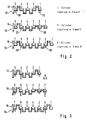
- the unbalance measuring station is used to determine the unbalance of different ones Provided crankshafts, for example of four, Five- or six-cylinder crank shafts, each like from Fig. 2 can be seen, with two type-specific, optimal bearings are stored, each symbolized by triangles 20 Storage facilities are assigned.
- the five-cylinder crankshaft is optimized with the bearing points 5 and 2 stored (middle picture of Fig. 2).
- the six-cylinder crankshaft is optimized with the bearings 6 and 2 stored (bottom image in Fig. 2).
- the bearing 5 corresponds to Four-cylinder crankshaft of the flange 18 adjacent Depository.
- End bearing 1 of the four-cylinder crankshaft and bearing 2 of the five-cylinder crankshaft have the same axial distance from the flange disc 18, the axial position of the crankshafts in the unbalance measuring station certainly.
- crankshaft types Fr-cylinder, five-cylinder, six-cylinder crankshafts
- partially matching bearings are provided, while two are in their axial position with respect to the flange disc 18 bearing locations that match all three crankshaft types usually not used. This makes it possible when determining the unbalance of various crankshafts with a total to work only four different storage facilities.
- FIG. 3 which in its schematic representation of the Fig. 2 starts, the storage conditions for each other Four-, five- and six-cylinder short shafts are shown.
- the Bearing devices in FIG. 3 are the same as in FIG. 2 Symbolizes triangles.
- the top picture shows that two of the four bearing devices are active in unbalance measurements are, namely the storage facilities assigned to the storage locations 5 and 1, while the storage facility 4 associated storage facility is inactive.
- the storage facility is on the far right no crankshaft bearing point assigned to this crankshaft, so it doesn't matter if they activate you or inactivated state.
- the bearing elements are at a distance to the bearing surfaces at the crankshaft bearings, while in the activated state the crankshaft with the bearing surfaces their bearing points rests on the bearing elements.
- the flange disk 18 is adjacent Bearing device for bearing 7 of a six-cylinder crankshaft 10 inactive for the storage location 6 active, inactive for depository 3 and that for the depository 2 active.
- crankshaft shown in Fig. 1 with Storage facilities correspond to the basic representation in bottom image of FIG. 3.
- the bearing devices 30 from FIG. 1 have seen in the axial direction, the embodiment shown in Fig. 4 on.
- the bearing device 30 is slidable on the two Longitudinal bars 13, 14 of the swing bridge 11 out and in a certain axial position fixable.
- the bearing device 30 has two bearing elements in the form of rotatably mounted rollers 21, 22 on which the crankshaft 10 can be supported. Instead of the Storage in a roller set 21, 22 can be stored in a single or multi-part plain bearings can be provided.
- the bearing device 30 can be in an active state in which the Rollers 21, 22 support the bearing surface of the crankshaft 10, in an inactive state in which the rollers 21, 22 have a slight Have a distance of the order of one millimeter, can be switched.
- this small adjustment path due to elastic deformation of a Adjustment area 23 of the bridge-shaped bearing device 30 realized.
- the storage facility In this case, 30 is preferably made of a tabular one Semi-finished metal e.g. B. formed from steel or aluminum.
- the Adjustment area 23 is formed by parting lines 24 to 28 Spring elements 31 to 34 with the base region 29 of the bearing device 30 connected, the spring elements 31, 32 and 33, 34 symmetrical on both sides of the line of symmetry between the two Longitudinal beam bearings are arranged.
- the adjustment range 23 can with elastic deformation of the spring elements 31 to 34 away from the base region 29 and moved towards it again.
- An eccentric device 40 is provided as the adjusting device a tab 41 is provided, one end of which is rotatable about a Roller bearing 42 in the base region 29 of the bridge-shaped bearing device 30 between the longitudinal beam bearing points are mounted on an eccentric element 43 and the other end beyond the parting lines 24 to 28 pivotable in a bearing pin 44 of the adjustment area 23 is stored.
- the eccentric element 43 is located on a control shaft 45 and moves over the tab when the control shaft 45 is rotated 41 the resiliently mounted adjustment area 23 of the bearing device 30.
- the eccentric element 43 is disc-shaped and on an area of the control shaft 45 with a square profile.
- Stop devices 50 are also located on the bearing device 30 Course of the vibration transmission path from the bearing rollers 21 or 22 provided for the swing bridge 11, with which the elastic deformable spring areas 31 to 34 according to their Activation deformation to eliminate unwanted Elasticities are bridged.
- the anchor devices 50 are located symmetrically to the left and right of the line of symmetry in the transmission path between the respective bearing roller 21 or 23 and the L Lucasspolm bearing.
- the left 24 or right Parting line 25 is arranged so that stop surfaces 51, 52 of the Adjustment area 23 against stop surfaces 53, 54 of the base area 29 can be applied and thereby the elastic spring areas 31 to 34 are bridged.
- the two parting lines 24, 25 form an undercut, followed by a vertical and a horizontal section that is at a distance from the Line of symmetry ends.
- the horizontal section encompasses a U-shaped parting line 26 and 27, respectively U-shaped parting lines 26, 27 via a further parting line 28 are interconnected.
- the horizontal section encompasses a U-shaped parting line 26 and 27, respectively U-shaped parting lines 26, 27 via a further parting line 28 are interconnected.
- These parting line arrangements are two leaf spring elements on both sides of the line of symmetry 31, 32 and 33, 34 formed in the bearing device 30, the form an elastically deformable area.
- the control shaft 45 extends between the longitudinal spars 13, 14 and is provided with eccentric elements 43 that everyone Bearing device or bearing bridge 30 an eccentric device 43 is assigned and by rotating the control shaft 45 each two bearing devices 30 as shown schematically in FIG. 3 can be activated. Based on the numbering only in the lower picture of Fig. 3 and the corresponding numbering in Fig. 1 that means, optionally activating the numbers 2 + 6 (lower picture), 3 + 6 (middle picture with numbers from the bottom picture) and 3 + 7 (top picture).
Landscapes
- Physics & Mathematics (AREA)
- General Physics & Mathematics (AREA)
- Testing Of Balance (AREA)
- Shafts, Cranks, Connecting Bars, And Related Bearings (AREA)
Claims (16)
- Poste de mesure de balourd pour déterminer le balourd de plusieurs vilebrequins (10) présentant des emplacements de palier avec un dispositif (15, 17) pour l'entraínement du vilebrequin (10), comportant des agencements de palier (30), soutenus par un pont oscillant 11, pour supporter en rotation le vilebrequin (10), et comportant un dispositif de détection des oscillations dues au balourd, caractérisé en ce que sur le pont oscillant (11) sont soutenus plus de deux agencements de palier (30) pour supporter en rotation le vilebrequin (10), et il est prévu un dispositif au moyen duquel on peut faire varier la distance radiale entre des emplacements de palier du vilebrequin (10) et des agencements de palier (30) correspondants du poste de mesure de balourd pour supporter en rotation le vilebrequin (10) dans chacun des agencements de palier (30) existants, deux emplacements de palier pour supporter en rotation le vilebrequin (10) pouvant être choisis en fonction du type du vilebrequin parmi les emplacements de palier, et le vilebrequin (10) étant soutenu en rotation uniquement avec les emplacements de palier choisis sur les agencements de palier (30) correspondants.
- Poste de mesure de balourd et d'équilibrage pour compenser le balourd de plusieurs vilebrequins (10) présentant des emplacements de palier, comportant un dispositif (15, 17) pour l'entraínement du vilebrequin (10), comportant des agencements de palier (30), soutenus par un pont oscillant 11, pour supporter en rotation le vilebrequin (10), et comportant un dispositif de détection des oscillations dues au balourd, et comportant un dispositif pour compenser un balourd, caractérisé en ce que sur le pont oscillant (11) sont soutenus plus de deux agencements de palier (30) pour supporter en rotation le vilebrequin (10), et il est prévu un dispositif au moyen duquel on peut faire varier la distance radiale entre des emplacements de palier du vilebrequin (10) et des agencements de palier (30) correspondants du poste de mesure de balourd pour supporter en rotation le vilebrequin (10) dans chacun des agencements de palier (30) existants, pour un cycle de mesure du balourd deux emplacements de palier du vilebrequin (10) pouvant être choisis en fonction du type du vilebrequin parmi les emplacements de palier et le vilebrequin (10) n'étant soutenu en rotation, pendant le cycle de mesure du balourd, qu'avec les emplacements de palier choisis sur les agencements de palier (30) correspondants, tandis que le vilebrequin (10) non tournant est soutenu, pendant une opération de compensation du balourd, sur des emplacements de palier choisis et des agencements de palier (30) correspondants.
- Poste selon l'une ou les deux revendications précédentes, caractérisé en ce qu'au moins un agencement de palier (30) comporte plusieurs éléments de palier.
- Poste selon la revendication 3, caractérisé en ce que chaque agencement de palier (30) ou au moins un élément de palier de l'agencement de palier est déplaçable dans la direction radiale de manière mécanique, électrique ou actionnée par un fluide sous pression.
- Poste selon une ou plusieurs des revendications précédentes, caractérisé en ce que pour le déplacement dans la direction radiale, au moins une partie (31-34) de chaque agencement de palier (30) est déformable élastiquement.
- Poste selon la revendication 5, caractérisé en ce que pour la déformation élastique les agencement de palier (30) respectifs sont sollicités de manière mécanique, électrique ou actionnés par un fluide sous pression.
- Poste selon la revendication 6, caractérisé en ce qu'il est prévu un dispositif à excentrique (40-44) pour la sollicitation.
- Poste selon la revendication 7, caractérisé en ce que chaque agencement de palier comporte un dispositif à excentrique (40-44) associé.
- Poste selon la revendication 8, caractérisé en ce que les dispositifs à excentrique (40-44) sont disposés sur un arbre de commande (45) commun.
- Poste selon la revendication 9, caractérisé en ce que l'arbre de commande est conformé en arbre à cames.
- Poste selon une ou les deux revendications 9 et 10, caractérisé en ce que l'arbre de commande (45) comporte des parties cylindriques (43) disposées excentrées sur lesquelles sont disposées des attaches (41) fixées pivotantes sur l'agencement de palier respectif, de préférence par l'intermédiaire de roulements à billes.
- Poste selon une ou plusieurs des revendications 9 à 11 précédentes, caractérisé en ce que les ponts de palier sont disposés sur deux éléments en barre formant les longerons (13, 14) du pont oscillant (11), et en ce que l'arbre de commande (45) est disposé entre les éléments en barre.
- Poste selon une ou plusieurs des revendications 5 à 12 précédentes, caractérisé en ce que chaque agencement de palier comporte des dispositifs de butée (50) au moyen desquels la zone (31-34) déformable élastiquement de l'agencement de palier peut être franchie après déformation.
- Poste selon la revendication 13, caractérisé en ce que les dispositifs de butée (50) sont prévus dans la zone entre l'élément de palier sous la forme par exemple d'un palier de glissement ou palier de roulement (21, 22) et les longerons (13, 14).
- Poste selon une ou plusieurs des revendications 5 à 14 précédentes, caractérisé en ce que la zone déformable élastiquement comporte des éléments à ressort bistables.
- Poste selon une ou plusieurs des revendications précédentes, caractérisé en ce que le nombre d'agencements de palier (30) est supérieur à deux mais inférieur au nombre d'emplacement de palier sur le vilebrequin (10).
Applications Claiming Priority (2)
| Application Number | Priority Date | Filing Date | Title |
|---|---|---|---|
| DE19615891 | 1996-04-23 | ||
| DE19615891A DE19615891A1 (de) | 1996-04-23 | 1996-04-23 | Unwuchtmeßstation |
Publications (3)
| Publication Number | Publication Date |
|---|---|
| EP0803720A2 EP0803720A2 (fr) | 1997-10-29 |
| EP0803720A3 EP0803720A3 (fr) | 1999-01-07 |
| EP0803720B1 true EP0803720B1 (fr) | 2002-08-28 |
Family
ID=7792019
Family Applications (1)
| Application Number | Title | Priority Date | Filing Date |
|---|---|---|---|
| EP97102023A Expired - Lifetime EP0803720B1 (fr) | 1996-04-23 | 1997-02-08 | Station de mesure du balourd |
Country Status (3)
| Country | Link |
|---|---|
| EP (1) | EP0803720B1 (fr) |
| JP (1) | JPH1048086A (fr) |
| DE (2) | DE19615891A1 (fr) |
Families Citing this family (8)
| Publication number | Priority date | Publication date | Assignee | Title |
|---|---|---|---|---|
| DE10042814A1 (de) * | 2000-08-30 | 2002-03-14 | Schenck Rotec Gmbh | Auswuchtmaschine und Einrichtung zum Ausgleich einer Unwucht |
| TWI311195B (en) * | 2002-05-16 | 2009-06-21 | Kokusai Keisokuki Kk | A metohd for measuring dynamic imbalance of a body,a method for calibrating balancing apparatus,a method for testing balancing apparatus and a balancing apparatus |
| DE102007009415A1 (de) * | 2007-02-23 | 2008-08-28 | Schenck Rotec Gmbh | Verfahren und Vorrichtung zur Unwuchtmessung von Rotoren mit unsymmetrischer Massenverteilung |
| CN101936799B (zh) * | 2010-08-12 | 2011-11-30 | 成都工具研究所 | Hsk刀柄卧式动平衡测量装置 |
| CN102384819A (zh) * | 2011-11-10 | 2012-03-21 | 上海辛克试验机有限公司 | 一种曲轴动平衡校正装置及校正方法 |
| CN102519673A (zh) * | 2011-11-30 | 2012-06-27 | 中国北车集团大连机车车辆有限公司 | 曲轴动平衡试验传动中心高的调整方法 |
| DE102014106334B4 (de) | 2014-05-07 | 2015-11-26 | Schenck Rotec Gmbh | Vorrichtung zur drehbaren Lagerung von Werkstücken, insbesondere Kurbelwellen |
| DE102021103901A1 (de) | 2021-02-18 | 2022-08-18 | Schenck Rotec Gmbh | Vorrichtung zur Aufnahme und zum Spannen eines Rotorlagers und Auswuchtmaschine mit einer solchen Vorrichtung |
Family Cites Families (10)
| Publication number | Priority date | Publication date | Assignee | Title |
|---|---|---|---|---|
| US1489699A (en) * | 1922-07-11 | 1924-04-08 | Carl E David | Method of balancing machine parts |
| US2122391A (en) * | 1935-06-17 | 1938-06-28 | Tinius Olsen Testing Mach Co | Balancing apparatus |
| US2722465A (en) * | 1952-04-12 | 1955-11-01 | Vonus L Ellis | Bearing apparatus for dynamic balancing |
| US3090237A (en) * | 1960-07-21 | 1963-05-21 | Int Research & Dev Co Ltd | Lathe balancing support stands |
| JPS55147327A (en) * | 1979-05-04 | 1980-11-17 | Kobe Steel Ltd | Dynamic balancing tester for crankshaft |
| DE2924790C2 (de) * | 1979-06-20 | 1986-08-21 | Carl Schenck Ag, 6100 Darmstadt | Gelenkige Tragrollenlagerung für Auswuchtmaschinen |
| JPS5719636A (en) * | 1980-07-11 | 1982-02-01 | Hitachi Ltd | Detecting method for unbalance distribution of elastic rotor |
| SU1411592A1 (ru) | 1986-12-25 | 1988-07-23 | Минское станкостроительное производственное объединение им.Октябрьской революции | Балансировочный станок |
| RU1769030C (en) * | 1990-08-01 | 1992-10-15 | Mi Stankostroitelnoe Proizv Ob | Crankshaft balancer |
| DE4334244A1 (de) * | 1993-10-07 | 1995-04-13 | Schenck Ag Carl | Verfahren und Vorrichtung zum Ausgleich unterschiedlicher Systemunwuchten beim Auswuchten von Rotoren mit unsymmetrischer Massenverteilung |
-
1996
- 1996-04-23 DE DE19615891A patent/DE19615891A1/de not_active Withdrawn
-
1997
- 1997-02-08 DE DE59708031T patent/DE59708031D1/de not_active Expired - Lifetime
- 1997-02-08 EP EP97102023A patent/EP0803720B1/fr not_active Expired - Lifetime
- 1997-04-23 JP JP9106219A patent/JPH1048086A/ja active Pending
Also Published As
| Publication number | Publication date |
|---|---|
| JPH1048086A (ja) | 1998-02-20 |
| DE59708031D1 (de) | 2002-10-02 |
| DE19615891A1 (de) | 1997-10-30 |
| EP0803720A2 (fr) | 1997-10-29 |
| EP0803720A3 (fr) | 1999-01-07 |
Similar Documents
| Publication | Publication Date | Title |
|---|---|---|
| EP0813959B1 (fr) | Cylindre entraíné | |
| EP0527405B1 (fr) | Palier à contact de roulement à trois bagues pour les tourillons des cylindres d'imprimeuses | |
| EP1584744B1 (fr) | Procédé pour réduire des vibrations sur des composants en rotation | |
| EP0803720B1 (fr) | Station de mesure du balourd | |
| EP0769373B1 (fr) | Dispositif de changement des manchons de cylindres d'imprimerie dans les machines à imprimer | |
| EP1260470A2 (fr) | Méthode et dispositif pour l'amortissement actif de vibrations dans des enrouleuses | |
| EP0531880B1 (fr) | Procédé et dispositif pour régler des anneaux excentriques pour cylindres dans des machines à imprimer | |
| DE2926570C2 (fr) | ||
| DE102005000052A1 (de) | Wickelmaschine | |
| EP0943433B1 (fr) | Unité d'impression pour une machine à imprimer, en particulier une machine rotative d'impression offset | |
| DE2733070A1 (de) | Schleifmaschine | |
| DE69503852T2 (de) | Verfahren und Vorrichtung zur Vermeidung von Schwingungen in Walzen grosser Länge | |
| DE4334244A1 (de) | Verfahren und Vorrichtung zum Ausgleich unterschiedlicher Systemunwuchten beim Auswuchten von Rotoren mit unsymmetrischer Massenverteilung | |
| DE69422042T2 (de) | Stabilisierter siebdruck | |
| EP1952906B1 (fr) | Rotor d'une machine à dresser et machine à dresser | |
| DE2937819A1 (de) | Unterflurradsatzdrehmaschine | |
| EP1184653B1 (fr) | Machine d'équilibrage et arrangement de compensation d'un balourd | |
| EP0250963A2 (fr) | Dispositif d'entraînement des pinces oscillantes d'une machine à imprimer | |
| EP0794285B1 (fr) | Machine pour la fabrication d'une bande | |
| DE102023102019A1 (de) | Unwuchtmesseinrichtung, Bearbeitungseinrichtung, sowie Verfahren zur Kalibrierung der Bearbeitungseinrichtung, insbesondere der Unwuchtmesseinrichtung | |
| DE1573763B2 (de) | Einrichtung zum auswuchten der kurbelwelle von motoren | |
| DE722066C (de) | Auswuchtmaschine mit Ausgleich der Stoerkraefte durch Gegenkraefte | |
| DE608648C (de) | Welle fuer schnellaufende Ruettelmaschinen u. dgl. | |
| DE2760439C2 (fr) | ||
| CH616607A5 (fr) |
Legal Events
| Date | Code | Title | Description |
|---|---|---|---|
| PUAI | Public reference made under article 153(3) epc to a published international application that has entered the european phase |
Free format text: ORIGINAL CODE: 0009012 |
|
| AK | Designated contracting states |
Kind code of ref document: A2 Designated state(s): DE ES FR GB IT |
|
| PUAL | Search report despatched |
Free format text: ORIGINAL CODE: 0009013 |
|
| AK | Designated contracting states |
Kind code of ref document: A3 Designated state(s): DE ES FR GB IT |
|
| 17P | Request for examination filed |
Effective date: 19981201 |
|
| 17Q | First examination report despatched |
Effective date: 20001027 |
|
| GRAG | Despatch of communication of intention to grant |
Free format text: ORIGINAL CODE: EPIDOS AGRA |
|
| GRAG | Despatch of communication of intention to grant |
Free format text: ORIGINAL CODE: EPIDOS AGRA |
|
| GRAH | Despatch of communication of intention to grant a patent |
Free format text: ORIGINAL CODE: EPIDOS IGRA |
|
| GRAH | Despatch of communication of intention to grant a patent |
Free format text: ORIGINAL CODE: EPIDOS IGRA |
|
| GRAA | (expected) grant |
Free format text: ORIGINAL CODE: 0009210 |
|
| AK | Designated contracting states |
Kind code of ref document: B1 Designated state(s): DE ES FR GB IT |
|
| PG25 | Lapsed in a contracting state [announced via postgrant information from national office to epo] |
Ref country code: GB Free format text: LAPSE BECAUSE OF FAILURE TO SUBMIT A TRANSLATION OF THE DESCRIPTION OR TO PAY THE FEE WITHIN THE PRESCRIBED TIME-LIMIT Effective date: 20020828 |
|
| REG | Reference to a national code |
Ref country code: GB Ref legal event code: FG4D Free format text: NOT ENGLISH |
|
| REF | Corresponds to: |
Ref document number: 59708031 Country of ref document: DE Date of ref document: 20021002 |
|
| ET | Fr: translation filed | ||
| GBV | Gb: ep patent (uk) treated as always having been void in accordance with gb section 77(7)/1977 [no translation filed] |
Effective date: 20020828 |
|
| PG25 | Lapsed in a contracting state [announced via postgrant information from national office to epo] |
Ref country code: ES Free format text: LAPSE BECAUSE OF FAILURE TO SUBMIT A TRANSLATION OF THE DESCRIPTION OR TO PAY THE FEE WITHIN THE PRESCRIBED TIME-LIMIT Effective date: 20030228 |
|
| PLBE | No opposition filed within time limit |
Free format text: ORIGINAL CODE: 0009261 |
|
| STAA | Information on the status of an ep patent application or granted ep patent |
Free format text: STATUS: NO OPPOSITION FILED WITHIN TIME LIMIT |
|
| 26N | No opposition filed |
Effective date: 20030530 |
|
| REG | Reference to a national code |
Ref country code: FR Ref legal event code: PLFP Year of fee payment: 19 |
|
| PGFP | Annual fee paid to national office [announced via postgrant information from national office to epo] |
Ref country code: IT Payment date: 20150225 Year of fee payment: 19 |
|
| PGFP | Annual fee paid to national office [announced via postgrant information from national office to epo] |
Ref country code: FR Payment date: 20150219 Year of fee payment: 19 |
|
| PGFP | Annual fee paid to national office [announced via postgrant information from national office to epo] |
Ref country code: DE Payment date: 20150331 Year of fee payment: 19 |
|
| REG | Reference to a national code |
Ref country code: DE Ref legal event code: R119 Ref document number: 59708031 Country of ref document: DE |
|
| REG | Reference to a national code |
Ref country code: FR Ref legal event code: ST Effective date: 20161028 |
|
| PG25 | Lapsed in a contracting state [announced via postgrant information from national office to epo] |
Ref country code: IT Free format text: LAPSE BECAUSE OF NON-PAYMENT OF DUE FEES Effective date: 20160208 |
|
| PG25 | Lapsed in a contracting state [announced via postgrant information from national office to epo] |
Ref country code: DE Free format text: LAPSE BECAUSE OF NON-PAYMENT OF DUE FEES Effective date: 20160901 Ref country code: FR Free format text: LAPSE BECAUSE OF NON-PAYMENT OF DUE FEES Effective date: 20160229 |