EP0803448A1 - Boîte, flan pour former la boîte et dispositif de fixation pour la boîte - Google Patents
Boîte, flan pour former la boîte et dispositif de fixation pour la boîte Download PDFInfo
- Publication number
- EP0803448A1 EP0803448A1 EP96810264A EP96810264A EP0803448A1 EP 0803448 A1 EP0803448 A1 EP 0803448A1 EP 96810264 A EP96810264 A EP 96810264A EP 96810264 A EP96810264 A EP 96810264A EP 0803448 A1 EP0803448 A1 EP 0803448A1
- Authority
- EP
- European Patent Office
- Prior art keywords
- box
- box according
- section
- flaps
- blank
- Prior art date
- Legal status (The legal status is an assumption and is not a legal conclusion. Google has not performed a legal analysis and makes no representation as to the accuracy of the status listed.)
- Granted
Links
Images


Classifications
-
- B—PERFORMING OPERATIONS; TRANSPORTING
- B65—CONVEYING; PACKING; STORING; HANDLING THIN OR FILAMENTARY MATERIAL
- B65D—CONTAINERS FOR STORAGE OR TRANSPORT OF ARTICLES OR MATERIALS, e.g. BAGS, BARRELS, BOTTLES, BOXES, CANS, CARTONS, CRATES, DRUMS, JARS, TANKS, HOPPERS, FORWARDING CONTAINERS; ACCESSORIES, CLOSURES, OR FITTINGS THEREFOR; PACKAGING ELEMENTS; PACKAGES
- B65D5/00—Rigid or semi-rigid containers of polygonal cross-section, e.g. boxes, cartons or trays, formed by folding or erecting one or more blanks made of paper
- B65D5/42—Details of containers or of foldable or erectable container blanks
- B65D5/44—Integral, inserted or attached portions forming internal or external fittings
- B65D5/441—Reinforcements
- B65D5/443—Integral reinforcements, e.g. folds, flaps
-
- B—PERFORMING OPERATIONS; TRANSPORTING
- B65—CONVEYING; PACKING; STORING; HANDLING THIN OR FILAMENTARY MATERIAL
- B65D—CONTAINERS FOR STORAGE OR TRANSPORT OF ARTICLES OR MATERIALS, e.g. BAGS, BARRELS, BOTTLES, BOXES, CANS, CARTONS, CRATES, DRUMS, JARS, TANKS, HOPPERS, FORWARDING CONTAINERS; ACCESSORIES, CLOSURES, OR FITTINGS THEREFOR; PACKAGING ELEMENTS; PACKAGES
- B65D83/00—Containers or packages with special means for dispensing contents
- B65D83/08—Containers or packages with special means for dispensing contents for dispensing thin flat articles in succession
- B65D83/0805—Containers or packages with special means for dispensing contents for dispensing thin flat articles in succession through an aperture in a wall
Definitions
- the invention relates to a box according to the preamble of claim 1.
- Such boxes are known and are used, for example, for dispensing paper towels and the like. They are simple and inexpensive to manufacture, for example from cardboard or plastic.
- the invention further relates to a blank for forming the box and a fastening device for the box.
- the known boxes have the disadvantage, among other things, that they are not very stable when using thin cardboard and therefore offer only limited application possibilities. They are either used loosely, whereby the removal of an object contained in the interior takes up both hands of the user, or inserted in expensive dispenser containers made of metal or plastic.
- the invention has for its object to provide a generic box in which, while maintaining the extremely inexpensive and simple manufacture, a high degree of stability is achieved, and which also has a wide range of applications due to its ease of attachment.
- FIGS. 1 and 2 A first embodiment of the invention is described below with reference to FIGS. 1 and 2.
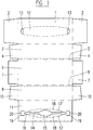
- FIG. 1 shows a plan view of a blank for a box according to a first embodiment of the invention, which is particularly suitable for the repeated removal of towels or the like.
- the blank 1 - 11 consists of a single, flat piece of cardboard, which is formed by punching or cutting out a larger piece of cardboard, with creasing, perforation or embossing lines (shown in broken lines or dash-dotted lines), which fold lines and / or tear lines are pre-punched for the box to be formed.
- the box is made of cardboard in this example, it can also be molded from a plastic film of suitable rigidity or a similar material.
- the blank comprises an outer upper wall section 1 with end flaps 2, a first side wall section 3 with end flaps 4, a first flap section 5, a bottom wall section 6 with end flaps 7, a second flap section 8, a second side wall section 9 with end flaps 10 and an inner upper wall section 11 .
- the different sections with their end flaps are foldably connected to one another via crease and perforation lines, as shown in FIG. 1.
- the outer upper wall section 1 has a tear-out strip 12 and openings 13 at its ends.
- the inner upper wall section 11 has a slot-shaped opening section 14, 15, 16, which is delimited by lateral, movable flaps 17 at least over part of its length.
- the flaps 17 are connected along perforation lines 18 to the inner upper wall section 11 of the box and, in the closed position, define a slot area which has slot sections 14 of approximately constant width and an enlarged central part 15.
- the slot sections 14 are adjoined on the outside by two cut end sections 16 which narrow outwards.
- the outer upper wall section 1 and the inner upper wall section 11 together form the upper wall of the box (see FIG. 2).
- the sections 1 and 11 are fixed to one another (for example glued) in such a way that the tearable strip 12 covers the opening section 14, 15, 16.
- the inner section 11, which has the flaps 17 delimiting the opening section 14, 15, 16, is provided on both sides (corresponding to the end openings 13) with a tongue 20 cut free by a cutting line 19 to facilitate the tearing out of the strip 12.
- a tongue 20 can deflect inwards when reaching under the strip 12.
- the intermediate product is held, pressure being exerted on the upper wall 1, 11 and on the side walls 3, 9, so that the tab sections 5 and 8 on the bottom wall section 6 are folded in and thereby folded together with it, after which it is known per se
- the end flaps 4 and 10 are folded inwards and the end flaps 2 and 7 are folded onto one another and fixed (for example glued).
- the two above reinforcing and guide flaps 21 are formed and fixed in their position without additional gluing.
- the tab sections 5 and 8 are first folded and glued to the bottom wall section 6. Then the side wall sections 3 and 9 and the end flaps 4, 10 and 7 are erected and glued in a manner known per se. After the product has been filled in, the package is then closed by folding and gluing the outer and inner upper wall sections 1 and 11 and the end flaps 2.
- FIG. 2 shows a perspective view of the box according to the first embodiment of the invention after the strip 12 has been torn out.
- the outer upper wall section 1 forms, together with the inner upper wall section 11, the upper wall of the box.
- the strip 12 (see FIG. 1) has already been torn out, so that the opening section 14, 15, 16 is exposed and part of the inner upper wall section 11 is also visible. That through the cutting line 19 cut tongue 20 is not shown in Figure 2.
- the tab section 5 is folded together with the bottom wall section 6 and forms the projecting tab 21. In exactly the same way, the other tab section 8 with the bottom wall section 6 on the other side also forms a projecting tab 21.
- the box can be made by simply folding and fixing it from the one-piece, pre-cut blank 1 - 11. At least one of the surfaces of the box (in the example shown the bottom wall section 6) has two parallel edges, each of which has a projecting tab 21. Depending on the molding process, these tabs 21 can be realized without any additional consumption of material or adhesive and while maintaining the inexpensive manufacture of the box.
- the tabs 21 lie essentially in the plane of the surface in question (the bottom wall 6) and run over the entire length of the respective opposite edges. They increase the stability of the box, which means that the packaging is better protected against mechanical deformation, which increases product protection. Above all, however, they can advantageously be used as an aid for fastening the box during its use as a dispenser.
- the box can easily be attached to a wall, in a cupboard, etc. (for example using rails or an inexpensive mounting plate with grooves) and thus serves as a quickly replaceable dispenser without the need for an expensive container. This is explained in more detail below.
- the box is almost cuboid. If the upper wall section 1, 11 and the bottom wall section 6 have the same width (which is technically necessary to obtain a glued in the longitudinal direction and still collapsible intermediate is usually a condition), the box is not rectangular in cross section perpendicular to the longitudinal axis, but slightly trapezoidal. If the box is formed from a non-pre-glued blank directly on the packaging machine, it is possible to achieve an almost perfect cuboid shape for the box through a somewhat wider bottom wall, apart from the tabs 21, of course.
- the slit-shaped opening section 14, 15, 16 is used, for example, for the repeated removal of paper towels, facial tissues, facial tissues or the like from the box.
- the symmetrical, side flaps 17 are movably connected to the inner upper wall section 11 by the perforation lines 18 and define relatively narrow slot parts 14 at both ends between practically parallel inner edges of the flaps 17, and an enlarged, oval middle part 15.
- the movable flaps or lips 17 allow, on the one hand, thanks to the metered braking action, the problem-free removal of wipes without the risk of them tearing, or that more than one wipe escapes at the same time, or that the next wipe remains so far that it is no longer easy to grasp and can be removed.
- the removal opening can be made relatively small, so that the contents of the box are well protected against dust and other influences.
- several independent flaps with different dimensions and / or different mobility are also possible on both sides.
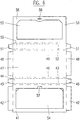
- FIG. 3 shows a plan view of a blank for a box according to a second embodiment of the invention, which is particularly suitable for receiving a roll with a wound film material and for separating and releasing pieces of this material from the roll received in the box.
- the blank 22 - 33 in turn consists of a single, flat piece of cardboard, which is formed by punching or cutting out a larger piece of cardboard, with perforation and crease lines (shown in broken lines or dash-dotted lines) being pre-punched, which fold lines and / or tear lines for the Form the box to be formed.
- the blank comprises an outer upper wall section 22 with end flaps 23 and a side adhesive flap 24, a first side wall section 25 with end flaps 26, a first flap section 27, a bottom wall section 28 with end flaps 29, a second flap section 30, a second side wall section 31 with end flaps 32 and an inner upper wall section 33.
- the different sections with their end flaps are foldably connected to one another via crease and perforation lines, as shown in FIG. 3.
- the outer upper wall section 22 has a tear-out strip 34 and openings 35 on its front edges.
- the inner upper wall section 33 has a slit-shaped opening section 36, which corresponds approximately to the tear-out strip 34.
- the end flaps 26 and 32 of the side wall sections 25 and 31 are provided with additional embossing lines for forming centering cams, as explained in more detail below becomes.
- the outer upper wall section 22 is further provided with a separating edge which is suitable for separating pieces of a rolled-up material from a roll inserted into the box.
- the separating edge is formed by a sawtooth-shaped cutting line 37 which is interrupted by a number of creasing bars for reasons of stability. The cutting edge is thus formed from the cutting material and is thus completely integrated into the packaging.
- the blank is folded and fixed in a manner similar to that described above in connection with FIGS. 1 and 2.
- the outer and inner upper wall sections 22 and 33 are glued together again.
- the side adhesive tab 24 serves to reinforce the connection.
- the exterior is glued to the inside of the relevant side wall section at a distance from the edge corresponding to its width.
- an elongated discharge opening for the wound material is formed in the upper wall 22, 33.
- This discharge opening is provided in parallel and at a distance from the separating edge. This ensures simple, clean and complete separation, even from narrow strips of film material.
- FIG. 4 shows a schematic top view, partly in section
- FIG. 5 shows a top view Perspective view of the box according to the second embodiment of the invention after strip 34 has been torn out.
- the outer upper wall section 22 together with the inner upper wall section 33 forms the upper wall of the box with the elongated delivery opening.
- the strip 34 (see FIG. 3) has already been torn out, so that a user has access to the rolled-up material of the roll 40 through the discharge opening 36.
- the sawtooth-shaped cutting line 37 forms the separating edge projecting slightly beyond the side wall 25.
- the tab section 27 is folded together with the bottom wall section 28 and forms the projecting tab 39.
- the other tab section 30 with the bottom wall section 28 on the other side also forms a projecting tab 39.
- the centering cams 38 not only center the roller 40, but also reduce it also the friction occurring on the end faces of the packaging when the roller 40 is rotated.
- the box can in turn be made by simply folding and fixing it from the one-piece, pre-punched blank 22 - 33.
- At least one of the surfaces of the box in the example shown the bottom wall section 28
- These tabs 39 lie essentially in the plane of the surface in question (the bottom wall 28) and, depending on the molding process, can be realized without any additional consumption of production material and adhesive and while maintaining the inexpensive production of the box. They increase the stability of the box and can advantageously be used as an aid for fastening the box while it is being used as a dispenser.
- the embodiment described with reference to Figures 3 to 5 is as a dispensing device, for example in the kitchen usable for household paper, aluminum foil, cling film, baking paper, freezer bags or the like.
- FIG. 6 shows a plan view of a blank for a box according to a third embodiment of the invention, which is suitable, for example, as a stable and decorative box of chocolates.
- the blank 41 - 53 in turn consists of a single, flat piece of cardboard, which is formed by punching or cutting out a larger piece of cardboard, perforation or crease lines (shown in broken lines or dash-dotted lines) being pre-punched, which fold lines and / or tear lines for the Form the box to be formed.
- the blank comprises an outer top wall section 41 with end straps 42, a first strap section 43, a first side wall section 44 with end straps 45, a second strap section 46, a bottom wall section 47 with end straps 48, a third strap section 49, a second side wall section 50 with end straps 51, a fourth tab section 52 and an inner upper wall section 53.
- the various sections with their end tabs are foldably connected to one another via crease and perforation lines, as shown in FIG. 6.
- the outer upper wall section 41 has a movable cover part 54.
- the inner upper wall section 53 has a support edge 56 for the cover part 54 which delimits an opening 55.
- the cover part 54 is provided with a sealing lip 57 and the support edge 56 with a corresponding sealing slot 58.
- the blank is again folded and fixed in a manner similar to that described above in connection with FIGS. 1 and 2.
- the outer and inner upper wall sections 41 and 53 are glued together again. Now, however, not only two but four projecting tabs 59 (see FIGS. 7 and 8 in particular) are formed.
- the tab portions 46 and 49 are folded together with the bottom wall portion 47, the tab portion 43 is folded with the outer upper wall portion 41, and the tab portion 52 is folded with the inner upper wall portion 53 to form the protruding tabs 59.
- FIG. 7 shows a schematic plan view of a box according to the third embodiment of the invention with the lid 54 closed
- FIG. 8 shows a perspective view of the box according to the third embodiment of the invention with the lid 54 open.
- the outer upper wall section 41 forms, together with the inner upper wall section 53, the upper wall of the box with the lid 54. With the lid 54 open, the user has access to the contents of the box through the discharge opening 55.
- the box is essentially cuboid and in turn can be formed by simply folding and fixing it from the one-piece, pre-punched blank 41-53.
- Two opposite surfaces 41, 47 are each provided with a tab 59 lying in the plane of the respective surface 41, 47 on two parallel edges.
- these tabs 59 can be realized without any additional consumption of material and adhesive and while maintaining the inexpensive manufacture of the box. They significantly increase the stability of the box and also have a decorative effect.
- the embodiment described with reference to FIGS. 6 to 8 can advantageously be used as a decorative box, for example for chocolates.
- the supporting edge 56 for the lid part 54, together with the sealing lip 57 and the corresponding sealing slot 58, ensures the reliable closing of the box, even after it has been opened repeatedly.
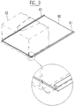
- FIG. 9 shows a perspective view of a fastening device for a box according to the invention.
- the boxes of the first and second embodiments can be attached very advantageously to such a fastening device with the aid of the tabs.
- the fastening device comprises a plate 60 with two parallel guide or holding grooves 61 with a U-shaped cross section for receiving the tabs of the box 62 shown in dashed lines.
- the part shown on an enlarged scale illustrates the guide of the tab in the groove 61.
- the flaps of the box allow them to be easily and quickly attached to the plate 60.
- No expensive housing is required.
- the plate 60 can, in a manner known per se, be fastened in a cupboard, on a wall or on another piece of furniture by means of screws or adhesive, not shown.
- the plate 60 can be made of stainless sheet, anodized aluminum, plastic, wood, etc.
- the dimensions of the plate 60 of course correspond to those of the box 62 to be used.
- a plurality of pairs of grooves 61 can also be provided on a plate for different packaging formats and filling goods. When the box 62 is not in use, there is no protruding, space-wasting housing. An empty package 62 can be replaced very quickly and easily.
- the fastening device comprises at least two parallel rail pieces for receiving the tabs of the box. This results in an even more economical and space-saving fastening device.
- the rail pieces or holding grooves can already be integrated in the manufacture of mirror cabinets, kitchen furniture, bathroom furniture and the like.
- FIG. 10 shows a perspective view of a further fastening device for a box according to the invention.
- This embodiment is even less expensive and moreover less visually striking. It comprises four short, parallel rail sections 63 for receiving the respective tab ends of the box to be fastened.
- the rail sections 63 are advantageously fastened to an auxiliary cardboard 64 which corresponds to the dimensions of the surface of the box to be fastened and which serves as a distance gauge.
- the rail sections 63 can be positioned very precisely on the wall, corresponding to the package width.
- the box can then be inserted. A simple assembly aid is thus implemented.
- the distance gauge 64 can of course also be used in combination with the parallel rail pieces described earlier. It is also possible to use only two rail sections 63.
- the box according to the invention can advantageously be used in the kitchen, bathroom, etc.
- Dispensing device are used, but also for example in hospitals or laboratories, for dispensing (for example) rubber gloves, hair nets, mouth guards or shoe covers, or in industry, for example for earplugs and the like. Since no housing is required, the packaging design is effective during the entire period of use and can be adapted to the environment and / or provided with relevant information. An empty box can be replaced very easily.
- the packaging and the fasteners are very inexpensive.
Landscapes
- Engineering & Computer Science (AREA)
- Mechanical Engineering (AREA)
- Cartons (AREA)
Priority Applications (2)
| Application Number | Priority Date | Filing Date | Title |
|---|---|---|---|
| DE59603067T DE59603067D1 (de) | 1996-04-25 | 1996-04-25 | Satz, bestehend aus einer Schachtel und einer Befestigungsvorrichtung für die Schachtel |
| EP19960810264 EP0803448B1 (fr) | 1996-04-25 | 1996-04-25 | Kit composé d'une boíte et d'un dispositif de fixation pour la boíte |
Applications Claiming Priority (1)
| Application Number | Priority Date | Filing Date | Title |
|---|---|---|---|
| EP19960810264 EP0803448B1 (fr) | 1996-04-25 | 1996-04-25 | Kit composé d'une boíte et d'un dispositif de fixation pour la boíte |
Publications (2)
| Publication Number | Publication Date |
|---|---|
| EP0803448A1 true EP0803448A1 (fr) | 1997-10-29 |
| EP0803448B1 EP0803448B1 (fr) | 1999-09-15 |
Family
ID=8225595
Family Applications (1)
| Application Number | Title | Priority Date | Filing Date |
|---|---|---|---|
| EP19960810264 Expired - Lifetime EP0803448B1 (fr) | 1996-04-25 | 1996-04-25 | Kit composé d'une boíte et d'un dispositif de fixation pour la boíte |
Country Status (2)
| Country | Link |
|---|---|
| EP (1) | EP0803448B1 (fr) |
| DE (1) | DE59603067D1 (fr) |
Cited By (2)
| Publication number | Priority date | Publication date | Assignee | Title |
|---|---|---|---|---|
| WO2003013983A1 (fr) * | 2001-08-08 | 2003-02-20 | Top & Twel B.V. | Distributeur et procede pour la distribution mesuree d'un materiau en feuille, et ebauche de production d'un tel distributeur |
| US7487906B2 (en) | 2006-05-05 | 2009-02-10 | Conopco, Inc. | Personal care article dispensing carton |
Citations (13)
| Publication number | Priority date | Publication date | Assignee | Title |
|---|---|---|---|---|
| GB423276A (en) * | 1934-01-24 | 1935-01-29 | Jeyes Sanitary Compounds Compa | Improvements in or relating to cartons for interleaved paper, cloth and the like |
| US2096107A (en) * | 1934-02-05 | 1937-10-19 | Harry S Haggerty | Container |
| US2323968A (en) * | 1942-12-05 | 1943-07-13 | Fibre Cord Company | Strip dispensing carton |
| US2324028A (en) * | 1939-12-14 | 1943-07-13 | Fibre Cord Company | Strip dispensing carton |
| FR1315415A (fr) * | 1961-11-21 | 1963-01-18 | Cartiera Di Cairate S P A | Boîtier-réservoir avec pattes de fixation auto-adhésives pour éléments en feuille, tels que papiers détergents ou autres |
| US3333686A (en) * | 1965-10-22 | 1967-08-01 | Fred C Schnabel | Combination dual container and suspension means therefor |
| FR1601230A (fr) * | 1968-12-26 | 1970-08-10 | ||
| GB1229984A (fr) * | 1968-03-26 | 1971-04-28 | ||
| DE8705198U1 (de) * | 1987-01-08 | 1987-07-16 | Lugauer, Ernst, 8000 München | Verpackung |
| US4735317A (en) * | 1986-10-15 | 1988-04-05 | Nordic Industries, Inc. | Self sealing dispenser pack for pre-moistened towelettes |
| DE8906585U1 (de) * | 1989-05-30 | 1989-07-13 | Delkeskamp KG, 4577 Nortrup | Handabroller für folienartiges Material |
| US5141108A (en) * | 1990-10-31 | 1992-08-25 | Waldorf Corporation | Core retaining carton |
| US5219421A (en) * | 1992-06-16 | 1993-06-15 | Reid Dominion Packaging Limited | Paperboard tissue box with paperboard dispenser |
-
1996
- 1996-04-25 DE DE59603067T patent/DE59603067D1/de not_active Expired - Fee Related
- 1996-04-25 EP EP19960810264 patent/EP0803448B1/fr not_active Expired - Lifetime
Patent Citations (13)
| Publication number | Priority date | Publication date | Assignee | Title |
|---|---|---|---|---|
| GB423276A (en) * | 1934-01-24 | 1935-01-29 | Jeyes Sanitary Compounds Compa | Improvements in or relating to cartons for interleaved paper, cloth and the like |
| US2096107A (en) * | 1934-02-05 | 1937-10-19 | Harry S Haggerty | Container |
| US2324028A (en) * | 1939-12-14 | 1943-07-13 | Fibre Cord Company | Strip dispensing carton |
| US2323968A (en) * | 1942-12-05 | 1943-07-13 | Fibre Cord Company | Strip dispensing carton |
| FR1315415A (fr) * | 1961-11-21 | 1963-01-18 | Cartiera Di Cairate S P A | Boîtier-réservoir avec pattes de fixation auto-adhésives pour éléments en feuille, tels que papiers détergents ou autres |
| US3333686A (en) * | 1965-10-22 | 1967-08-01 | Fred C Schnabel | Combination dual container and suspension means therefor |
| GB1229984A (fr) * | 1968-03-26 | 1971-04-28 | ||
| FR1601230A (fr) * | 1968-12-26 | 1970-08-10 | ||
| US4735317A (en) * | 1986-10-15 | 1988-04-05 | Nordic Industries, Inc. | Self sealing dispenser pack for pre-moistened towelettes |
| DE8705198U1 (de) * | 1987-01-08 | 1987-07-16 | Lugauer, Ernst, 8000 München | Verpackung |
| DE8906585U1 (de) * | 1989-05-30 | 1989-07-13 | Delkeskamp KG, 4577 Nortrup | Handabroller für folienartiges Material |
| US5141108A (en) * | 1990-10-31 | 1992-08-25 | Waldorf Corporation | Core retaining carton |
| US5219421A (en) * | 1992-06-16 | 1993-06-15 | Reid Dominion Packaging Limited | Paperboard tissue box with paperboard dispenser |
Cited By (2)
| Publication number | Priority date | Publication date | Assignee | Title |
|---|---|---|---|---|
| WO2003013983A1 (fr) * | 2001-08-08 | 2003-02-20 | Top & Twel B.V. | Distributeur et procede pour la distribution mesuree d'un materiau en feuille, et ebauche de production d'un tel distributeur |
| US7487906B2 (en) | 2006-05-05 | 2009-02-10 | Conopco, Inc. | Personal care article dispensing carton |
Also Published As
| Publication number | Publication date |
|---|---|
| DE59603067D1 (de) | 1999-10-21 |
| EP0803448B1 (fr) | 1999-09-15 |
Similar Documents
| Publication | Publication Date | Title |
|---|---|---|
| DE60121029T2 (de) | Wischtücherspendesystem | |
| AT399701B (de) | Faltschachtelverschluss | |
| DE69016518T2 (de) | Leicht zu öffnender, flexibler Beutel. | |
| EP0726205B1 (fr) | Flans pour une boíte de présentation et transport | |
| DE2900940A1 (de) | Schiebedeckel-karton und zuschnitt dafuer | |
| DE60205929T2 (de) | Behälter für einen stapel von ineinandergefalteten papiertüchern | |
| DE3879056T2 (de) | Flexible ausgabeverpackung fuer impraegnierte servietten. | |
| DE68904734T2 (de) | Quaderfoermige schachtel zur aufnahme von rollen von abreissbarem folienmaterial. | |
| DE69217485T2 (de) | Verpackungsschachtel mit einer Abreissrandschutzvorrichtung | |
| DE29618895U1 (de) | Faltschachtel, insbesondere zur Aufbewahrung von Hygieneartikeln | |
| EP0459110A2 (fr) | Boîte pliable en carton | |
| DE69211219T2 (de) | Öffnungskonstruktion für keilförmige Torteschachtel | |
| EP0803448B1 (fr) | Kit composé d'une boíte et d'un dispositif de fixation pour la boíte | |
| EP0905032A1 (fr) | Flan et récipient construit à partir de ce flan ainsi qu'appareil pour sa fabrication | |
| EP0444444A1 (fr) | Boîte pliante, spécialement pour l'emballage de produits hygiéniques | |
| DE3840963A1 (de) | Zusammenklappbarer behaelter | |
| DE60004774T2 (de) | Schachtel mit zwei zu einander versetzten Ausgabeöffnungen | |
| DE9401359U1 (de) | Getränkekarton | |
| EP4029799A1 (fr) | Boîte pliante pourvue de fermeture inviolable | |
| DE9107954U1 (de) | Verpackungsbeutel aus flexibler Kunststoffolie in Quaderform | |
| DE29513265U1 (de) | Teilbare Verpackung aus Wellpappe oder Karton | |
| DE29715546U1 (de) | Displayverpackungsbehälter | |
| AT404350B (de) | Rolle aus zusammenhängenden abschnitten und spender für derartige rollen | |
| DE3943064A1 (de) | Blisterverpackung | |
| DE4222531A1 (de) | Kartonzuschnitt zur bildung einer faltschachtel fuer schuettgueter |
Legal Events
| Date | Code | Title | Description |
|---|---|---|---|
| PUAI | Public reference made under article 153(3) epc to a published international application that has entered the european phase |
Free format text: ORIGINAL CODE: 0009012 |
|
| AK | Designated contracting states |
Kind code of ref document: A1 Designated state(s): CH DE FR LI |
|
| 17P | Request for examination filed |
Effective date: 19980312 |
|
| 17Q | First examination report despatched |
Effective date: 19980706 |
|
| GRAG | Despatch of communication of intention to grant |
Free format text: ORIGINAL CODE: EPIDOS AGRA |
|
| GRAG | Despatch of communication of intention to grant |
Free format text: ORIGINAL CODE: EPIDOS AGRA |
|
| GRAH | Despatch of communication of intention to grant a patent |
Free format text: ORIGINAL CODE: EPIDOS IGRA |
|
| GRAH | Despatch of communication of intention to grant a patent |
Free format text: ORIGINAL CODE: EPIDOS IGRA |
|
| GRAA | (expected) grant |
Free format text: ORIGINAL CODE: 0009210 |
|
| AK | Designated contracting states |
Kind code of ref document: B1 Designated state(s): CH DE FR LI |
|
| REG | Reference to a national code |
Ref country code: CH Ref legal event code: NV Representative=s name: AMMANN PATENTANWAELTE AG BERN Ref country code: CH Ref legal event code: EP |
|
| REF | Corresponds to: |
Ref document number: 59603067 Country of ref document: DE Date of ref document: 19991021 |
|
| ET | Fr: translation filed | ||
| PLBE | No opposition filed within time limit |
Free format text: ORIGINAL CODE: 0009261 |
|
| STAA | Information on the status of an ep patent application or granted ep patent |
Free format text: STATUS: NO OPPOSITION FILED WITHIN TIME LIMIT |
|
| 26N | No opposition filed | ||
| PGFP | Annual fee paid to national office [announced via postgrant information from national office to epo] |
Ref country code: FR Payment date: 20010420 Year of fee payment: 6 |
|
| PGFP | Annual fee paid to national office [announced via postgrant information from national office to epo] |
Ref country code: DE Payment date: 20010430 Year of fee payment: 6 Ref country code: CH Payment date: 20010430 Year of fee payment: 6 |
|
| PG25 | Lapsed in a contracting state [announced via postgrant information from national office to epo] |
Ref country code: LI Free format text: LAPSE BECAUSE OF NON-PAYMENT OF DUE FEES Effective date: 20020430 Ref country code: CH Free format text: LAPSE BECAUSE OF NON-PAYMENT OF DUE FEES Effective date: 20020430 |
|
| PG25 | Lapsed in a contracting state [announced via postgrant information from national office to epo] |
Ref country code: DE Free format text: LAPSE BECAUSE OF NON-PAYMENT OF DUE FEES Effective date: 20021101 |
|
| REG | Reference to a national code |
Ref country code: CH Ref legal event code: PL |
|
| PG25 | Lapsed in a contracting state [announced via postgrant information from national office to epo] |
Ref country code: FR Free format text: LAPSE BECAUSE OF NON-PAYMENT OF DUE FEES Effective date: 20021231 |
|
| REG | Reference to a national code |
Ref country code: FR Ref legal event code: ST |