EP0803330B1 - Machoire profilée de serrage - Google Patents
Machoire profilée de serrage Download PDFInfo
- Publication number
- EP0803330B1 EP0803330B1 EP97103224A EP97103224A EP0803330B1 EP 0803330 B1 EP0803330 B1 EP 0803330B1 EP 97103224 A EP97103224 A EP 97103224A EP 97103224 A EP97103224 A EP 97103224A EP 0803330 B1 EP0803330 B1 EP 0803330B1
- Authority
- EP
- European Patent Office
- Prior art keywords
- clamping
- clamping jaw
- pressure plate
- main body
- profiled
- Prior art date
- Legal status (The legal status is an assumption and is not a legal conclusion. Google has not performed a legal analysis and makes no representation as to the accuracy of the status listed.)
- Expired - Lifetime
Links
- 238000007789 sealing Methods 0.000 claims description 14
- 239000012530 fluid Substances 0.000 claims description 9
- 230000002093 peripheral effect Effects 0.000 claims 2
- 239000012528 membrane Substances 0.000 abstract description 17
- 239000000565 sealant Substances 0.000 abstract 1
- 230000001681 protective effect Effects 0.000 description 8
- 101100328887 Caenorhabditis elegans col-34 gene Proteins 0.000 description 4
- 239000010720 hydraulic oil Substances 0.000 description 3
- 238000003754 machining Methods 0.000 description 3
- 238000007639 printing Methods 0.000 description 3
- 238000011161 development Methods 0.000 description 2
- 210000003746 feather Anatomy 0.000 description 2
- 230000001788 irregular Effects 0.000 description 2
- 238000012423 maintenance Methods 0.000 description 2
- 239000003921 oil Substances 0.000 description 2
- RRLHMJHRFMHVNM-BQVXCWBNSA-N [(2s,3r,6r)-6-[5-[5-hydroxy-3-(4-hydroxyphenyl)-4-oxochromen-7-yl]oxypentoxy]-2-methyl-3,6-dihydro-2h-pyran-3-yl] acetate Chemical compound C1=C[C@@H](OC(C)=O)[C@H](C)O[C@H]1OCCCCCOC1=CC(O)=C2C(=O)C(C=3C=CC(O)=CC=3)=COC2=C1 RRLHMJHRFMHVNM-BQVXCWBNSA-N 0.000 description 1
- 238000010276 construction Methods 0.000 description 1
- 238000013461 design Methods 0.000 description 1
- 239000011888 foil Substances 0.000 description 1
- 239000000463 material Substances 0.000 description 1
- 238000000034 method Methods 0.000 description 1
- 238000003825 pressing Methods 0.000 description 1
- 238000012549 training Methods 0.000 description 1
- 238000012546 transfer Methods 0.000 description 1
Images

Classifications
-
- B—PERFORMING OPERATIONS; TRANSPORTING
- B25—HAND TOOLS; PORTABLE POWER-DRIVEN TOOLS; MANIPULATORS
- B25B—TOOLS OR BENCH DEVICES NOT OTHERWISE PROVIDED FOR, FOR FASTENING, CONNECTING, DISENGAGING OR HOLDING
- B25B1/00—Vices
- B25B1/24—Details, e.g. jaws of special shape, slideways
- B25B1/2405—Construction of the jaws
- B25B1/241—Construction of the jaws characterised by surface features or material
- B25B1/2415—Construction of the jaws characterised by surface features or material being composed of a plurality of parts adapting to the shape of the workpiece
- B25B1/2421—Construction of the jaws characterised by surface features or material being composed of a plurality of parts adapting to the shape of the workpiece the parts having a linear movement
Definitions
- the invention relates to a mold jaw after Preamble of claim 1.
- Clamping jaws are part of clamping devices such as these for example in vices, machine tools or Machining centers needed to hold workpieces become.
- An example application is the clamping of Turbine blades used to machine the end sections in the middle must be clamped. Because turbine blades are one have irregular shape and multiple blade shapes and - sizes should be machinable in a clamping device, the jaws of the bucket shape must automatically to adjust. Furthermore, it must be ensured that the turbine blade even with high machining forces acting on them be kept safe.
- each shut-off valve is assigned a shut-off valve, through which the fluid connection to the Tappet moving forward hydraulic distributor is lockable.
- the shut-off valves each have one Control piston on, via a second hydraulic distributor pressurized and thereby in its locked position is held.
- each tappet a separate shut-off valve assigning arrangement is, however, the necessary for this complicated structure of the basic body. It is a multitude Shut-off valves to be machined with high precision, which at Damage caused by extensive disassembly of the base body need to be replaced. Furthermore, the control of the Hydraulic oil supply to the individual distribution rooms complicated, because a multi-step, coordinated Order must be adhered to.
- the object of the invention is therefore the construction of a generic Simplify mold clamping jaws and clamping Workpieces with any circumferential contour in a simpler way and reliable way to ensure.
- sealing medium for reliable sealing of the tappet cylinder provided so that saved the O-rings used in the prior art and no matching sealing surfaces can be produced have to.
- the sealing medium is expediently a sealing paste or the like applied to the printing plate.
- the pressure plate is preferably in a base body trained bag arranged so that the membrane without elaborate curve guides on the back of the pressure plate and the base body can be arranged.
- Conveniently is the membrane over a for example Screw fixed lid held on the base body.
- This Design is simplified by the bag, which is a flat Creates contact surface for the lid and the membrane.
- hydraulic lines for the are in the cover Supply of hydraulic fluid to the pressure plate opposite side of the membrane over which the Pressure plate can be pressurized. It is enough here that the hydraulic lines with in the lid trained grooves are connected, the open sides point to the membrane and through which the hydraulic fluid is fed to the membrane. A the membrane completely covering pressure area is not required.
- a Replacing the plunger can be done without removing the Cover, the membrane and the pressure plate are made by the Tension ram on the opposite side from the main body is removed. For this is only the circlip to release and the bushing with the clamping plunger from the plunger cylinder to take out.
- the rams on a film or the like covered This will damage the workpiece surface also avoided at high clamping pressures, since the Protective film that is applied selectively over the tension plunger Pressure distributes and dampens.
- the film is on the side each held in a film holder that swivels is stored and preferably in three degrees of freedom is mobile.
- the film can also do this adapt flexibly to the uneven workpiece surface, see above that damage is avoided.
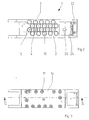
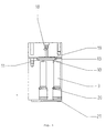
- the mold jaws 1 shown in the drawing exist essentially from a base body 2, in which a variety from 2 open tappet cylinders to one side of the base body 3 is formed.
- each ram cylinder 3 there is one Tension ram 4 (in the drawing is only one example Tappet 4 shown) arranged in the ram cylinder 3 via a piston section 5 and a bushing 6 is slidably supported.
- the socket 6 is from the front in the Ram cylinder 3 is inserted and is via a locking ring 7 held.
- the bushing 6 is opposite the ram cylinder 3 and the plunger 4 sealed via O-rings 8 and 9 respectively.
- Pressure supply opening 10 formed in one in the Base body 2 formed pocket 11 opens into which pressure oil can be introduced via a first hydraulic line 12.
- the pressure plate 13 In the pocket 11 of the base body 2 there is also a pressure plate 13 arranged, the springs 14 on the Base body 2 supports.
- the pressure plate 13 is loose in the Pocket 11 inserted without being guided laterally.
- a membrane 15 is arranged, which over a cover 16, the is fastened to the base body 2 with screws 17 becomes.
- Second hydraulic line 18 connected to the hydraulic pressure source provided that opens into grooves 19 which in the membrane facing side of the cover 16 are formed.
- the Grooves 19 are arranged such that they are essentially the section of the pressure plate 13 Detect membrane 15.
- the function of the mold clamping jaw shown in the drawing 1 is the following:
- the plungers 4 are covered by a protective film 21.
- the Protective film 21 must absorb very large forces and expansions, so that this is an elastic, highly resistant Plastic material is provided. To ensure, that the protective film when extending the ram 4 to the can adjust uneven workpiece surface contour the protective film 21 at its ends via a terminal block 23 in clamped a film holder 22 which is articulated and is movable in three degrees of freedom.
- the film holder 22 is on one in the base body 2 pivoting body pivotally mounted about a first pivot axis A. 24 attached.
- the swivel body 24 is supported against a spring pin 26 biased against a spring 25 Base body 2, so that the protective film 21 is always stretched remains.
- the film holder 22 is also opposite the swivel body 24 via an axially displaceably mounted therein Guide rod 27 axially displaceable.
- the film holder 22 can be pivoted about a second pivot axis B.
- optimal mobility of the protective film 21 is ensured, posed depending on the movement of the Tappet 4 can adjust the workpiece surface contour.
- the film holder 22 can be removed from the swivel body 24 are unhooked, so that the plunger 4 of the Underside of the base body 2 are freely accessible.
- the socket 6 with the Tension plunger 4 simply out of the plunger cylinder 3 can be pulled out and replaced. Dismantling the Cover 16 is therefore not for maintenance of the ram 4 required.
Landscapes
- Engineering & Computer Science (AREA)
- Mechanical Engineering (AREA)
- Jigs For Machine Tools (AREA)
- Mounting, Exchange, And Manufacturing Of Dies (AREA)
- Moulds For Moulding Plastics Or The Like (AREA)
- Thermotherapy And Cooling Therapy Devices (AREA)
- Braking Arrangements (AREA)
Claims (12)
- Mâchoires de serrage adaptables aux formes pour un dispositif de serrage destiné au serrage périphérique de pièces à usiner ayant un contour circonférentiel quelconque, avec un corps de base (2) et avec une surface de serrage disposée sur le corps de base (2) qui est constituée d'une multitude de coulisseaux de serrage (4) pouvant être déplacés indépendamment les uns des autres dans le corps de base (2) et pouvant être bloqués dans leur position de serrage, les coulisseaux de serrage (4) étant guidés chacun dans un cylindre de coulisseau (3) du corps de base (2) et pouvant être déplacés dans le sens du serrage sous l'action d'un fluide hydraulique, les coulisseau de serrage (4) pouvant être bloqués dans leur position de serrage en verrouillant les cylindres de coulisseau (3) à l'aide d'une plaque de pression (13), caractérisées en ce que la plaque de pression (13) s'appuie par le biais de ressorts (14) sur le corps de base (2) et en ce que du côté de la plaque de pression (13) opposé au corps de base (2), il est prévu une membrane (15) à l'aide de laquelle la plaque de pression (13) peut être actionnée par un fluide hydraulique et déplacée contre l'effet des ressorts (14).
- Mâchoires de serrage adaptables aux formes selon la revendication 1, caractérisées en ce que tous les cylindres de coulisseau (3) peuvent être verrouillés au moyen d'une plaque de pression (13) commune.
- Mâchoires de serrage adaptables aux formes selon la revendication 1 ou 2, caractérisées en ce qu'un produit d'étanchéité est prévu du côté de la plaque de pression (13) dirigé vers le corps de base (2) pour rendre étanche de façon fiable les cylindres de coulisseau (3).
- Mâchoires de serrage adaptables aux formes selon la revendication 3, caractérisées en ce que le produit d'étanchéité est une pâte d'étanchéité ou un équivalent.
- Mâchoires de serrage adaptables aux formes selon l'une des revendications 1 à 4, caractérisées en ce que la plaque de pression (13) est placée dans une cavité (11) formée dans le corps de base (2).
- Mâchoires de serrage adaptables aux formes selon l'une des revendications 1 à 5, caractérisées en ce que la membrane (15) est maintenue sur le corps de base (2) par un couvercle (16) fixé par exemple au moyen de vis (17).
- Mâchoires de serrage adaptables aux formes selon la revendication 6, caractérisées en ce que des conduites hydrauliques (18) sont formées dans le couvercle (16) pour alimenter en liquide hydraulique la face de la membrane (15) dirigée vers la plaque de pression (13).
- Mâchoires de serrage adaptables aux formes selon la revendication 7, caractérisées en ce que la conduite hydraulique (18) est en contact avec des gorges (19) formées dans le couvercle (16) et ouvertes en direction de la membrane (15).
- Mâchoires de serrage adaptables aux formes selon l'une des revendications 1 à 8, caractérisées en ce que les coulisseaux de serrage (4) peuvent être introduits dans les cylindres de coulisseau (3) du côté du corps de base (2) opposé à la plaque de pression (13) et peuvent être placés de façon à pouvoir coulisser dans un manchon (6) qui est fixé dans le cylindre de coulisseau (3) par exemple à l'aide d'une rondelle de sécurité (7).
- Mâchoires de serrage adaptables aux formes selon l'une des revendications 1 à 9, caractérisées en ce que les coulisseaux de serrage (4) sont recouverts d'un film (21) ou d'un équivalent.
- Mâchoires de serrage adaptables aux formes selon la revendication 10, caractérisées en ce que le film (21) est maintenu de chaque côté dans un support de film (22) monté de façon à pouvoir pivoter.
- Mâchoires de serrage adaptables aux formes selon la revendication 11, caractérisées en ce que le support de film (22) peut se déplacer selon trois degrés de liberté.
Applications Claiming Priority (2)
| Application Number | Priority Date | Filing Date | Title |
|---|---|---|---|
| DE19615634 | 1996-04-19 | ||
| DE19615634A DE19615634C1 (de) | 1996-04-19 | 1996-04-19 | Formspannbacken |
Publications (2)
| Publication Number | Publication Date |
|---|---|
| EP0803330A1 EP0803330A1 (fr) | 1997-10-29 |
| EP0803330B1 true EP0803330B1 (fr) | 2000-07-19 |
Family
ID=7791847
Family Applications (1)
| Application Number | Title | Priority Date | Filing Date |
|---|---|---|---|
| EP97103224A Expired - Lifetime EP0803330B1 (fr) | 1996-04-19 | 1997-02-27 | Machoire profilée de serrage |
Country Status (3)
| Country | Link |
|---|---|
| EP (1) | EP0803330B1 (fr) |
| AT (1) | ATE194789T1 (fr) |
| DE (2) | DE19615634C1 (fr) |
Families Citing this family (7)
| Publication number | Priority date | Publication date | Assignee | Title |
|---|---|---|---|---|
| DE19752783A1 (de) * | 1997-11-28 | 1999-06-02 | Bayerische Motoren Werke Ag | Vorrichtung zum Spannen eines insbesondere Freiformflächen aufweisenden Werkstücks |
| DE10055591A1 (de) * | 2000-11-09 | 2002-05-23 | Voith Paper Patent Gmbh | Klemmvorrichtung |
| DE10334671B4 (de) * | 2003-07-30 | 2005-10-20 | Theodor Graebener Gmbh & Co Kg | Zylindereinheit zur Anbringung an einer Traverse und/oder einem Tisch einer Vorrichtung oder Maschine zum Umformen von Werkstücken |
| CN108262627B (zh) * | 2017-01-04 | 2023-10-10 | 江苏海盛汽车零部件科技有限公司 | 一种用于夹持铝棒的夹具 |
| CN115647875A (zh) * | 2022-10-09 | 2023-01-31 | 北京航天华世科技股份有限公司 | 钻床用异形零部件加工装置 |
| CN116619089A (zh) * | 2023-07-03 | 2023-08-22 | 昆山佩鑫智能科技有限公司 | 一种用于金属加工的夹制具及其夹制方法 |
| CN119159036A (zh) * | 2024-11-21 | 2024-12-20 | 陕西华威科技股份有限公司 | 一种热锻件夹送装置 |
Family Cites Families (12)
| Publication number | Priority date | Publication date | Assignee | Title |
|---|---|---|---|---|
| DE257815C (fr) * | ||||
| DE423180C (de) * | 1924-11-23 | 1925-12-22 | Anton Thiel | Vorrichtung zum Messen von Beinverkuerzungen |
| US2340316A (en) * | 1941-11-03 | 1944-02-01 | Herman P Fest | Elastic attachment for vise jaws |
| US2399824A (en) * | 1943-08-09 | 1946-05-07 | Irving L Pressman | Adjustable jig and holder |
| DE871280C (de) * | 1945-10-15 | 1953-03-23 | Ernst Flueck | Schraubstock mit gegeneinander kippbaren oder in mehrere Spannfinger aufgeteilten Backen |
| SE393317B (sv) * | 1975-09-25 | 1977-05-09 | Westin & Backlund Ab | Anordning for att stoda och/eller fastspenna kroppar med oregelbunden form |
| FR2535830B1 (fr) * | 1982-11-10 | 1986-06-13 | Trefilunion | Dispositif de positionnement d'elements sur un plateau pour la fabrication de palettes de manutention |
| DE9218907U1 (de) * | 1992-01-25 | 1996-02-15 | Götz GmbH Metall- und Anlagenbau, 97084 Würzburg | Formspannbacken zum Einspannen von Werkstücken |
| DE9204691U1 (de) * | 1992-02-12 | 1992-06-17 | Schrade GmbH, 7143 Vaihingen | Einspannvorrichtung für Gegenstände mit unebener Oberfläche |
| DE4213490C1 (de) * | 1992-04-24 | 1993-09-30 | Deutsche Aerospace Airbus | Zusammengesetzter Formkörper einer Vorrichtung zum Streckziehen eines sphärisch gekrümmten Bleches |
| DE4311110A1 (de) * | 1993-04-05 | 1994-10-06 | Goetz Metall Anlagen | Formspannbacken für eine Spannvorrichtung |
| GB2278825A (en) * | 1993-06-12 | 1994-12-14 | Rolls Royce Plc | Gripper. |
-
1996
- 1996-04-19 DE DE19615634A patent/DE19615634C1/de not_active Expired - Fee Related
-
1997
- 1997-02-27 EP EP97103224A patent/EP0803330B1/fr not_active Expired - Lifetime
- 1997-02-27 DE DE59702043T patent/DE59702043D1/de not_active Expired - Fee Related
- 1997-02-27 AT AT97103224T patent/ATE194789T1/de not_active IP Right Cessation
Also Published As
| Publication number | Publication date |
|---|---|
| ATE194789T1 (de) | 2000-08-15 |
| EP0803330A1 (fr) | 1997-10-29 |
| DE19615634C1 (de) | 1997-09-25 |
| DE59702043D1 (de) | 2000-08-24 |
Similar Documents
| Publication | Publication Date | Title |
|---|---|---|
| DE19950706C2 (de) | Aufspanneinrichtung | |
| DE3723494C2 (de) | Spannvorrichtung | |
| EP0628362B1 (fr) | Outil de pressage | |
| CH654779A5 (de) | Pneumatisch angetriebene spannvorrichtung. | |
| DE1966880C3 (de) | Abschereinrichtung für eine Quertransportpresse | |
| DE2905623A1 (de) | Befestigungsanordnung | |
| EP1118424B1 (fr) | Dispositif de serrage | |
| EP0473954A1 (fr) | Dispositif de serrage pour pièces d'usinage | |
| EP0017660A1 (fr) | Presse hydraulique | |
| EP0803330B1 (fr) | Machoire profilée de serrage | |
| DE2754357C2 (fr) | ||
| DE900044C (de) | Werkzeugmaschine mit selbsttaetiger Einstellung des Schlittens | |
| EP0249059B1 (fr) | Actionnement par air comprimé pour des dispositifs de poinçonnage, coupe et estampage | |
| EP0785049B1 (fr) | Table de support avec dispositif de serrage | |
| DE3329942C1 (de) | Spannvorrichtung für insbes. spanabhebend zu bearbeitende Werkstücke | |
| DE4114295C2 (de) | Dreh-Zug-Spannelement | |
| DE2516454A1 (de) | Druckmittelbetaetigte presse zur spanlosen formgebung | |
| DE4012883C1 (en) | Workpiece fixture - has clamp holding with centrally rotational symmetrical clamping surface and adjustable jaws | |
| DE3304876A1 (de) | Automatische werkstueck-spannvorrichtung fuer eine werkzeugmaschine | |
| DE4011107C2 (fr) | ||
| EP0614728B1 (fr) | Etan | |
| EP0919356B1 (fr) | Machine à former par le vide pour reformer des articles | |
| DE3803397C2 (fr) | ||
| EP0659501B1 (fr) | Machine à forger | |
| DE4042364A1 (de) | Einspannvorrichtung, spannzylinder sowie verfahren zum einspannen eines werkstuecks |
Legal Events
| Date | Code | Title | Description |
|---|---|---|---|
| PUAI | Public reference made under article 153(3) epc to a published international application that has entered the european phase |
Free format text: ORIGINAL CODE: 0009012 |
|
| AK | Designated contracting states |
Kind code of ref document: A1 Designated state(s): AT CH DE FR GB LI SE |
|
| 17P | Request for examination filed |
Effective date: 19980131 |
|
| 17Q | First examination report despatched |
Effective date: 19980930 |
|
| GRAG | Despatch of communication of intention to grant |
Free format text: ORIGINAL CODE: EPIDOS AGRA |
|
| GRAG | Despatch of communication of intention to grant |
Free format text: ORIGINAL CODE: EPIDOS AGRA |
|
| GRAH | Despatch of communication of intention to grant a patent |
Free format text: ORIGINAL CODE: EPIDOS IGRA |
|
| RAP1 | Party data changed (applicant data changed or rights of an application transferred) |
Owner name: SCHAETZLE HOLDING GMBH |
|
| GRAH | Despatch of communication of intention to grant a patent |
Free format text: ORIGINAL CODE: EPIDOS IGRA |
|
| GRAA | (expected) grant |
Free format text: ORIGINAL CODE: 0009210 |
|
| AK | Designated contracting states |
Kind code of ref document: B1 Designated state(s): AT CH DE FR GB LI SE |
|
| PG25 | Lapsed in a contracting state [announced via postgrant information from national office to epo] |
Ref country code: GB Free format text: LAPSE BECAUSE OF FAILURE TO SUBMIT A TRANSLATION OF THE DESCRIPTION OR TO PAY THE FEE WITHIN THE PRESCRIBED TIME-LIMIT Effective date: 20000719 Ref country code: FR Free format text: LAPSE BECAUSE OF FAILURE TO SUBMIT A TRANSLATION OF THE DESCRIPTION OR TO PAY THE FEE WITHIN THE PRESCRIBED TIME-LIMIT Effective date: 20000719 |
|
| REF | Corresponds to: |
Ref document number: 194789 Country of ref document: AT Date of ref document: 20000815 Kind code of ref document: T |
|
| REG | Reference to a national code |
Ref country code: CH Ref legal event code: EP |
|
| RAP2 | Party data changed (patent owner data changed or rights of a patent transferred) |
Owner name: S + B TECHNOLOGIE SCHAETZLE + BERGMANN GMBH & CO. |
|
| REF | Corresponds to: |
Ref document number: 59702043 Country of ref document: DE Date of ref document: 20000824 |
|
| REG | Reference to a national code |
Ref country code: CH Ref legal event code: NV Representative=s name: OK PAT AG |
|
| PG25 | Lapsed in a contracting state [announced via postgrant information from national office to epo] |
Ref country code: SE Free format text: LAPSE BECAUSE OF FAILURE TO SUBMIT A TRANSLATION OF THE DESCRIPTION OR TO PAY THE FEE WITHIN THE PRESCRIBED TIME-LIMIT Effective date: 20001019 |
|
| EN | Fr: translation not filed | ||
| GBV | Gb: ep patent (uk) treated as always having been void in accordance with gb section 77(7)/1977 [no translation filed] |
Effective date: 20000719 |
|
| PLBE | No opposition filed within time limit |
Free format text: ORIGINAL CODE: 0009261 |
|
| STAA | Information on the status of an ep patent application or granted ep patent |
Free format text: STATUS: NO OPPOSITION FILED WITHIN TIME LIMIT |
|
| 26N | No opposition filed | ||
| PGFP | Annual fee paid to national office [announced via postgrant information from national office to epo] |
Ref country code: AT Payment date: 20030220 Year of fee payment: 7 |
|
| PGFP | Annual fee paid to national office [announced via postgrant information from national office to epo] |
Ref country code: CH Payment date: 20030221 Year of fee payment: 7 |
|
| PGFP | Annual fee paid to national office [announced via postgrant information from national office to epo] |
Ref country code: DE Payment date: 20030430 Year of fee payment: 7 |
|
| PG25 | Lapsed in a contracting state [announced via postgrant information from national office to epo] |
Ref country code: AT Free format text: LAPSE BECAUSE OF NON-PAYMENT OF DUE FEES Effective date: 20040227 |
|
| PG25 | Lapsed in a contracting state [announced via postgrant information from national office to epo] |
Ref country code: LI Free format text: LAPSE BECAUSE OF NON-PAYMENT OF DUE FEES Effective date: 20040229 Ref country code: CH Free format text: LAPSE BECAUSE OF NON-PAYMENT OF DUE FEES Effective date: 20040229 |
|
| PG25 | Lapsed in a contracting state [announced via postgrant information from national office to epo] |
Ref country code: DE Free format text: LAPSE BECAUSE OF NON-PAYMENT OF DUE FEES Effective date: 20040901 |
|
| REG | Reference to a national code |
Ref country code: CH Ref legal event code: PL |