EP0803330B1 - Profiled clamping jaw - Google Patents
Profiled clamping jaw Download PDFInfo
- Publication number
- EP0803330B1 EP0803330B1 EP97103224A EP97103224A EP0803330B1 EP 0803330 B1 EP0803330 B1 EP 0803330B1 EP 97103224 A EP97103224 A EP 97103224A EP 97103224 A EP97103224 A EP 97103224A EP 0803330 B1 EP0803330 B1 EP 0803330B1
- Authority
- EP
- European Patent Office
- Prior art keywords
- clamping
- clamping jaw
- pressure plate
- main body
- profiled
- Prior art date
- Legal status (The legal status is an assumption and is not a legal conclusion. Google has not performed a legal analysis and makes no representation as to the accuracy of the status listed.)
- Expired - Lifetime
Links
Images

Classifications
-
- B—PERFORMING OPERATIONS; TRANSPORTING
- B25—HAND TOOLS; PORTABLE POWER-DRIVEN TOOLS; MANIPULATORS
- B25B—TOOLS OR BENCH DEVICES NOT OTHERWISE PROVIDED FOR, FOR FASTENING, CONNECTING, DISENGAGING OR HOLDING
- B25B1/00—Vices
- B25B1/24—Details, e.g. jaws of special shape, slideways
- B25B1/2405—Construction of the jaws
- B25B1/241—Construction of the jaws characterised by surface features or material
- B25B1/2415—Construction of the jaws characterised by surface features or material being composed of a plurality of parts adapting to the shape of the workpiece
- B25B1/2421—Construction of the jaws characterised by surface features or material being composed of a plurality of parts adapting to the shape of the workpiece the parts having a linear movement
Definitions
- the invention relates to a mold jaw after Preamble of claim 1.
- Clamping jaws are part of clamping devices such as these for example in vices, machine tools or Machining centers needed to hold workpieces become.
- An example application is the clamping of Turbine blades used to machine the end sections in the middle must be clamped. Because turbine blades are one have irregular shape and multiple blade shapes and - sizes should be machinable in a clamping device, the jaws of the bucket shape must automatically to adjust. Furthermore, it must be ensured that the turbine blade even with high machining forces acting on them be kept safe.
- each shut-off valve is assigned a shut-off valve, through which the fluid connection to the Tappet moving forward hydraulic distributor is lockable.
- the shut-off valves each have one Control piston on, via a second hydraulic distributor pressurized and thereby in its locked position is held.
- each tappet a separate shut-off valve assigning arrangement is, however, the necessary for this complicated structure of the basic body. It is a multitude Shut-off valves to be machined with high precision, which at Damage caused by extensive disassembly of the base body need to be replaced. Furthermore, the control of the Hydraulic oil supply to the individual distribution rooms complicated, because a multi-step, coordinated Order must be adhered to.
- the object of the invention is therefore the construction of a generic Simplify mold clamping jaws and clamping Workpieces with any circumferential contour in a simpler way and reliable way to ensure.
- sealing medium for reliable sealing of the tappet cylinder provided so that saved the O-rings used in the prior art and no matching sealing surfaces can be produced have to.
- the sealing medium is expediently a sealing paste or the like applied to the printing plate.
- the pressure plate is preferably in a base body trained bag arranged so that the membrane without elaborate curve guides on the back of the pressure plate and the base body can be arranged.
- Conveniently is the membrane over a for example Screw fixed lid held on the base body.
- This Design is simplified by the bag, which is a flat Creates contact surface for the lid and the membrane.
- hydraulic lines for the are in the cover Supply of hydraulic fluid to the pressure plate opposite side of the membrane over which the Pressure plate can be pressurized. It is enough here that the hydraulic lines with in the lid trained grooves are connected, the open sides point to the membrane and through which the hydraulic fluid is fed to the membrane. A the membrane completely covering pressure area is not required.
- a Replacing the plunger can be done without removing the Cover, the membrane and the pressure plate are made by the Tension ram on the opposite side from the main body is removed. For this is only the circlip to release and the bushing with the clamping plunger from the plunger cylinder to take out.
- the rams on a film or the like covered This will damage the workpiece surface also avoided at high clamping pressures, since the Protective film that is applied selectively over the tension plunger Pressure distributes and dampens.
- the film is on the side each held in a film holder that swivels is stored and preferably in three degrees of freedom is mobile.
- the film can also do this adapt flexibly to the uneven workpiece surface, see above that damage is avoided.
- the mold jaws 1 shown in the drawing exist essentially from a base body 2, in which a variety from 2 open tappet cylinders to one side of the base body 3 is formed.
- each ram cylinder 3 there is one Tension ram 4 (in the drawing is only one example Tappet 4 shown) arranged in the ram cylinder 3 via a piston section 5 and a bushing 6 is slidably supported.
- the socket 6 is from the front in the Ram cylinder 3 is inserted and is via a locking ring 7 held.
- the bushing 6 is opposite the ram cylinder 3 and the plunger 4 sealed via O-rings 8 and 9 respectively.
- Pressure supply opening 10 formed in one in the Base body 2 formed pocket 11 opens into which pressure oil can be introduced via a first hydraulic line 12.
- the pressure plate 13 In the pocket 11 of the base body 2 there is also a pressure plate 13 arranged, the springs 14 on the Base body 2 supports.
- the pressure plate 13 is loose in the Pocket 11 inserted without being guided laterally.
- a membrane 15 is arranged, which over a cover 16, the is fastened to the base body 2 with screws 17 becomes.
- Second hydraulic line 18 connected to the hydraulic pressure source provided that opens into grooves 19 which in the membrane facing side of the cover 16 are formed.
- the Grooves 19 are arranged such that they are essentially the section of the pressure plate 13 Detect membrane 15.
- the function of the mold clamping jaw shown in the drawing 1 is the following:
- the plungers 4 are covered by a protective film 21.
- the Protective film 21 must absorb very large forces and expansions, so that this is an elastic, highly resistant Plastic material is provided. To ensure, that the protective film when extending the ram 4 to the can adjust uneven workpiece surface contour the protective film 21 at its ends via a terminal block 23 in clamped a film holder 22 which is articulated and is movable in three degrees of freedom.
- the film holder 22 is on one in the base body 2 pivoting body pivotally mounted about a first pivot axis A. 24 attached.
- the swivel body 24 is supported against a spring pin 26 biased against a spring 25 Base body 2, so that the protective film 21 is always stretched remains.
- the film holder 22 is also opposite the swivel body 24 via an axially displaceably mounted therein Guide rod 27 axially displaceable.
- the film holder 22 can be pivoted about a second pivot axis B.
- optimal mobility of the protective film 21 is ensured, posed depending on the movement of the Tappet 4 can adjust the workpiece surface contour.
- the film holder 22 can be removed from the swivel body 24 are unhooked, so that the plunger 4 of the Underside of the base body 2 are freely accessible.
- the socket 6 with the Tension plunger 4 simply out of the plunger cylinder 3 can be pulled out and replaced. Dismantling the Cover 16 is therefore not for maintenance of the ram 4 required.
Abstract
Description
Die Erfindung betrifft einen Formspannbacken nach dem
Oberbegriff des Anspruchs 1.The invention relates to a mold jaw after
Preamble of
Spannbacken sind Bestandteile von Spannvorrichtungen, wie sie beispielsweise in Schraubstöcken, Werkzeugmaschinen oder Bearbeitungszentren zum Festhalten von Werkstücken benötigt werden. Eine beispielhafte Anwendung ist das Einspannen von Turbinenschaufeln, die zur Bearbeitung der Endabschnitte in der Mitte eingespannt werden müssen. Da Turbinenschaufeln eine unregelmäßige Form aufweisen und mehrere Schaufelformen und -größen in einer Spannvorrichtung bearbeitbar sein sollen, müssen sich die Spannbacken der Schaufelform selbsttätig anpassen. Ferner muß gewährleistet sein, daß die Turbinenschaufel auch bei hohen auf sie wirkenden Bearbeitungskräften sicher gehalten werden. Clamping jaws are part of clamping devices such as these for example in vices, machine tools or Machining centers needed to hold workpieces become. An example application is the clamping of Turbine blades used to machine the end sections in the middle must be clamped. Because turbine blades are one have irregular shape and multiple blade shapes and - sizes should be machinable in a clamping device, the jaws of the bucket shape must automatically to adjust. Furthermore, it must be ensured that the turbine blade even with high machining forces acting on them be kept safe.
Hierzu wird in der DE-A 42 39 180 ein Formspannbacken mit den oben erwähnten Merkmalen vorgeschlagen. Nach Einlegen des Werkstücks zwischen zwei Formspannbacken werden die Spannstößel hydraulisch in den Stößelzylindern vorwärts bewegt, bis ihre die Spannfläche bildenden Druckstücke an der Werkstückoberfläche anliegen. Auf diese Weise kann die Spannfläche sich selbsttätig auch einer unregelmäßig geformten Werkstückoberfläche anpassen. Um die Spannstößel in ihrer Spannstellung zu verriegeln, ist jedem Spannstößel ein Absperrventil zugeordnet, über welches die Fluidverbindung zu einem die Spannstößel vorwärtsbewegenden ersten Hydraulikverteiler absperrbar ist. Die Absperrventile weisen jeweils einen Steuerkolben auf, der über einen zweiten Hydraulikverteiler mit Druck beaufschlagt und hierdurch in seiner Sperrstellung gehalten wird. Soll das Werkstück wieder freigegeben werden, so wird die Druckbeaufschlagung durch den zweiten Hydraulikverteiler gelöst und der Steuerkolben über den auf die gegenüberliegende Seite des Steuerkolbens wirkenden ersten Hydraulikverteiler, in seine Öffnungstellung gedrückt. Wird nun der Druck des ersten Hydraulikverteilers gelöst, so kann die Hydraulikflüssigkeit aus den Stößelzylindern verdrängt werden und die Spannstößel lassen sich aus ihrer Spannstellung in ihre Lösestellung überführen, so daß das Werkstück aus der Spannvorrichtung entnommen werden kann. Nachteilig an einer derartigen, jedem Spannstößel ein gesondertes Absperrventil zuordnenden Anordnung ist jedoch der hierfür erforderliche komplizierte Aufbau des Grundkörpers. Es ist eine Vielzahl hochgenau zu bearbeitender Absperrventile notwendig, die bei einer Beschädigung durch aufwendige Demontage des Grundkörpers ausgetauscht werden müssen. Ferner ist die Steuerung der Hydraulikölzufuhr zu den einzelnen Verteilerräumen kompliziert, da eine vielschrittige, aufeinander abgestimmte Reihenfolge eingehalten werden muß. For this purpose, a mold clamping jaw with the Features mentioned above proposed. After inserting the Work piece between two mold clamping jaws become the clamping plungers hydraulically moved forward in the ram cylinders until their pressure pieces forming the clamping surface on the workpiece surface issue. In this way, the clamping surface itself even an irregularly shaped workpiece surface to adjust. To close the clamping plunger in its clamping position lock, each shut-off valve is assigned a shut-off valve, through which the fluid connection to the Tappet moving forward hydraulic distributor is lockable. The shut-off valves each have one Control piston on, via a second hydraulic distributor pressurized and thereby in its locked position is held. If the workpiece is to be released again, this is how the pressure is applied by the second hydraulic distributor loosened and the control piston over the on the opposite side of the control piston acting first Hydraulic distributor, pressed into its open position. Becomes now the pressure of the first hydraulic distributor is released the hydraulic fluid is displaced from the ram cylinders and the clamping plunger can be removed from their clamping position transfer to their release position so that the workpiece from the Clamping device can be removed. A disadvantage of one Such, each tappet a separate shut-off valve assigning arrangement is, however, the necessary for this complicated structure of the basic body. It is a multitude Shut-off valves to be machined with high precision, which at Damage caused by extensive disassembly of the base body need to be replaced. Furthermore, the control of the Hydraulic oil supply to the individual distribution rooms complicated, because a multi-step, coordinated Order must be adhered to.
Aus der gattungsgemäßen US-A 2 399 824 ist es bekannt, die Stößelzylinder auf einer mit Durchlässen für die Hydraulikflüssigkeit versehenen gemeinsamen Grundplatte zu montieren. Mittels auf einem Laufkörper entsprechend angeordneter Ventilverschlüsse sind die Durchlässe durch Anpressen der Ventilverschlüsse manuell verschließbar, um die Spannstößel in ihrer Spannstellung zu verriegeln. Allerdings sind hierfür die Ventilverschlüsse äußerst genau auf dem Laufkörper zu montieren. Bereits bei geringem Verkanten oder nach Abnutzen der Dichtflächen sind die Durchlässe nicht mehr zuverlässig verschließbar. From the generic US-A 2 399 824 it is known that Ram cylinder on one with hydraulic fluid passages provided common base plate. By means of a correspondingly arranged on a running body Valve closures are the passages by pressing the Valve closures can be closed manually to the clamping plunger lock in their tensioned position. However, are for this the valve closures are extremely close to the barrel assemble. Already with slight tilting or after wear the passages of the sealing surfaces are no longer reliable lockable.
Aufgabe der Erfindung ist es daher, den Aufbau eines gattungsgemäßen Formspannbackens zu vereinfachen und das Spannen von Werkstücken mit beliebiger Umfangskontur auf einfachere Art und Weise zuverlässig zu gewährleisten.The object of the invention is therefore the construction of a generic Simplify mold clamping jaws and clamping Workpieces with any circumferential contour in a simpler way and reliable way to ensure.
Diese Aufgabe wird mit den
Merkmalen des Anspruchs 1 gelöst.This task is accomplished with the
Features of
Auf diese Weise wird nicht nur der Aufbau des Grundkörpers wesentlich vereinfacht, da keine separaten Absperrventile mehr notwendig sind, sondern eine Druckplatte ohne aufwendige Abdichtung über eine Membran mit Druck beaufschlagt werden kann. Vielmehr wird zusätzlich eine wesentliche Vereinfachung der Hydraulikölsteuerung ermöglicht, da die Rückstellung der Druckplatte bei Entlastung des auf sie wirkenden Hydraulikdruckes selbsttätig über die Federn erfolgt und hierzu keine gesonderte Zufuhr von Hydraulikflüssigkeit notwendig ist. Dies vereinfacht und verbilligt somit die Herstellung des Formspannbacken und beschleunigt gleichzeitig bei einfacherer Steuerung den Spann- und Lösevorgang.In this way, not only the structure of the main body considerably simplified since there are no separate shut-off valves are necessary, but a printing plate without expensive Sealing can be pressurized via a membrane can. Rather, it also becomes a significant simplification the hydraulic oil control enables, since the reset of the Pressure plate when the hydraulic pressure acting on it is relieved takes place automatically via the springs and none at all separate supply of hydraulic fluid is necessary. This thus simplifies and reduces the cost of producing the mold clamping jaw and at the same time accelerates with simpler ones Control the tensioning and loosening process.
Gemäß einer bevorzugten Ausgestaltung der Erfindung werden alle Stößelzylinder mittels einer gemeinsamen Druckplatte abgesperrt, so daß in dem Grundkörper keine gesonderten Bohrungen zum Absperren der einzelnen Stößelzylinder ausgebildet werden müssen.According to a preferred embodiment of the invention all ram cylinders using a common pressure plate cordoned off, so that no separate ones in the base body Bores designed to shut off the individual tappet cylinders Need to become.
In Weiterbildung der Erfindung ist auf der dem Grundkörper zugewandten Seite der Druckplatte ein Dichtmedium zum zuverlässigen Abdichten der Stößelzylinder vorgesehen, so daß die im Stand der Technik verwendeten O-Ringe eingespart und keine hierauf abgestimmten Dichtflächen hergestellt werden müssen. Zweckmäßigerweise ist das Dichtmedium eine Dichtpaste oder dergleichen, die auf die Druckplatte aufgetragen wird.In a development of the invention is on the base body facing side of the pressure plate a sealing medium for reliable sealing of the tappet cylinder provided so that saved the O-rings used in the prior art and no matching sealing surfaces can be produced have to. The sealing medium is expediently a sealing paste or the like applied to the printing plate.
Vorzugsweise ist die Druckplatte in einer im Grundkörper ausgebildeten Tasche angeordnet, so daß die Membran ohne aufwendige Kurvenführungen auf der Rückseite der Druckplatte und des Grundkörpers angeordnet werden kann. Zweckmäßigerweise wird hierbei die Membran über einen beispielsweise mit Schrauben fixierten Deckel am Grundkörper gehalten. Diese Gestaltung wird durch die Tasche vereinfacht, die eine ebene Anlagefläche für den Deckel und die Membran schafft.The pressure plate is preferably in a base body trained bag arranged so that the membrane without elaborate curve guides on the back of the pressure plate and the base body can be arranged. Conveniently is the membrane over a for example Screw fixed lid held on the base body. This Design is simplified by the bag, which is a flat Creates contact surface for the lid and the membrane.
In dem Deckel sind erfindungsgemäß Hydraulikleitungen für die Zufuhr von Hydraulikflüssigkeit auf die der Druckplatte abgewandte Seite der Membran ausgebildet, über die die Druckplatte mit Druck beaufschlagt werden kann. Es reicht hierbei aus, daß die Hydraulikleitungen mit in dem Deckel ausgebildeten Nuten in Verbindung stehen, deren offene Seiten zu der Membran weisen und über die die Hydraulikflüssigkeit der Membran zugeführt wird. Ein die Membran vollständig abdeckender Druckbereich ist nicht erforderlich.According to the invention, hydraulic lines for the are in the cover Supply of hydraulic fluid to the pressure plate opposite side of the membrane over which the Pressure plate can be pressurized. It is enough here that the hydraulic lines with in the lid trained grooves are connected, the open sides point to the membrane and through which the hydraulic fluid is fed to the membrane. A the membrane completely covering pressure area is not required.
Gemäß einer bevorzugten Ausführungsform der Erfindung sind die Spannstößel von der der Druckplatte gegenüberliegenden Seite in die Stößelzylinder einsetzbar und in einer Buchse verschiebbar gelagert, welche beispielsweise über einen Sicherungsring in dem Stößelzylinder befestigt ist. Ist ein Spannstößel auszutauschen, so kann dies ohne Entfernen des Deckels, der Membran und der Druckplatte erfolgen, indem der Spannstößel auf der gegenüberliegenden Seite aus dem Grundkörper entnommen wird. Hierzu ist lediglich der Sicherungsring zu lösen und die Buchse mit dem Spannstößel aus dem Stößelzylinder herauszunehmen. According to a preferred embodiment of the invention, the Tappet from the side opposite the pressure plate insertable into the ram cylinder and slidable in a bush stored, which for example via a locking ring is attached in the ram cylinder. Is a Replacing the plunger can be done without removing the Cover, the membrane and the pressure plate are made by the Tension ram on the opposite side from the main body is removed. For this is only the circlip to release and the bushing with the clamping plunger from the plunger cylinder to take out.
Gemäß einer besonders bevorzugten Weiterbildung der Erfindung sind die Spannstößel über eine Folie oder dergleichen abgedeckt. Hierdurch wird einer Beschädigung der Werkstückoberfläche auch bei hohen Spanndrücken vermieden, da die Schutzfolie den punktuell über die Spannstößel aufgebrachten Druck verteilt und dämpft.According to a particularly preferred development of the invention are the rams on a film or the like covered. This will damage the workpiece surface also avoided at high clamping pressures, since the Protective film that is applied selectively over the tension plunger Pressure distributes and dampens.
Um hierbei eine optimale Anpassung der Spannfläche an die Werkstückoberfläche zu ermöglichen, ist die Folie seitlich jeweils in einem Folienhalter gehalten, der schwenkbar gelagert ist und vorzugsweise in drei Freiheitsgraden beweglich ist. Die Folie kann sich auf diese Weise ebenfalls flexibel der ungleichmäßigen Werkstückoberfläche anpassen, so daß eine Beschädigung vermieden wird.In order to optimally adapt the clamping surface to the To enable the workpiece surface, the film is on the side each held in a film holder that swivels is stored and preferably in three degrees of freedom is mobile. The film can also do this adapt flexibly to the uneven workpiece surface, see above that damage is avoided.
Weiterbildungen, Vorteile und Anwendungsmöglichkeiten der Erfindung ergeben sich auch aus der nachfolgenden Beschreibung eines Ausführungsbeispiels und der Zeichnung.Further training, advantages and possible applications of Invention also result from the following description an embodiment and the drawing.
Es zeigen:
- Fig. 1
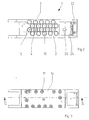
- einen Längsschnitt durch einen erfindungsgemäßen Formspannbacken entlang der Linie I-I in Fig. 3,
- Fig. 2
- eine Ansicht von unten des Formspannbackens gemäß Fig. 1,
- Fig. 3
- eine Draufsicht auf den Formspannbacken gemäß Fig. 1, und
- Fig. 4
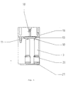
- einen Schnitt entlang der Linie IV-IV in Fig. 1.
- Fig. 1
- 3 shows a longitudinal section through a mold clamping jaw according to the invention along the line II in FIG. 3,
- Fig. 2
- 2 shows a bottom view of the mold clamping jaw according to FIG. 1,
- Fig. 3
- a plan view of the mold jaws according to FIG. 1, and
- Fig. 4
- a section along the line IV-IV in Fig. 1st
Der in der Zeichnung dargestellte Formspannbacken 1 besteht
im wesentlichen aus einem Grundkörper 2, in dem eine Vielzahl
von zu einer Seite des Grundkörpers 2 offenen Stößelzylindern
3 ausgebildet ist. In jedem Stößelzylinder 3 ist ein
Spannstößel 4 (in der Zeichnung ist beispielhaft nur ein
Spannstößel 4 dargestellt) angeordnet, der in dem Stößelzylinder
3 über einen Kolbenabschnitt 5 und eine Buchse 6
gleitend lagert ist. Die Buchse 6 ist von vorne in den
Stößelzylinder 3 eingeführt und wird über einen Sicherungsring
7 gehalten. Die Buchse 6 ist gegenüber dem Stößelzylinder 3
und dem Spannstößel 4 über O-Ringe 8 bzw. 9 abgedichtet.The
An seinem hinteren Ende ist in dem Stößelzylinder 3 eine
Druckzufuhröffnung 10 ausgebildet, die in eine in dem
Grundkörper 2 ausgebildete Tasche 11 mündet, in welche Drucköl
über eine erste Hydraulikleitung 12 einführbar ist.At its rear end is in the
In der Tasche 11 des Grundkörpers 2 ist ferner eine Druckplatte
13 angeordnet, die sich über Federn 14 auf dem
Grundkörper 2 abstützt. Die Druckplatte 13 ist lose in die
Tasche 11 eingesetzt, ohne seitlich geführt zu sein.In the
Auf der dem Grundkörper 2 abgewandten Seite der Druckplatte 13
ist eine Membran 15 angeordnet, die über einen Deckel 16, der
mit Schrauben 17 an dem Grundkörper 2 befestigt ist, gehalten
wird.On the side of the
In dem Deckel 16 ist eine mit einer nicht dargestellten
Hydraulikdruckquelle verbundene zweite Hydraulikleitung 18
vorgesehen, die in Nuten 19 mündet, welche in der der Membran
zugewandten Seite des Deckels 16 ausgebildet sind. Die
Nuten 19 sind hierbei derart angeordnet, daß sie im wesentlichen
den an der Druckplatte 13 anliegenden Abschnitt der
Membran 15 erfassen. In the
In den Stößelzylinder 3 mündet im Bereich zwischen dem
Kolbenabschnitts 5 und der Buchse 6 jeweils eine dritte
Hydraulikleitung 20, über die die Spannstößel 4 in ihre
Ausgangslage zurückführbar sind.In the
Die Funktion des in der Zeichnung dargestellten Formspannbackens
1 ist folgende:The function of the mold clamping jaw shown in the
Nach Einbringen eines nicht dargestellten Werkstücks in eine
die Formspannbacken 1 aufweisende Spannvorrichtung und
Anordnen der Formspannbacken 1 in ihrer Spannstellung wird den
Stößelzylindern 3 über die erste Hydraulikleitung 12, die
Tasche 11 und die Druckzufuhröffnung 10 Drucköl, beispielsweise
unter einem Druck von 6 bis 15 bar, zugeführt, wodurch
die Spannstößel 4 in dem Stößelzylinder 3 verschoben werden,
bis sie an dem Werkstück anliegen. Da jeder Spannstößel 4 auf
diese Weise bis zum Anschlag an der Werkstückoberfläche
ausgefahren wird, kann sich die durch die Spannstößel 4
gebildete Spannfläche exakt der ggf. unregelmäßigen Oberfläche
des Werkstücks, beispielsweise einer Turbinenschaufel,
anpassen. Befinden sich die Spannstößel 4 in ihrer an der
Werkstückoberfläche anliegenden Spannstellung, so wird die
Membran 15 über die zweite Hydraulikleitung 18 und die Nuten
19 im Deckel 16 mit einem hohen Druck, beispielsweise von 60
bar beaufschlagt, wodurch die Druckplatte 13 gegen die Wirkung
der Federn 14 in die Tasche 11 des Grundkörpers 2 hineingedrückt
wird, bis sie am Boden der Tasche 11 anliegt und
die Druckzufuhröffnungen 10 der Stößelzylinder 3 absperrt. Auf
diese Weise werden die Spannstößel 4 zuverlässig in ihrer
Spannstellung verriegelt. Um hierbei eine zuverlässige
Abdichtung der Stößelzylinder 3 zu gewährleisten, ist auf der
Unterseite der Druckplatte 13 ein Dichtmedium, beispielsweise
eine Dichtpaste, vorgesehen. After inserting a workpiece, not shown, into a
the clamping
Ist die Bearbeitung des Werkstücks beendet, so wird zum Lösen
der Spannstößel 4 die Druckzufuhr zu der Membran 15 beendet.
Sobald der auf die Membran 15 wirkende Druck abgebaut ist,
wird die Druckplatte 13 durch die Wirkung der Federn 14
selbsttätig vom Boden der Tasche 11 abgehoben und die
Druckzufuhröffnungen 10 der Stößelzylinder 3 werden geöffnet.
Nun wird über die dritte Hydraulikleitung 20 Hydrauliköl in
die Stößelzylinder 3 eingeführt, das derart auf die Kolbenabschnitte
5 der Spannstößel 4 wirkt, daß diese in die
Stößelzylinder 3 zurückgedrückt werden. Nun befinden sich die
Spannstößel 3 in der in Fig. 1 gezeigten Freigabestellung, so
daß das Werkstück aus der Spannvorrichtung entnommen werden
kann.When the machining of the workpiece is finished, it is released
the
Um eine Beschädigung der Werkstückoberfläche zu vermeiden,
sind die Spannstößel 4 über eine Schutzfolie 21 abgedeckt. Die
Schutzfolie 21 muß sehr große Kräfte und Dehnungen aufnehmen,
so daß hierfür ein elastisches, hochwiderstandsfähiges
Kunststoffmaterial vorgesehen wird. Um sicherzustellen, daß
sich die Schutzfolie beim Ausfahren der Spannstößel 4 an die
ungleichmäßige Werkstückoberflächenkontur anpassen kann, ist
die Schutzfolie 21 an ihren Enden über eine Klemmleiste 23 in
einem Folienhalter 22 eingespannt, der gelenkig gelagert und
in drei Freiheitsgraden beweglich ist.To avoid damaging the workpiece surface,
the
Im einzelnen ist der Folienhalter 22 an einem im Grundkörper
2 um eine erste Schwenkachse A schwenkbar gelagerten Schwenkkörper
24 angebracht. Der Schwenkkörper 24 stützt sich gegen
einen über eine Feder 25 vorgespannten Federstift 26 gegen den
Grundkörper 2 ab, so daß die Schutzfolie 21 immer gespannt
bleibt. Der Folienhalter 22 ist ferner gegenüber dem Schwenkkörper
24 über eine in diesem axial verschiebbar gelagerte
Führungsstange 27 axial verschiebbar. Ferner ist der Folienhalter
22 um eine zweite Schwenkachse B schwenkbar. Hierdurch
wird eine optimale Beweglichkeit der Schutzfolie 21 sichergestellt,
gestellt, die sich in Abhängigkeit von der Bewegung der
Spannstößel 4 der Werkstückoberflächenkontur anpassen kann.In detail, the
Zur Demontage der Spannstößel 4, beispielsweise zur Reparatur
oder Wartung, kann der Folienhalter 22 aus dem Schwenkkörper
24 ausgehakt werden, so daß die Spannstößel 4 von der
Unterseite des Grundkörpers 2 frei zugänglich sind. Nach
Entfernen des Sicherungsringes 7 kann die Buchse 6 mit dem
Spannstößel 4 einfach nach vorne aus dem Stößelzylinder 3
herausgezogen und ausgetauscht werden. Eine Demontage des
Deckels 16 ist zur Wartung der Spannstößel 4 somit nicht
erforderlich.For dismantling the clamping
Mit der Erfindung wird ein Formspannbacken für eine Spannvorrichtung zum Spannen von Werkstücken mit beliebiger Umfangskontur geschaffen, mit dem auf einfache Weise ein zuverlässiges Einspannen des Werkstücks gewährleistet werden kann. With the invention, a mold jaw for a clamping device for clamping workpieces with any circumferential contour created with which in a simple way a reliable Clamping of the workpiece can be guaranteed.
- 11
- FormspannbackenMold jaws
- 22nd
- GrundkörperBasic body
- 33rd
- StößelzylinderRam cylinder
- 44th
- SpannstößelRam
- 55
- KolbenabschnittPiston section
- 66
- BuchseRifle
- 77
- SicherungsringCirclip
- 88th
- O-RingO-ring
- 99
- O-RingO-ring
- 1010th
- DruckzufuhröffnungPressure supply opening
- 1111
- Taschebag
- 1212th
- erste Hydraulikleitungfirst hydraulic line
- 1313
- Druckplatteprinting plate
- 1414
- Federfeather
- 1515
- Membranmembrane
- 1616
- Deckelcover
- 1717th
- SchraubenScrews
- 1818th
- zweite Hydraulikleitungsecond hydraulic line
- 1919th
- NutGroove
- 2020th
- dritte Hydraulikleitungthird hydraulic line
- 2121
- SchutzfolieProtective film
- 2222
- FolienhalterFoil holder
- 2323
- KlemmleisteTerminal block
- 2424th
- SchwenkkörperSwivel body
- 2525th
- Federfeather
- 2626
- FederstiftSpring pin
- 2727
- FührungsstangeGuide rod
- AA
- erste Schwenkachsefirst pivot axis
- BB
- zweite Schwenkachsesecond pivot axis
Claims (12)
- Profiled clamping jaw for a clamping device for peripheral clamping of workpieces with any peripheral contour, with a main body (2) and a clamping surface which is disposed on the main body (2) and is formed by a plurality of clamping rams (4) which are movable independently of one another in the main body (2) and can be locked in their clamping position, wherein the clamping rams (4) are each guided in a ram cylinder (3) of the main body (2) and can be moved in the clamping direction when acted upon by hydraulic fluid, and wherein the clamping rams (4) can be locked in their clamping position by shutting off of the ram cylinders (3) by means of a pressure plate (13), characterised in that the pressure plate (13) is supported by way of springs (14) against the main body (2), and that on the side of the pressure plate (13) remote from the main body (2) a diaphragm (15) is provided by way of which the pressure plate (13) can be acted upon by hydraulic fluid and can be moved against the action of the springs (14).
- Profiled clamping jaw according to Claim 1, characterised in that all ram cylinders (3) can be shut off by means of a common pressure plate (13).
- Profiled clamping jaw according to Claim 1 or 2, characterised in that on the side of the pressure plate (13) facing the main body (2) a sealing medium is provided for reliable sealing of the ram cylinders (3).
- Profiled clamping jaw according to Claim 3, characterised in that the sealing medium is a sealing paste or the like.
- Profiled clamping jaw according to one of Claims 1 to 4, characterised in that the pressure plate (13) is disposed in a pocket (11) constructed in the main body (2).
- Profiled clamping jaw according to one of Claims 1 to 5, characterised in that the diaphragm (15) is held on the main body (2) by way of a cover (16) which is fixed for example by screws (17).
- Profiled clamping jaw according to Claim 6, characterised in that hydraulic ducts (18) for the supply of hydraulic fluid to the side of the diaphragm (15) remote from the pressure plate (13) are constructed in the cover (16).
- Profiled clamping jaw according to Claim 7, characterised in that the hydraulic ducts (18) communicate with grooves (19) which are constructed in the cover (16) and are open towards the diaphragm (15).
- Profiled clamping jaw according to one of Claims 1 to 8, characterised in that the clamping rams (4) can be inserted into the ram cylinders (3) from the side of the main body (2) opposite the pressure plate (13) and are movably mounted in a bush (6) which is fixed in the ram cylinder (3) for example by way of a circlip (7).
- Profiled clamping jaw according to one of Claims 1 to 9, characterised in that the clamping rams (4) are covered by a film (21) or the like.
- Profiled clamping jaw according to Claim 10, characterised in that the film (21) is held laterally in each case in a film holder (22) which is pivotably mounted.
- Profiled clamping jaw according to Claim 11, characterised in that the film holder (22) is movable in three degrees of freedom.
Applications Claiming Priority (2)
| Application Number | Priority Date | Filing Date | Title |
|---|---|---|---|
| DE19615634 | 1996-04-19 | ||
| DE19615634A DE19615634C1 (en) | 1996-04-19 | 1996-04-19 | Mold jaws |
Publications (2)
| Publication Number | Publication Date |
|---|---|
| EP0803330A1 EP0803330A1 (en) | 1997-10-29 |
| EP0803330B1 true EP0803330B1 (en) | 2000-07-19 |
Family
ID=7791847
Family Applications (1)
| Application Number | Title | Priority Date | Filing Date |
|---|---|---|---|
| EP97103224A Expired - Lifetime EP0803330B1 (en) | 1996-04-19 | 1997-02-27 | Profiled clamping jaw |
Country Status (3)
| Country | Link |
|---|---|
| EP (1) | EP0803330B1 (en) |
| AT (1) | ATE194789T1 (en) |
| DE (2) | DE19615634C1 (en) |
Families Citing this family (4)
| Publication number | Priority date | Publication date | Assignee | Title |
|---|---|---|---|---|
| DE19752783A1 (en) * | 1997-11-28 | 1999-06-02 | Bayerische Motoren Werke Ag | Clamping device for work piece with free form surface |
| DE10055591A1 (en) * | 2000-11-09 | 2002-05-23 | Voith Paper Patent Gmbh | Workpiece clamp has two bodies to form the workpiece holder, and a third body pressed against them, to give a firm clamping action with easy release, and which withstands loading forces |
| DE10334671B4 (en) * | 2003-07-30 | 2005-10-20 | Theodor Graebener Gmbh & Co Kg | Cylinder unit for attachment to a crosshead and / or a table of a device or machine for forming workpieces |
| CN108262627B (en) * | 2017-01-04 | 2023-10-10 | 江苏海盛汽车零部件科技有限公司 | Be used for centre gripping Clamp for aluminum bar |
Family Cites Families (12)
| Publication number | Priority date | Publication date | Assignee | Title |
|---|---|---|---|---|
| DE257815C (en) * | ||||
| DE423180C (en) * | 1924-11-23 | 1925-12-22 | Anton Thiel | Device for measuring leg shortening |
| US2340316A (en) * | 1941-11-03 | 1944-02-01 | Herman P Fest | Elastic attachment for vise jaws |
| US2399824A (en) * | 1943-08-09 | 1946-05-07 | Irving L Pressman | Adjustable jig and holder |
| DE871280C (en) * | 1945-10-15 | 1953-03-23 | Ernst Flueck | Vice with jaws that can be tilted towards one another or split into several clamping fingers |
| SE393317B (en) * | 1975-09-25 | 1977-05-09 | Westin & Backlund Ab | DEVICE FOR STANDING AND / OR FIXED BODIES OF IRREGULAR SHAPE |
| FR2535830B1 (en) * | 1982-11-10 | 1986-06-13 | Trefilunion | DEVICE FOR POSITIONING ELEMENTS ON A TRAY FOR THE MANUFACTURE OF HANDLING PALLETS |
| DE9218907U1 (en) * | 1992-01-25 | 1996-02-15 | Goetz Metall Anlagen | Mold clamping jaws for clamping workpieces |
| DE9204691U1 (en) * | 1992-02-12 | 1992-06-17 | Schrade Gmbh, 7143 Vaihingen, De | |
| DE4213490C1 (en) * | 1992-04-24 | 1993-09-30 | Deutsche Aerospace Airbus | Composite shaping body for stretch-forming machine - has supporting heads with similarly-curving surfaces tilting in all directions on jacks for elastic cover accommodating metal sheet |
| DE4311110A1 (en) * | 1993-04-05 | 1994-10-06 | Goetz Metall Anlagen | Mold clamping jaws for a clamping device |
| GB2278825A (en) * | 1993-06-12 | 1994-12-14 | Rolls Royce Plc | Gripper. |
-
1996
- 1996-04-19 DE DE19615634A patent/DE19615634C1/en not_active Expired - Fee Related
-
1997
- 1997-02-27 DE DE59702043T patent/DE59702043D1/en not_active Expired - Fee Related
- 1997-02-27 EP EP97103224A patent/EP0803330B1/en not_active Expired - Lifetime
- 1997-02-27 AT AT97103224T patent/ATE194789T1/en not_active IP Right Cessation
Also Published As
| Publication number | Publication date |
|---|---|
| ATE194789T1 (en) | 2000-08-15 |
| EP0803330A1 (en) | 1997-10-29 |
| DE59702043D1 (en) | 2000-08-24 |
| DE19615634C1 (en) | 1997-09-25 |
Similar Documents
| Publication | Publication Date | Title |
|---|---|---|
| DE19950706C2 (en) | jig | |
| DE3723494C2 (en) | Jig | |
| EP0628362B1 (en) | Press tool | |
| CH654779A5 (en) | PNEUMATICALLY DRIVEN TENSIONER. | |
| DE1966880C3 (en) | Shearing device for a cross transport press | |
| DE2905623A1 (en) | FASTENING ARRANGEMENT | |
| EP1554079B1 (en) | Clamping device for long workpieces in a laser beam machine | |
| EP1118424B1 (en) | Clamping device | |
| EP0473954A1 (en) | Clamping device for workpieces | |
| EP0017660A1 (en) | Hydraulic press | |
| EP0803330B1 (en) | Profiled clamping jaw | |
| DE2754357C2 (en) | ||
| EP0249059B1 (en) | Pneumatic drive for a punching, cutting and stamping device | |
| DE900044C (en) | Machine tool with automatic adjustment of the slide | |
| EP0785049B1 (en) | Support table with clamping device | |
| DE3329942C1 (en) | Clamping device in particular for workpieces to be machined | |
| DE4114295C2 (en) | Rotary-train-tightening element | |
| DE4012883C1 (en) | Workpiece fixture - has clamp holding with centrally rotational symmetrical clamping surface and adjustable jaws | |
| DE3304876A1 (en) | Automatic work-clamping device for a machine tool | |
| DE4011107C2 (en) | ||
| EP0614728B1 (en) | Vice | |
| DE2516454A1 (en) | PRESSURE-ACTUATED PRESS FOR CHIPLESS FORMING | |
| EP0919356B1 (en) | Vacuum forming machine for reshaping articles | |
| DE3803397C2 (en) | ||
| EP0659501B1 (en) | Forging machine |
Legal Events
| Date | Code | Title | Description |
|---|---|---|---|
| PUAI | Public reference made under article 153(3) epc to a published international application that has entered the european phase |
Free format text: ORIGINAL CODE: 0009012 |
|
| AK | Designated contracting states |
Kind code of ref document: A1 Designated state(s): AT CH DE FR GB LI SE |
|
| 17P | Request for examination filed |
Effective date: 19980131 |
|
| 17Q | First examination report despatched |
Effective date: 19980930 |
|
| GRAG | Despatch of communication of intention to grant |
Free format text: ORIGINAL CODE: EPIDOS AGRA |
|
| GRAG | Despatch of communication of intention to grant |
Free format text: ORIGINAL CODE: EPIDOS AGRA |
|
| GRAH | Despatch of communication of intention to grant a patent |
Free format text: ORIGINAL CODE: EPIDOS IGRA |
|
| RAP1 | Party data changed (applicant data changed or rights of an application transferred) |
Owner name: SCHAETZLE HOLDING GMBH |
|
| GRAH | Despatch of communication of intention to grant a patent |
Free format text: ORIGINAL CODE: EPIDOS IGRA |
|
| GRAA | (expected) grant |
Free format text: ORIGINAL CODE: 0009210 |
|
| AK | Designated contracting states |
Kind code of ref document: B1 Designated state(s): AT CH DE FR GB LI SE |
|
| PG25 | Lapsed in a contracting state [announced via postgrant information from national office to epo] |
Ref country code: GB Free format text: LAPSE BECAUSE OF FAILURE TO SUBMIT A TRANSLATION OF THE DESCRIPTION OR TO PAY THE FEE WITHIN THE PRESCRIBED TIME-LIMIT Effective date: 20000719 Ref country code: FR Free format text: LAPSE BECAUSE OF FAILURE TO SUBMIT A TRANSLATION OF THE DESCRIPTION OR TO PAY THE FEE WITHIN THE PRESCRIBED TIME-LIMIT Effective date: 20000719 |
|
| REF | Corresponds to: |
Ref document number: 194789 Country of ref document: AT Date of ref document: 20000815 Kind code of ref document: T |
|
| REG | Reference to a national code |
Ref country code: CH Ref legal event code: EP |
|
| RAP2 | Party data changed (patent owner data changed or rights of a patent transferred) |
Owner name: S + B TECHNOLOGIE SCHAETZLE + BERGMANN GMBH & CO. |
|
| REF | Corresponds to: |
Ref document number: 59702043 Country of ref document: DE Date of ref document: 20000824 |
|
| REG | Reference to a national code |
Ref country code: CH Ref legal event code: NV Representative=s name: OK PAT AG |
|
| PG25 | Lapsed in a contracting state [announced via postgrant information from national office to epo] |
Ref country code: SE Free format text: LAPSE BECAUSE OF FAILURE TO SUBMIT A TRANSLATION OF THE DESCRIPTION OR TO PAY THE FEE WITHIN THE PRESCRIBED TIME-LIMIT Effective date: 20001019 |
|
| EN | Fr: translation not filed | ||
| GBV | Gb: ep patent (uk) treated as always having been void in accordance with gb section 77(7)/1977 [no translation filed] |
Effective date: 20000719 |
|
| PLBE | No opposition filed within time limit |
Free format text: ORIGINAL CODE: 0009261 |
|
| STAA | Information on the status of an ep patent application or granted ep patent |
Free format text: STATUS: NO OPPOSITION FILED WITHIN TIME LIMIT |
|
| 26N | No opposition filed | ||
| PGFP | Annual fee paid to national office [announced via postgrant information from national office to epo] |
Ref country code: AT Payment date: 20030220 Year of fee payment: 7 |
|
| PGFP | Annual fee paid to national office [announced via postgrant information from national office to epo] |
Ref country code: CH Payment date: 20030221 Year of fee payment: 7 |
|
| PGFP | Annual fee paid to national office [announced via postgrant information from national office to epo] |
Ref country code: DE Payment date: 20030430 Year of fee payment: 7 |
|
| PG25 | Lapsed in a contracting state [announced via postgrant information from national office to epo] |
Ref country code: AT Free format text: LAPSE BECAUSE OF NON-PAYMENT OF DUE FEES Effective date: 20040227 |
|
| PG25 | Lapsed in a contracting state [announced via postgrant information from national office to epo] |
Ref country code: LI Free format text: LAPSE BECAUSE OF NON-PAYMENT OF DUE FEES Effective date: 20040229 Ref country code: CH Free format text: LAPSE BECAUSE OF NON-PAYMENT OF DUE FEES Effective date: 20040229 |
|
| PG25 | Lapsed in a contracting state [announced via postgrant information from national office to epo] |
Ref country code: DE Free format text: LAPSE BECAUSE OF NON-PAYMENT OF DUE FEES Effective date: 20040901 |
|
| REG | Reference to a national code |
Ref country code: CH Ref legal event code: PL |