EP0803318A1 - Magasin d'outils et dispositif de changement pour machines à percer travaillant en coordonnées pour plaques à circuit imprimé - Google Patents
Magasin d'outils et dispositif de changement pour machines à percer travaillant en coordonnées pour plaques à circuit imprimé Download PDFInfo
- Publication number
- EP0803318A1 EP0803318A1 EP97103757A EP97103757A EP0803318A1 EP 0803318 A1 EP0803318 A1 EP 0803318A1 EP 97103757 A EP97103757 A EP 97103757A EP 97103757 A EP97103757 A EP 97103757A EP 0803318 A1 EP0803318 A1 EP 0803318A1
- Authority
- EP
- European Patent Office
- Prior art keywords
- magazine
- tool
- drilling
- drilling machine
- machine according
- Prior art date
- Legal status (The legal status is an assumption and is not a legal conclusion. Google has not performed a legal analysis and makes no representation as to the accuracy of the status listed.)
- Withdrawn
Links
- 238000003860 storage Methods 0.000 claims abstract description 35
- 238000005553 drilling Methods 0.000 claims description 96
- 238000003801 milling Methods 0.000 claims description 16
- 239000010438 granite Substances 0.000 claims description 3
- 238000000034 method Methods 0.000 claims description 3
- 238000000151 deposition Methods 0.000 claims 1
- IHQKEDIOMGYHEB-UHFFFAOYSA-M sodium dimethylarsinate Chemical class [Na+].C[As](C)([O-])=O IHQKEDIOMGYHEB-UHFFFAOYSA-M 0.000 claims 1
- 230000008859 change Effects 0.000 description 7
- 238000004519 manufacturing process Methods 0.000 description 4
- 230000007246 mechanism Effects 0.000 description 4
- 238000013461 design Methods 0.000 description 3
- 230000000712 assembly Effects 0.000 description 2
- 238000000429 assembly Methods 0.000 description 2
- 230000008901 benefit Effects 0.000 description 2
- 238000006073 displacement reaction Methods 0.000 description 2
- 238000003754 machining Methods 0.000 description 2
- 230000008569 process Effects 0.000 description 2
- XAGFODPZIPBFFR-UHFFFAOYSA-N aluminium Chemical compound [Al] XAGFODPZIPBFFR-UHFFFAOYSA-N 0.000 description 1
- 229910052782 aluminium Inorganic materials 0.000 description 1
- 238000010276 construction Methods 0.000 description 1
- 238000005516 engineering process Methods 0.000 description 1
- 230000004048 modification Effects 0.000 description 1
- 238000012986 modification Methods 0.000 description 1
- 238000012545 processing Methods 0.000 description 1
- 230000009467 reduction Effects 0.000 description 1
- 238000012546 transfer Methods 0.000 description 1
Images


Classifications
-
- B—PERFORMING OPERATIONS; TRANSPORTING
- B23—MACHINE TOOLS; METAL-WORKING NOT OTHERWISE PROVIDED FOR
- B23Q—DETAILS, COMPONENTS, OR ACCESSORIES FOR MACHINE TOOLS, e.g. ARRANGEMENTS FOR COPYING OR CONTROLLING; MACHINE TOOLS IN GENERAL CHARACTERISED BY THE CONSTRUCTION OF PARTICULAR DETAILS OR COMPONENTS; COMBINATIONS OR ASSOCIATIONS OF METAL-WORKING MACHINES, NOT DIRECTED TO A PARTICULAR RESULT
- B23Q3/00—Devices holding, supporting, or positioning work or tools, of a kind normally removable from the machine
- B23Q3/155—Arrangements for automatic insertion or removal of tools, e.g. combined with manual handling
- B23Q3/1552—Arrangements for automatic insertion or removal of tools, e.g. combined with manual handling parts of devices for automatically inserting or removing tools
- B23Q3/15526—Storage devices; Drive mechanisms therefor
- B23Q3/15539—Plural magazines, e.g. involving tool transfer from one magazine to another
-
- B—PERFORMING OPERATIONS; TRANSPORTING
- B23—MACHINE TOOLS; METAL-WORKING NOT OTHERWISE PROVIDED FOR
- B23Q—DETAILS, COMPONENTS, OR ACCESSORIES FOR MACHINE TOOLS, e.g. ARRANGEMENTS FOR COPYING OR CONTROLLING; MACHINE TOOLS IN GENERAL CHARACTERISED BY THE CONSTRUCTION OF PARTICULAR DETAILS OR COMPONENTS; COMBINATIONS OR ASSOCIATIONS OF METAL-WORKING MACHINES, NOT DIRECTED TO A PARTICULAR RESULT
- B23Q3/00—Devices holding, supporting, or positioning work or tools, of a kind normally removable from the machine
- B23Q3/155—Arrangements for automatic insertion or removal of tools, e.g. combined with manual handling
- B23Q3/157—Arrangements for automatic insertion or removal of tools, e.g. combined with manual handling of rotary tools
- B23Q3/15773—Arrangements for automatic insertion or removal of tools, e.g. combined with manual handling of rotary tools a transfer device taking the tool from a storage device and passing it on to other transfer devices, which insert it in a spindle
-
- B—PERFORMING OPERATIONS; TRANSPORTING
- B23—MACHINE TOOLS; METAL-WORKING NOT OTHERWISE PROVIDED FOR
- B23Q—DETAILS, COMPONENTS, OR ACCESSORIES FOR MACHINE TOOLS, e.g. ARRANGEMENTS FOR COPYING OR CONTROLLING; MACHINE TOOLS IN GENERAL CHARACTERISED BY THE CONSTRUCTION OF PARTICULAR DETAILS OR COMPONENTS; COMBINATIONS OR ASSOCIATIONS OF METAL-WORKING MACHINES, NOT DIRECTED TO A PARTICULAR RESULT
- B23Q3/00—Devices holding, supporting, or positioning work or tools, of a kind normally removable from the machine
- B23Q3/155—Arrangements for automatic insertion or removal of tools, e.g. combined with manual handling
- B23Q3/1552—Arrangements for automatic insertion or removal of tools, e.g. combined with manual handling parts of devices for automatically inserting or removing tools
- B23Q3/15526—Storage devices; Drive mechanisms therefor
- B23Q2003/15537—Linearly moving storage devices
-
- H—ELECTRICITY
- H05—ELECTRIC TECHNIQUES NOT OTHERWISE PROVIDED FOR
- H05K—PRINTED CIRCUITS; CASINGS OR CONSTRUCTIONAL DETAILS OF ELECTRIC APPARATUS; MANUFACTURE OF ASSEMBLAGES OF ELECTRICAL COMPONENTS
- H05K3/00—Apparatus or processes for manufacturing printed circuits
- H05K3/0011—Working of insulating substrates or insulating layers
- H05K3/0044—Mechanical working of the substrate, e.g. drilling or punching
Definitions
- the present invention relates to a tool magazine arrangement and changing device for a tool changing system of circuit board coordinate drilling machines according to the preamble of claim 1.
- printed circuits on printed circuit boards are very often used, active electronic components being inserted into correspondingly arranged bores in this printed circuit board / printed circuit and being soldered there.
- the circuit boards must be provided with these holes in the course of their often very high-volume production, which, depending on the type of the circuit board, in different diameters and / or depths (e.g. for multi-layer boards) and in quantities of up to several thousand are required per circuit board. It is obvious that such printed circuit boards can only be economically produced as part of a highly rationalized production process.
- Coordinate drilling machines are used for this purpose, which simultaneously process a corresponding number of printed circuit boards (stacks) with one or more drilling stations. Depending on the service life of an individual drill and the different bore diameters etc., the drilling tools must be replaced depending on the intended workflow.
- LP coordinate drilling machines are available in many different configurations: Often they are provided with a workpiece slide (PCB / workpiece clamping plate) that can be moved in one direction, for example in the Y-axis, which can be moved extremely smoothly using suitable air bearings, for example on a granite base plate is.
- the displacement in the direction, the X-axis takes place in the case of the exemplary embodiment in question below with the aid of a beam-like traverse arranged above this table, on which in turn a carriage which is displaceable in the transverse direction is arranged via air bearings.
- This slide carries the drilling spindle unit (s), which is often designed as a cylindrical component and which, to generate the drilling depth adjustment in the Z direction, either do this itself or is (are) arranged on its own carriage (on the cross slide) or even in the direction the Z axis is (are) axially displaceable, e.g. B. with the help of suitable air bearings on the cross slide.
- the drilling spindle units used here are standardized, that is to say commercially available in various sizes, cylindrical assemblies which contain the drive and the bearing for the ordinary drilling spindle, which can be driven at very high speed, with the collet provided therein.
- magazines which may be manually interchangeable, with drilling or machining tools lined up next to one another at the front end of the clamping table, quasi as an extension thereof in the direction of the operator.
- EP-287 071 A2 shows a tool changing system in which a number of drilling and milling tools are used in a storage magazine at the front edge of the workpiece clamping plate of the printed circuit board drilling machine, which can be displaced in the Y direction, in brackets or bushings axially parallel to the drilling spindle of the drilling spindle unit.
- the empty collet of the drilling locks moves over the selected tool, grips the tool shaft in the area of its upper end and pulls the tool out of the magazine.
- the drilling spindle then moves axially with the tool shaft held in the collet into a so-called clamping station near the magazine, resulting in a relative displacement between the tool shaft and the collet of the drilling spindle and the axial position of the tool in the drilling spindle.
- the drilling spindle then moves to the workpieces on the workpiece clamping plate in order to machine the circuit boards.
- a large number are used to machine the workpieces in the automatic operation of the PCB drilling machine various drilling or milling tools required, which are located in the tool magazine.
- An object of the invention is therefore to design a circuit board drilling machine in such a way that such a large number of additional drilling and milling tools are available for changing into the drilling spindle unit significantly exceeds the previous number of drilling and milling tools available in the magazine.
- the circuit board drilling machine With the entirety of the available drilling and milling tools, it should be possible for the circuit board drilling machine to carry out a large number of different orders, e.g. B. in the context of "unmanned" night shifts without having to stop the machine to change tools or the entire magazine manually.
- the availability of a large number of further tools should not make any essential change in the design of the circuit board drilling machine necessary. Furthermore, the availability of a large number of further tools is to be achieved with measures which can be provided on already existing circuit board drilling machines without these having to be modified with great effort. These measures to increase the availability of the drilling and milling tools should neither shorten the usable slide stroke, nor reduce their table work surface or significantly increase the machine tool.
- An advantage of the present invention is that in the automatic operation of the circuit board drilling machine, a significantly larger tool supply is available than is possible according to the prior art.
- a number of magazines available each in a position e.g. B. can be brought to the front edge of the workpiece clamping plate, where the drilling spindle unit Having access to every tool in the magazine located there, a number of tools for the drilling spindle can be provided that go far beyond the standard tooling that was previously standard.
- the circuit board drilling machine is able to carry out a large number of different orders or processing options for the circuit boards within an automatic operating cycle without the machine tool having to be stopped or operated manually.
- Another advantage of the invention is that previously unused space is used by the tool magazine arrangement and changing device according to the invention around the drilling machine and in particular in the vicinity or above the workpiece clamping plate, so that the additionally provided magazines do not increase in construction the PCB drilling machine itself. Furthermore, no major modification of machine tools already in use is required in order to retrofit the magazine arrangement and changing device according to the invention therein.
- the space used by the invention in the area of the workpiece clamping plate can be provided above or in front of or to the side of the workpiece clamping plate with the “current” tool storage magazine arranged thereon; this means that a series or sequence of "additional" tool magazines e.g. B.
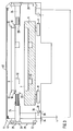
- Fig. 1 shows an embodiment of a circuit board drilling machine 1 with a base frame 2, a base plate 4 and a workpiece clamping plate 5 arranged thereon, which is axially displaceable in the Y direction.
- the drilling spindle unit (s) for drilling the circuit board packages to be arranged on the workpiece clamping plate which is adjustable in the Z and X direction (see the coordinate cross in FIG. 1), is (are) not shown in detail, since they are from one Housing 3 is (are), as is often used in technology.
- a tool magazine 7, as is customary in LP drilling machines, is often arranged at the front end of the workpiece clamping plate 5, this magazine 7 being generally referred to below as the “current” tool magazine and with the reference number 7.
- 1 further shows seven further tool magazines M1 to M6, which are located relatively closely above the workpiece clamping plate 5 on a supply level. These are also referred to below as “additional” tool magazines and sometimes also with the reference number 6.
- FIG. 2 shows the situation of FIG. 1 in a basic representation from the front, that is to say in the viewing direction against the Y axis.
- the circuit board drilling machine 1 can be seen from the front with the foremost tool magazine M1 on the storage level 6A of the magazines 6 and the current tool magazine 7 at the front edge of the workpiece clamping plate 5 or the Y slide.
- the drilling spindle unit (s) of the LP drilling machine covered by the housing 3 is again not shown in FIG. 2.
- FIG. 3 shows the current magazine 7 of the workpiece clamping plate 5 and a magazine of further magazines arranged in the storage level 6A.
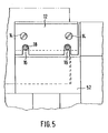
- Each of the magazines 6 is provided on each of its side running parallel to the longitudinal direction of the drill housing (in the Y direction) with a grip strip 12 which are fastened to the respective magazine with screws 14 (see FIGS. 4, 5).
- Each grip bar 12 comprises two grooves 16 (see Fig. 5) for receiving pins 18 so that each magazine M1 to M6 is stored in the storage level on a total of four pins 18 running horizontally in the X direction.
- Two pins 18 are attached to a pressure piece 20, which is connected to a piston of a pneumatic cylinder 24. Accordingly, in FIG.
- Each of the two pneumatic cylinders 24 is fastened by means of screws 26 to the respective side wall 28, which is fastened to the longitudinal side of the base plate 4 and also extends in the Y direction.
- Each side wall 28 is screwed at its lower end by means of a connecting profile 32 to a profile 34, which is preferably formed from aluminum.
- the profiles 34 are in turn fastened to the base plate 4 by means of fastening elements 36 and screws 38, 39.
- angle profiles 44 are attached by means of connecting profiles. The angle profiles 44 attached to the two side walls 28 and running parallel to these hold a cover 46 of the magazine arrangement and changing device.
- Each tool magazine 6, 7 each comprises two feet 52. As shown in FIG. 4, each foot 52 has a through bore with a bush 54, into which a dowel pin 56 can enter from below, which is on the piston rods from two in front on both sides of the center is attached to the workpiece clamping table attached lifting cylinders 60.
- the total of two lifting cylinders 60 serve to lift the magazine 7 from the workpiece clamping plate 5 to a free space on the storage level 6A or one of the new (further) magazines 6 to the workpiece clamping plate 5.
- the pneumatic lifting cylinders 60 are attached to the Y-slide 64 by a flange 66 which is located on the top of the bottom 68 of the Y-slide 64.
- the flange 66 is fastened to the base 68 by means of a fastening screw 70, while the housing of the lifting cylinder 60 is fastened to the flange by means of a fastening screw 72.
- each foot 52 In order to lock a tool magazine on the workpiece clamping plate 5 or on the Y slide 64, each foot 52 also has a bore 74 which runs in the radial direction thereof, that is to say in the X direction.
- a receptacle 76 is introduced into the bore 74, into which a piston 78 of a pneumatically actuated locking cylinder 80 can move in order to lock the foot 52 and thus also the magazine 7 against vertical movement thereof.
- each locking cylinder 80 must be firmly connected to the Y slide 64. This takes place with the aid of an intermediate piece 81, which is likewise arranged on the upper side of the base 68 of the Y-slide 64 and is fastened to the base 68 by means of a screw 82.
- the locking cylinder 80 is in turn fastened to the intermediate piece 81 by means of a screw 83.
- the lifting cylinders 60, the locking cylinders 80 and the cylinders 24 are preferably designed as compressed air cylinders which are connected to a central compressed air supply.
- sensors according to the prior art are arranged on the compressed air cylinders in order to close the intended retracted and extended positions of the compressed air cylinders control and control.
- electrical lines from the sensors to the central control are provided.
- the device shown in FIGS. 1 to 5 makes it possible that one of several tool magazines located in the supply level can be brought into a position in which it is required for the usual tool change of the LP drilling machine, and then this current " magazine can be brought back from there back to its previous position in the storage level.
- several tool magazines can be exchanged for one another, so that the number of tools ultimately available can be increased almost arbitrarily. This exchange takes place automatically and is carried out by the control unit of the circuit board drilling machine 1.
- the magazines M1 to M7 are arranged manually on the storage level of the reference numeral 6.
- Each individual magazine is coded in order to prevent incorrect placement thereof, the coding being carried out in a known manner
- This coding is achieved, for example, by means of a positive-locking connection, which ensures that a particular magazine is only ever arranged in the appropriate place in the magazine, which is of crucial importance for the correct control of the magazines.
- the Y slide 64 moves into a Y position in which the fitting cylinders 56 of the lifting cylinders 60 are located in a position just below the bushes 54 of the feet 52, which are connected to the magazine selected by the machine control in the storage level 6A. Then the lifting cylinders 60 extend upwards until the fitting cylinders 56 are completely inserted into the bushes 54. The magazine to be picked up is then released at its magazine location by the cylinders 24 retracting and the pins 18 moving out of the grooves 16. Thereupon, the lifting cylinders 60 move downward, so that the picked-up magazine is lowered.
- the magazine is then locked at its feet 52 by means of the locking cylinders 80 on the Y-slide 64 or on the workpiece clamping plate 5 arranged thereon, in that the locking cylinders 80 extend.
- the Y-carriage 64 can then together with the corresponding one current " tool magazine can be moved as required for machining the workpieces or for the tool exchange between the current magazine and the drilling spindle unit.
- the Y slide 64 In order to put a current tool magazine 7 locked with the Y slide 64 back into the intended magazine location on the supply level, the Y slide 64 extends until the tool magazine is located exactly below its (then empty) magazine position on the supply level 6A.
- the current tool magazine is then unlocked by moving the locking cylinders 80 out of their locking position.
- the lifting cylinders 60 then extend upwards to the Lift the tool magazine to its intended empty magazine location.
- the magazine holding cylinders 24 arranged on the storage level extend so that the tool magazine can be placed on the pins 18.
- the lifting cylinders 60 move in, so that the fitting cylinders 56 move completely out of the bushing 54.
- the Y-slide 64 and the lifting cylinders 60 are then able to receive another of the tool magazines 6 located on the supply level and to position them in front of the tool clamping plate 5.
- Corresponding sensors in the lifting cylinders 60 and the cylinders 24 ensure that these extend exactly in the intended length when the tool magazines are picked up or put down on the corresponding storage level, so that, for example, when the tool magazine is locked with the Y slide 64 Feet 52 are brought into the exact position that the pistons 78 can move into the bores 74.
- the control of the circuit board drilling machine 1 ensures that the lifting cylinders 60 cannot extend or retract when the locking cylinders 80 are locked.
- the described embodiment enables a very simple sequence of linear movements to pick up tool magazines and bring them to the workpiece clamping plate 5 or to bring them back from there to the supply level 6A.
- the space above the workpiece clamping plate 5 is between the front of the table and the drilling spindle used for the magazine stock, which is essentially only possible with PCB drilling machines, because they only have a very limited space requirement for the workpieces (PCB packages to be drilled) above the workpiece clamping plate 5.
- two or more storage levels located one above the other can also be provided in the area between the front of the table and the drilling spindle unit in the housing 3 above the workpiece clamping plate 5.
- a corresponding additional mechanism is then to be provided which frees access to a tool magazine which is located on one of the storage levels located further up. This could e.g. with a corresponding shift of the tool magazines on the lower levels.
- the tool magazines are then displaceably arranged on the storage levels located below the uppermost storage level.
- the magazine stocking above the workpiece clamping plate 5 could also take place with a horizontal conveyor or also with a magazine cylinder rotatable about a central axis or another device (for example a chain conveyor) for receiving a plurality of magazines.
- the tool magazines are then arranged, for example, on appropriate racks along a conveyor belt or along the circumference of the magazine cylinder.
- the Device for storing the magazine first of all the new magazine to be picked up by the lifting cylinders 60 with the aid of a motor and a corresponding control in a position in which the fitting cylinders 56 of the lifting cylinders 60 can move into the bushes 54 of the magazine to be picked up when the magazine is picked up (magazine -Change position).
- the magazine holding cylinders 24 are then retracted so that the magazine can then be lowered by retracting the lifting cylinders 60 and locked by means of the locking cylinders 80.
- the tool magazines can also be stored in a different way than in the described manner above the workpiece clamping plate or the Y-slide.
- a vertical conveyor with a number of magazines could be arranged at a suitable location in front of or to the side of the printed circuit board drilling machine 1.
- Tool magazine 7 is located in front of the workpiece clamping plate 5 (see Fig. 1).
- This tool magazine is then removed from the magazine store (i.e. the vertical conveyor) and the tool magazine is inserted into the space in front of the workpiece clamping plate in accordance with the described processes using, for example, straight-acting sliding mechanisms.
- tool magazines are arranged in a vertical line, ie the supply plane 6A of the tool magazines 6 can be perpendicular to the X axis or the Y axis be arranged.
- the corresponding selected tool magazine is folded down into the plane perpendicular to the Z axis, which corresponds to the plane of the tool magazine 7 in front of the tool clamping plate 5 (see FIG. 1).
- the Y slide 64 then moves into a position in which the fitting cylinders 56 are located exactly below the bushes 54 of the corresponding tool magazine.
- the further steps take place in the order in which they were described in the preferred embodiment with reference to FIGS. 1-6.
- the magazine changing device according to the invention has been described with reference to the circuit board drilling and milling machine shown in FIGS. 1, 2.
- the described principles of the magazine arrangement and changing device according to the invention can also be applied in a corresponding manner to differently designed circuit board drilling and milling machines.
Landscapes
- Engineering & Computer Science (AREA)
- Mechanical Engineering (AREA)
- Automatic Tool Replacement In Machine Tools (AREA)
Applications Claiming Priority (2)
| Application Number | Priority Date | Filing Date | Title |
|---|---|---|---|
| DE19616215 | 1996-04-23 | ||
| DE19616215A DE19616215A1 (de) | 1996-04-23 | 1996-04-23 | Werkzeugmagazin-Anordnung und -Wechselvorrichtung für Leiterplatten-Koordinatenbohrmaschinen |
Publications (1)
| Publication Number | Publication Date |
|---|---|
| EP0803318A1 true EP0803318A1 (fr) | 1997-10-29 |
Family
ID=7792214
Family Applications (1)
| Application Number | Title | Priority Date | Filing Date |
|---|---|---|---|
| EP97103757A Withdrawn EP0803318A1 (fr) | 1996-04-23 | 1997-03-06 | Magasin d'outils et dispositif de changement pour machines à percer travaillant en coordonnées pour plaques à circuit imprimé |
Country Status (2)
| Country | Link |
|---|---|
| EP (1) | EP0803318A1 (fr) |
| DE (1) | DE19616215A1 (fr) |
Cited By (3)
| Publication number | Priority date | Publication date | Assignee | Title |
|---|---|---|---|---|
| CN112719337A (zh) * | 2020-12-30 | 2021-04-30 | 深圳市大族数控科技股份有限公司 | 一种自动换刀装置及钻孔机 |
| CN115256516A (zh) * | 2021-04-29 | 2022-11-01 | 达航科技股份有限公司 | 钻孔机的夹板装置及夹持方法 |
| CN119910472A (zh) * | 2025-04-02 | 2025-05-02 | 冈田智能(江苏)股份有限公司 | 一种立式倒置平移刀库智能防护方法及系统 |
Citations (3)
| Publication number | Priority date | Publication date | Assignee | Title |
|---|---|---|---|---|
| SU1227410A1 (ru) * | 1984-07-20 | 1986-04-30 | Предприятие П/Я М-5149 | Станок с автоматической сменой инструментов |
| JPS63237832A (ja) * | 1987-03-25 | 1988-10-04 | Hitachi Seiko Ltd | ドリルパレツトの交換装置 |
| JPH04354643A (ja) * | 1991-05-31 | 1992-12-09 | Hitachi Seiko Ltd | プリント基板穴明機におけるドリル供給装置 |
Family Cites Families (4)
| Publication number | Priority date | Publication date | Assignee | Title |
|---|---|---|---|---|
| US4715108A (en) * | 1985-03-07 | 1987-12-29 | Toshiba Kikai Kabushiki Kaisha | Machine tool capable of changing worn cutting tools, such as small diameter drills, with new ones |
| DE3713046A1 (de) * | 1987-04-16 | 1988-10-27 | Kaufbeurer Leiterplatten | Werkzeugwechselanordnung fuer leiterplatten-koordinatenbohrmaschinen |
| DE4028503A1 (de) * | 1990-09-07 | 1992-03-12 | Hitachi Seiko Kk | Werkzeughaltevorrichtung, damit zusammenwirkender werkzeugwechsler und sie verwendende platinenbearbeitungsmaschine |
| IT1251252B (it) * | 1991-11-08 | 1995-05-05 | Pluritec Italia | Dispositivo di cambio automatico dell'utensile per una macchina utensile per la lavorazione di piastre di circuiti stampati. |
-
1996
- 1996-04-23 DE DE19616215A patent/DE19616215A1/de not_active Withdrawn
-
1997
- 1997-03-06 EP EP97103757A patent/EP0803318A1/fr not_active Withdrawn
Patent Citations (3)
| Publication number | Priority date | Publication date | Assignee | Title |
|---|---|---|---|---|
| SU1227410A1 (ru) * | 1984-07-20 | 1986-04-30 | Предприятие П/Я М-5149 | Станок с автоматической сменой инструментов |
| JPS63237832A (ja) * | 1987-03-25 | 1988-10-04 | Hitachi Seiko Ltd | ドリルパレツトの交換装置 |
| JPH04354643A (ja) * | 1991-05-31 | 1992-12-09 | Hitachi Seiko Ltd | プリント基板穴明機におけるドリル供給装置 |
Cited By (4)
| Publication number | Priority date | Publication date | Assignee | Title |
|---|---|---|---|---|
| CN112719337A (zh) * | 2020-12-30 | 2021-04-30 | 深圳市大族数控科技股份有限公司 | 一种自动换刀装置及钻孔机 |
| CN112719337B (zh) * | 2020-12-30 | 2022-08-19 | 深圳市大族数控科技股份有限公司 | 一种自动换刀装置及钻孔机 |
| CN115256516A (zh) * | 2021-04-29 | 2022-11-01 | 达航科技股份有限公司 | 钻孔机的夹板装置及夹持方法 |
| CN119910472A (zh) * | 2025-04-02 | 2025-05-02 | 冈田智能(江苏)股份有限公司 | 一种立式倒置平移刀库智能防护方法及系统 |
Also Published As
| Publication number | Publication date |
|---|---|
| DE19616215A1 (de) | 1997-10-30 |
Similar Documents
| Publication | Publication Date | Title |
|---|---|---|
| EP0287071B1 (fr) | Dispositif de changement d'outil pour machines à percer travaillant en coordonnées pour plaques à circuit imprimé | |
| EP3535092B1 (fr) | Machine de pierrage avec une pluralité de postes de travail | |
| DE102007060586B4 (de) | Vorrichtung zur Bearbeitung von Profilen | |
| DE2426063A1 (de) | Werkzeug-wechselvorrichtung | |
| DE102010047287B4 (de) | Verfahren zum Bearbeiten eines Werkstücks | |
| DE102009011676B4 (de) | Bearbeitungsmaschine | |
| EP3663035B1 (fr) | Machine-outil dotée d'une broche porte-outil et d'un portique de chargement | |
| DE4031911A1 (de) | Vorrichtung zum bearbeiten von stangen | |
| DE102016102996A1 (de) | Werkzeugmagazin | |
| EP3535089A1 (fr) | Centre d'usinage pour l'usinage de pièces | |
| DE19818663A1 (de) | Werkzeugmaschine | |
| EP0803318A1 (fr) | Magasin d'outils et dispositif de changement pour machines à percer travaillant en coordonnées pour plaques à circuit imprimé | |
| DE8531605U1 (de) | Werkzeugmaschine, insbesondere zum Bohren und Fräsen von Leiterplatten | |
| DE1502010A1 (de) | Werkzeugmaschine mit automatischem Werkzeugwechsel | |
| DE102006058221A1 (de) | Werkzeugmaschine zum spanabhebenden Bearbeiten von Werkstücken | |
| AT507328B1 (de) | Werkzeugmaschine | |
| DE102019124034B4 (de) | Werkzeugmaschine mit Werzeugwechselmagazin und zugeordnetem Werkzeugspeichermagazin | |
| DE29825149U1 (de) | Werkzeugmaschine mit Werkstückwechseleinrichtung | |
| DE19607883A1 (de) | Vertikal-Drehmaschine | |
| DE10336156B4 (de) | Bearbeitungsmaschine | |
| DE4315997A1 (de) | Vorrichtung zum automatischen Wechseln der Werkzeuge im Bohrkopf einer Plattenbohrmaschine | |
| DE102008005956B4 (de) | Bearbeitungszentrum mit Werkstückwechsler und Rüstplatz | |
| DE202005012039U1 (de) | Handhabungsgerät für zumindest eine Bearbeitungsmaschine | |
| DE102020002319A1 (de) | Spanneinrichtung für Werkstücke aus Holz, Kunststoff, Aluminium und dergleichen sowie Anlage mit einer solchen Spanneinrichtung | |
| EP1754562B1 (fr) | Dispositif de forage simultané de plusieurs trous coaxiales |
Legal Events
| Date | Code | Title | Description |
|---|---|---|---|
| PUAI | Public reference made under article 153(3) epc to a published international application that has entered the european phase |
Free format text: ORIGINAL CODE: 0009012 |
|
| 17P | Request for examination filed |
Effective date: 19970821 |
|
| AK | Designated contracting states |
Kind code of ref document: A1 Designated state(s): CH DE FR GB IT LI |
|
| RAP1 | Party data changed (applicant data changed or rights of an application transferred) |
Owner name: KLINGELNBERG SOEHNE LEITERPLATTENTECHNIK GMBH |
|
| 17Q | First examination report despatched |
Effective date: 20010412 |
|
| STAA | Information on the status of an ep patent application or granted ep patent |
Free format text: STATUS: THE APPLICATION HAS BEEN WITHDRAWN |
|
| 18W | Application withdrawn |
Withdrawal date: 20010813 |