EP0802721B1 - Procede permettant de separer des produits individuels de la traite - Google Patents
Procede permettant de separer des produits individuels de la traite Download PDFInfo
- Publication number
- EP0802721B1 EP0802721B1 EP95935943A EP95935943A EP0802721B1 EP 0802721 B1 EP0802721 B1 EP 0802721B1 EP 95935943 A EP95935943 A EP 95935943A EP 95935943 A EP95935943 A EP 95935943A EP 0802721 B1 EP0802721 B1 EP 0802721B1
- Authority
- EP
- European Patent Office
- Prior art keywords
- line
- milk
- milking
- separating
- shut
- Prior art date
- Legal status (The legal status is an assumption and is not a legal conclusion. Google has not performed a legal analysis and makes no representation as to the accuracy of the status listed.)
- Expired - Lifetime
Links
- 210000004080 milk Anatomy 0.000 title claims description 56
- 235000013336 milk Nutrition 0.000 title claims description 56
- 239000008267 milk Substances 0.000 title claims description 54
- 241000283690 Bos taurus Species 0.000 title claims 3
- 238000011010 flushing procedure Methods 0.000 description 7
- 239000007788 liquid Substances 0.000 description 2
- 238000007726 management method Methods 0.000 description 2
- 238000000034 method Methods 0.000 description 2
- 238000000926 separation method Methods 0.000 description 2
- 239000000243 solution Substances 0.000 description 2
- 244000052616 bacterial pathogen Species 0.000 description 1
- 238000009795 derivation Methods 0.000 description 1
- 239000003599 detergent Substances 0.000 description 1
- 244000144980 herd Species 0.000 description 1
- 239000012487 rinsing solution Substances 0.000 description 1
- 238000005204 segregation Methods 0.000 description 1
- 230000001960 triggered effect Effects 0.000 description 1
- 238000005406 washing Methods 0.000 description 1
Images


Classifications
-
- B—PERFORMING OPERATIONS; TRANSPORTING
- B08—CLEANING
- B08B—CLEANING IN GENERAL; PREVENTION OF FOULING IN GENERAL
- B08B9/00—Cleaning hollow articles by methods or apparatus specially adapted thereto
- B08B9/02—Cleaning pipes or tubes or systems of pipes or tubes
- B08B9/027—Cleaning the internal surfaces; Removal of blockages
- B08B9/032—Cleaning the internal surfaces; Removal of blockages by the mechanical action of a moving fluid, e.g. by flushing
- B08B9/0321—Cleaning the internal surfaces; Removal of blockages by the mechanical action of a moving fluid, e.g. by flushing using pressurised, pulsating or purging fluid
-
- A—HUMAN NECESSITIES
- A01—AGRICULTURE; FORESTRY; ANIMAL HUSBANDRY; HUNTING; TRAPPING; FISHING
- A01J—MANUFACTURE OF DAIRY PRODUCTS
- A01J5/00—Milking machines or devices
- A01J5/04—Milking machines or devices with pneumatic manipulation of teats
- A01J5/044—Milk lines or coupling devices for milk conduits
Definitions
- the invention relates to a device for separation of milks from milking clusters in milking systems, with a control unit, a separating tank and a switching device for the optional connection of a milking line with a milk pipe or one to the separating tank leading supply line.
- Such a device is known for example from DE 40 07 327 C1. In doing so, milks with high content at harmful germs separated from the bulk milk and in a special separator tank headed. An automatic Emptying of the separating tank is in the known Device not provided.
- the invention has for its object a device to create that allows a subset or all of it Automatically discharge milk from the milking system.
- This object is achieved in that the separating container connected to the milk line via a connecting line and a first drain line of the separation container with a feed pump and a first check valve is provided.
- the negative pressure of the milk line is via the connecting line transferred to the separator tank so that the Milk to be separated is sucked into the separating tank when the milking line is switched over is connected to the inlet pipe.
- the actuation of the Switching device takes place depending on the control unit of predetermined criteria.
- the first check valve in the drain line of the separator tank closes at negative pressure and thus prevents entry from atmosphere via the first drain line into the separating tank.
- the object can also be achieved in that the separating container with the milk line via a connecting line is connected in the valve device is arranged, which is in connection with the atmosphere stands, with a first drain line of the separating container is provided with a first check valve.
- the separator tank is replaced by the Valve device connected to the milk line if the milk is to be drawn off via the feed line.
- the milking line is connected to the Switching device with the milk line and the separating tank via the valve device with the atmosphere connected, which creates atmospheric pressure in the separating tank builds up and the opening of the first check valve allows the milking to proceed.
- the switching device formed by a shut-off valve in the milking line and a second check valve in the feed line.
- the second check valve opens automatically when the separating tank via the valve device with the Negative pressure in the milk line is connected.
- the Switching device formed by a first switching unit for optional connection of the milking line with the supply line or one equipped with a first shut-off device second drain line and a second switchover unit for optional connection of the milking line with the Milk line or one with a second shut-off device provided flushing line.
- This switching device enables simultaneously rinsing the device when the Milking line simultaneously with the second drain line and is connected to the flushing line.
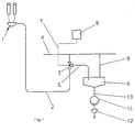
- FIG. 1 in FIG. 1 denotes a milking cluster, of which a milking line 2 with a switching device 3 to one Milk line 4 leads.
- the switching device 3 is via an inlet line 5 with a separating tank 6 and connected to a control unit 8 via a line 7.
- the separating tank 6 is connected via a connecting line 9 in connection with the milk line 4.
- a Delivery pump 11 and a first check valve 12 are arranged in a first drain line 10 of the separating tank 6 .
- the milking line 2 In normal milk withdrawal, the milking line 2 is over the Switching device 3 connected to the milk line 4, the feed line 5 to the separating tank 6 being shut off is. The milk then flows through the milk line 4 in a milk container, not shown. As soon as 8 criteria are reported to the control unit, the the milking management will request segregation of the milking 2 via the switchover device 3 with the feed line 5 connected and the milk now flows into the separating tank 6, which with the connecting line 9 the negative pressure of the milk line 4 is applied. To discharge the milk, the feed pump 11 is switched on, the negative pressure in the separating tank 6 overcomes and their flow rate the first check valve 12 opens automatically.
- a valve device 13 is provided in the connecting line 9, which can act upon the separating container 6 either with the negative pressure of the milk line 4 or with atmospheric pressure.
- the milking line 2 is connected to the supply line 5 via the control unit 8 and the separating tank 6 is connected to the milk line 4 via the valve device 13.
- the milking line 2 is connected again to the milk line 4 via the switching device 3 and the separating container 6 is connected to the atmosphere via the valve device 13.
- the first check valve 12 opens at atmospheric pressure and thus enables the separating container 6 to be emptied.
- a feed pump for emptying the separating container 6 can be dispensed with.
- the device according to FIG. 3 includes a switching device 3, which is formed by a shut-off valve 14 in the milking line 2 and a second check valve 15 in the feed line 5.
- a switching device 3 which is formed by a shut-off valve 14 in the milking line 2 and a second check valve 15 in the feed line 5.
- the shut-off valve 14 is open and the separating container 6 is acted upon by the valve device 13 with atmosphere.
- the second check valve 15 in the feed line 5 closes automatically.
- the first check valve 12 in the first drain line 10 is now open and enables the separating container 6 to be emptied.
- the shut-off valve 14 is closed via the control unit 8 and the separating container 6 is connected to the negative pressure of the milk line 4 via the valve device 13.
- the second check valve 15 opens automatically and the first check valve 12 closes.
- the milk is now fed into the separating tank 6 via the feed line 5.
- the separating container 6 is automatically emptied through the opening of the first check valve 12.
- the milking line 2 can be selectively connected to the inlet line 5 or a second outlet line 18 provided with a first shut-off device 17 by a first switching unit 16 and optionally with the milk line 4 or one having a second shut-off device 20 by a second switching unit 19 provided rinsing line 21 are connected.
- the milking line 2 is connected to the second drain line 18 via the first switchover unit 16 and to the milk line 4 via the second switchover unit 19.
- the first shut-off device 17 closes automatically.
- the milk thus flows into the milk line 4.
- the milking line 2 is connected to the supply line 5 via the first switchover unit 16 and to the flushing line 21 via the second switchover unit 19.
- the shut-off device 20 in the flushing line 21 is closed.
- the milk can therefore only get into the separating container 6, from which it is discharged by switching on the feed pump 11.
- the milking line 2 is connected to the second drain line 18 via the first switchover unit 16 and to the flushing line 21 via the second switchover unit 19.
- the washing-up liquid is conveyed via the washing line 21 and the milking line 2 to the milking cluster 1.
- a part of the rinsing solution flows via the first switching unit 16 into the second drain line 18, the second shut-off device 17 of which opens automatically due to the pressure of the detergent.
- the switching states described can be triggered by the control unit 8.
Landscapes
- Life Sciences & Earth Sciences (AREA)
- Engineering & Computer Science (AREA)
- Mechanical Engineering (AREA)
- Animal Husbandry (AREA)
- Environmental Sciences (AREA)
- External Artificial Organs (AREA)
- Dairy Products (AREA)
Claims (4)
- Dispositif de séparation des traites provenant de faisceaux trayeurs (1) dans des installations de traite, muni d'une unité de commande (8), d'une cuve de séparation (6) et d'un dispositif de commutation (3) pouvant relier une conduite de traite (2) soit à une tuyauterie à lait (4) soit à une conduite d'alimentation (5) menant vers la cuve de séparation (6) caractérisé en ce que la cuve de séparation (6) est reliée la tuyauterie à lait (4) par une ligne de raccordement (9), et qu'une première conduite d'écoulement (10) de la cuve de séparation (6) est munie d'une pompe (11) et d'un premier clapet anti-retour (12).
- Dispositif de séparation des traites provenant de faisceaux trayeurs (1) dans des installations de traite, muni d'une unité de commande (8), d'une cuve de séparation (6) et d'un dispositif de commutation (3) pouvant relier une conduite de traite (2) soit à une tuyauterie à lait (4) soit à une conduite d'alimentation (5) menant vers la cuve de séparation (6), caractérisé en ce que la cuve de séparation (6) est reliée à la tuyauterie de lait (4) par une ligne de raccordement (9) comportant une vanne (13) communiquant avec l'atmosphère, une première conduite d'écoulement (10) de la cuve de séparation (6) étant munie d'un premier clapet anti-retour (12).
- Dispositif selon revendication 2, caractérisé en ce que le dispositif de commutation (3) est constitué par une vanne d'arrêt (14) incorporée dans la conduite de traite (2) et par un premier clapet anti-retour (15) incorporé dans la conduite d'alimentation (5).
- Dispositif selon revendication 1, caractérisé en ce que le dispositif de commutation (3) est constitué par une première unité de commutation (16) assurant la liaison de la conduite de traite (2) soit à la conduite d'alimentation (5) soit à une seconde conduite d'écoulement (19) comportant un premier organe d'arrêt (17) et par une seconde unité de commutation (19) pouvant relier la conduite de traite (2) soit à la tuyauterie à lait (4) soit à une conduite de rinçage (21) munie d'un second organe d'arrêt (20).
Applications Claiming Priority (3)
| Application Number | Priority Date | Filing Date | Title |
|---|---|---|---|
| DE19502688 | 1995-01-28 | ||
| DE19502688A DE19502688C1 (de) | 1995-01-28 | 1995-01-28 | Vorrichtung zur Separierung von Gemelken |
| PCT/EP1995/004078 WO1996022679A1 (fr) | 1995-01-28 | 1995-10-17 | Procede permettant de separer des produits individuels de la traite |
Publications (2)
| Publication Number | Publication Date |
|---|---|
| EP0802721A1 EP0802721A1 (fr) | 1997-10-29 |
| EP0802721B1 true EP0802721B1 (fr) | 1998-08-26 |
Family
ID=7752547
Family Applications (1)
| Application Number | Title | Priority Date | Filing Date |
|---|---|---|---|
| EP95935943A Expired - Lifetime EP0802721B1 (fr) | 1995-01-28 | 1995-10-17 | Procede permettant de separer des produits individuels de la traite |
Country Status (4)
| Country | Link |
|---|---|
| EP (1) | EP0802721B1 (fr) |
| DE (2) | DE19502688C1 (fr) |
| IL (1) | IL116794A (fr) |
| WO (1) | WO1996022679A1 (fr) |
Families Citing this family (6)
| Publication number | Priority date | Publication date | Assignee | Title |
|---|---|---|---|---|
| DE19636314C1 (de) * | 1996-09-06 | 1998-04-09 | Westfalia Landtechnik Gmbh | Melkvorrichtung mit einer Überwachungseinrichtung und ein Verfahren zum Überwachen einer Melkvorrichtung |
| DE19651005C2 (de) * | 1996-11-29 | 2001-12-13 | Gascoigne Melotte Deutschland | Anordnung zur Ableitung von als nicht verkehrsfähig bestimmter Milch bei Melkanlagen |
| DE10312807A1 (de) | 2002-03-21 | 2004-02-12 | Westfaliasurge Gmbh | Aerosolfilter |
| NL1030703C2 (nl) * | 2005-12-19 | 2007-06-20 | Lely Entpr Ag | Werkwijze en inrichting voor het melken van een dier. |
| DE102015100489A1 (de) * | 2015-01-14 | 2016-07-14 | Eugster/Frismag Ag | Getränkezubereitungsvorrichtung sowie Betriebsverfahren |
| DE102015100488A1 (de) * | 2015-01-14 | 2016-07-14 | Eugster/Frismag Ag | Getränkezubereitungsvorrichtung sowie Betriebsverfahren |
Family Cites Families (1)
| Publication number | Priority date | Publication date | Assignee | Title |
|---|---|---|---|---|
| DE4007327C1 (fr) * | 1990-03-08 | 1991-07-11 | Lang Apparatebau Gmbh, 8227 Siegsdorf, De |
-
1995
- 1995-01-28 DE DE19502688A patent/DE19502688C1/de not_active Expired - Fee Related
- 1995-10-17 EP EP95935943A patent/EP0802721B1/fr not_active Expired - Lifetime
- 1995-10-17 WO PCT/EP1995/004078 patent/WO1996022679A1/fr not_active Ceased
- 1995-10-17 DE DE59503390T patent/DE59503390D1/de not_active Expired - Fee Related
-
1996
- 1996-01-17 IL IL11679496A patent/IL116794A/en not_active IP Right Cessation
Also Published As
| Publication number | Publication date |
|---|---|
| EP0802721A1 (fr) | 1997-10-29 |
| IL116794A0 (en) | 1996-05-14 |
| DE19502688C1 (de) | 1996-01-18 |
| WO1996022679A1 (fr) | 1996-08-01 |
| IL116794A (en) | 1998-12-06 |
| DE59503390D1 (de) | 1998-10-01 |
Similar Documents
| Publication | Publication Date | Title |
|---|---|---|
| DE2912303C2 (de) | Luft- und Wasserversorgungsgerät für ein Endoskop | |
| DE69109012T2 (de) | Vorrichtung zum Auflösen eines Korrekturmediums einer dialytischen Lösung. | |
| EP3083087A1 (fr) | Dispositif de nettoyage et procédé de nettoyage de récipients | |
| DE102019001471A1 (de) | Saugfördersystem für Schüttgut, insbesondere Kunststoffgranulat | |
| EP0062339A2 (fr) | Installation pour récupérer des résidus de béton | |
| DE19502688C1 (de) | Vorrichtung zur Separierung von Gemelken | |
| DE4105568C2 (de) | Filteranordnung für Flüssigkeiten mit Schwebeteilchen | |
| EP0161552B1 (fr) | Procédé pour prendre un échantillon représentatif de lait d'un volume de lait plus grand et dispositif à cet effet | |
| DE69416542T2 (de) | Vorrichtung zum Melken von Tieren | |
| EP1650169B1 (fr) | Dispositif de clarification biologique avec une pompe immergée | |
| DE69416340T2 (de) | Vorrichtung zum Melken von Tieren | |
| EP0160933B1 (fr) | Machine à traire avec collecteur | |
| DE19520916A1 (de) | Einrichtung zur Versorgung von Hämodialysegeräten mit Dialysierflüssigkeit | |
| DE19639957A1 (de) | Regenwassernutzungsanlage | |
| EP4676286A1 (fr) | Machine de distribution de boisson avec dispositif de nettoyage | |
| EP0417579B1 (fr) | Réservoir d'égalisation de pression pour concentré d'hémodialyse | |
| DE3826461C1 (en) | Method and device for the centrifugal sterilisation of milk | |
| EP0709666B1 (fr) | Dispositif pour la prise d'un échantillon représentatif de lait | |
| EP1350884B1 (fr) | Dispositif de vidange d'eau pour machine à laver | |
| EP0088165B1 (fr) | Appareil de rinçage automatique pour installations de traite | |
| DE29616912U1 (de) | Regenwassernutzungsanlage | |
| DE3809473A1 (de) | Reinigungseinrichtung in anlagen fuer die synthese von chemischen verbindungen, die reinigungseinrichtung enthaltende anlage und verfahren zur reinigung der letzteren | |
| DE2917883A1 (de) | Verfahren und vorrichtung zum entleeren von abscheideranlagen fuer abwaesser | |
| DE10316585A1 (de) | Verfahren zum Reinigen der milchführenden Teile einer Melkvorrichtung sowie Melkvorrichtung mit einer Einrichtung zum Reinigen der milchführenden Teile | |
| DE3422452A1 (de) | Vorrichtung zur entleerung einer milchleitung |
Legal Events
| Date | Code | Title | Description |
|---|---|---|---|
| PUAI | Public reference made under article 153(3) epc to a published international application that has entered the european phase |
Free format text: ORIGINAL CODE: 0009012 |
|
| 17P | Request for examination filed |
Effective date: 19970516 |
|
| AK | Designated contracting states |
Kind code of ref document: A1 Designated state(s): DE NL SE |
|
| GRAG | Despatch of communication of intention to grant |
Free format text: ORIGINAL CODE: EPIDOS AGRA |
|
| GRAG | Despatch of communication of intention to grant |
Free format text: ORIGINAL CODE: EPIDOS AGRA |
|
| GRAH | Despatch of communication of intention to grant a patent |
Free format text: ORIGINAL CODE: EPIDOS IGRA |
|
| GRAH | Despatch of communication of intention to grant a patent |
Free format text: ORIGINAL CODE: EPIDOS IGRA |
|
| 17Q | First examination report despatched |
Effective date: 19980210 |
|
| GRAA | (expected) grant |
Free format text: ORIGINAL CODE: 0009210 |
|
| AK | Designated contracting states |
Kind code of ref document: B1 Designated state(s): DE NL SE |
|
| REF | Corresponds to: |
Ref document number: 59503390 Country of ref document: DE Date of ref document: 19981001 |
|
| PLBQ | Unpublished change to opponent data |
Free format text: ORIGINAL CODE: EPIDOS OPPO |
|
| PLBI | Opposition filed |
Free format text: ORIGINAL CODE: 0009260 |
|
| PLBF | Reply of patent proprietor to notice(s) of opposition |
Free format text: ORIGINAL CODE: EPIDOS OBSO |
|
| 26 | Opposition filed |
Opponent name: PROLION B.V. Effective date: 19990526 |
|
| PLBF | Reply of patent proprietor to notice(s) of opposition |
Free format text: ORIGINAL CODE: EPIDOS OBSO |
|
| PLBO | Opposition rejected |
Free format text: ORIGINAL CODE: EPIDOS REJO |
|
| APAC | Appeal dossier modified |
Free format text: ORIGINAL CODE: EPIDOS NOAPO |
|
| APAE | Appeal reference modified |
Free format text: ORIGINAL CODE: EPIDOS REFNO |
|
| APAC | Appeal dossier modified |
Free format text: ORIGINAL CODE: EPIDOS NOAPO |
|
| APAC | Appeal dossier modified |
Free format text: ORIGINAL CODE: EPIDOS NOAPO |
|
| PLCK | Communication despatched that opposition was rejected |
Free format text: ORIGINAL CODE: EPIDOSNREJ1 |
|
| PLBN | Opposition rejected |
Free format text: ORIGINAL CODE: 0009273 |
|
| STAA | Information on the status of an ep patent application or granted ep patent |
Free format text: STATUS: OPPOSITION REJECTED |
|
| 27O | Opposition rejected |
Effective date: 20030626 |
|
| NLR2 | Nl: decision of opposition |
Effective date: 20030626 |
|
| APAH | Appeal reference modified |
Free format text: ORIGINAL CODE: EPIDOSCREFNO |
|
| PGFP | Annual fee paid to national office [announced via postgrant information from national office to epo] |
Ref country code: NL Payment date: 20081028 Year of fee payment: 14 |
|
| PGFP | Annual fee paid to national office [announced via postgrant information from national office to epo] |
Ref country code: DE Payment date: 20081103 Year of fee payment: 14 |
|
| PGFP | Annual fee paid to national office [announced via postgrant information from national office to epo] |
Ref country code: SE Payment date: 20081023 Year of fee payment: 14 |
|
| REG | Reference to a national code |
Ref country code: NL Ref legal event code: V1 Effective date: 20100501 |
|
| EUG | Se: european patent has lapsed | ||
| PG25 | Lapsed in a contracting state [announced via postgrant information from national office to epo] |
Ref country code: NL Free format text: LAPSE BECAUSE OF NON-PAYMENT OF DUE FEES Effective date: 20100501 Ref country code: DE Free format text: LAPSE BECAUSE OF NON-PAYMENT OF DUE FEES Effective date: 20100501 |
|
| PG25 | Lapsed in a contracting state [announced via postgrant information from national office to epo] |
Ref country code: SE Free format text: LAPSE BECAUSE OF NON-PAYMENT OF DUE FEES Effective date: 20091018 |
|
| REG | Reference to a national code |
Ref country code: DE Ref legal event code: R081 Ref document number: 59503390 Country of ref document: DE Owner name: GEA MECHANICAL EQUIPMENT GMBH, DE Free format text: FORMER OWNER: WESTFALIA SEPARATOR AG, 59302 OELDE, DE Effective date: 20140507 |