EP0802685A2 - Einplatten-LCD Anzeigegerät - Google Patents
Einplatten-LCD Anzeigegerät Download PDFInfo
- Publication number
- EP0802685A2 EP0802685A2 EP97105927A EP97105927A EP0802685A2 EP 0802685 A2 EP0802685 A2 EP 0802685A2 EP 97105927 A EP97105927 A EP 97105927A EP 97105927 A EP97105927 A EP 97105927A EP 0802685 A2 EP0802685 A2 EP 0802685A2
- Authority
- EP
- European Patent Office
- Prior art keywords
- liquid crystal
- light
- macro
- single plate
- display apparatus
- Prior art date
- Legal status (The legal status is an assumption and is not a legal conclusion. Google has not performed a legal analysis and makes no representation as to the accuracy of the status listed.)
- Granted
Links
Images


Classifications
-
- H—ELECTRICITY
- H04—ELECTRIC COMMUNICATION TECHNIQUE
- H04N—PICTORIAL COMMUNICATION, e.g. TELEVISION
- H04N9/00—Details of colour television systems
- H04N9/12—Picture reproducers
- H04N9/31—Projection devices for colour picture display, e.g. using electronic spatial light modulators [ESLM]
- H04N9/3102—Projection devices for colour picture display, e.g. using electronic spatial light modulators [ESLM] using two-dimensional electronic spatial light modulators
- H04N9/3111—Projection devices for colour picture display, e.g. using electronic spatial light modulators [ESLM] using two-dimensional electronic spatial light modulators for displaying the colours sequentially, e.g. by using sequentially activated light sources
- H04N9/3114—Projection devices for colour picture display, e.g. using electronic spatial light modulators [ESLM] using two-dimensional electronic spatial light modulators for displaying the colours sequentially, e.g. by using sequentially activated light sources by using a sequential colour filter producing one colour at a time
-
- G—PHYSICS
- G02—OPTICS
- G02B—OPTICAL ELEMENTS, SYSTEMS OR APPARATUS
- G02B5/00—Optical elements other than lenses
- G02B5/18—Diffraction gratings
- G02B5/1866—Transmission gratings characterised by their structure, e.g. step profile, contours of substrate or grooves, pitch variations, materials
-
- G—PHYSICS
- G02—OPTICS
- G02F—OPTICAL DEVICES OR ARRANGEMENTS FOR THE CONTROL OF LIGHT BY MODIFICATION OF THE OPTICAL PROPERTIES OF THE MEDIA OF THE ELEMENTS INVOLVED THEREIN; NON-LINEAR OPTICS; FREQUENCY-CHANGING OF LIGHT; OPTICAL LOGIC ELEMENTS; OPTICAL ANALOGUE/DIGITAL CONVERTERS
- G02F1/00—Devices or arrangements for the control of the intensity, colour, phase, polarisation or direction of light arriving from an independent light source, e.g. switching, gating or modulating; Non-linear optics
- G02F1/01—Devices or arrangements for the control of the intensity, colour, phase, polarisation or direction of light arriving from an independent light source, e.g. switching, gating or modulating; Non-linear optics for the control of the intensity, phase, polarisation or colour
- G02F1/13—Devices or arrangements for the control of the intensity, colour, phase, polarisation or direction of light arriving from an independent light source, e.g. switching, gating or modulating; Non-linear optics for the control of the intensity, phase, polarisation or colour based on liquid crystals, e.g. single liquid crystal display cells
- G02F1/133—Constructional arrangements; Operation of liquid crystal cells; Circuit arrangements
- G02F1/1333—Constructional arrangements; Manufacturing methods
- G02F1/1335—Structural association of cells with optical devices, e.g. polarisers or reflectors
- G02F1/1336—Illuminating devices
- G02F1/133621—Illuminating devices providing coloured light
Definitions
- reference numeral 1 denotes single plate type color liquid crystal panel means
- 2 denotes three-primary-color pixels
- 3 denotes light-input-side lenses forming three-position means for converging input three rays of each primary color coming from three directions to respective color positions at every trio-pixel pitch
- 23 denotes a block collectively representing a light source and collimator means.
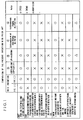
- Reference numeral 5 denotes macroscopically flat diffracting plate means
- 6 denotes a diffraction grating formed on the outgoing plane of the diffracting plate means
- 7 denotes incident white light
- 7' denotes the direction of a zero-order light output from the diffracting plate.
- R, G and B represent red, green and blue light rays, but they may sometimes be referred to as R ray and so on for short.
- Reference numerals 8, 8' and 8'' denote G ray, R ray and B ray of the first-order diffracted light output from the diffracting plate.
- the deflection angle ⁇ G it is very difficult in the prior art to set the deflection angle ⁇ G to be 10° or less when the R-G separation angle is 0.05 rad or larger.
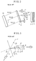
- the value is 1.0 instead of 1.6, all three rays, including the red ray and the blue ray, besides the green ray, are matched (coincide) with the liquid crystal elements. However, because the above value is 1.6, the red ray and the blue ray are not matched with the target liquid crystal elements as shown in Fig. 5. In other words, the utilization efficiency of the red and blue light ray deteriorates.
- Fig. 5 shows only one period of the trio pixel array.
- reference numerals 2 and 6' denote same things as already described, 14, 15 and 16 denote the first order diffracted G rays, 17, 18 and 19 denote the first order diffracted R rays, and 20, 21 and 22 denote the first order B rays.
- R and B component rays of the principal ray striking the center of each pitch of the diffraction grating 6' are both correctly incident on the target pixels.
- the marginal rays corresponding to both end portions of each pitch are unable to be incident on the target pixels due to deviation loss.
- thermonuclear power generation can be realized easily.
- An object of the present invention is to provide a single plate type color liquid crystal display apparatus featuring the improved transmission efficiency.
- Yet another object of the present invention is to provide a new-fangled optical system for reducing nearly in half a substantial increase of the light diverging angle caused by the R-G separation angle by the light diffracting means.
- Another object of the present invention is to provide a compact space-saving or light-weight liquid crystal display apparatus.
- both types [1] and [2] in Fig. 1 of the liquid crystal display include common novel light diffracting means, and the novel light diffracting means is, at its macroscopic level, a three-dimensional unflat plate form with a macro structural periodicity having at least either macro prisms or a macro lenticular face, together with multi-stepped diffraction gratings at its microscopic level.
- the display apparatus is in a shape having prisms at its macroscopic level, and also includes light diffracting means having a diffraction grating formed on an oblique side face of each prism at its microscopic level.
- the light diffracting means serves to cancel its angle of deflection by its macro prisms. Therefore, the R-G separation angle can be set at 3° or larger, and the deflection angle of G ray can be set at 20° or less. The reduction of the deflection angle is effective in reducing the volume of the cabinet for housing the optical system.
- the light diffracting means is formed with a macro lenticular face, and the pitch of array of the lenticular elements is selected so as to be equal to the pitch of trio pixel array of the liquid crystal panel.
- the lenticular structure enables the G rays emerging from the diffraction grating to converge to the G pixels.
- the pitch of the diffraction grating array is set to obtain an adequate G-R separation angle ⁇ independently of the modulated pitch of the diffraction direction of G rays. Therefore, by overcoming the condition of constraint in the above-mentioned equation (16), it becomes possible to make compatible the convergence of R, G and B rays to the target pixels by the light diffracting means.
- the light transmission efficiency and the chromatic purity can be improved, and therefore, and therefore the picture quality can be enhanced.
- collimator means for reducing the light diverging angle is installed at the rear of the diffraction grating.
- the focal plane of the collimator means is selected so as to substantially coincide with the diffraction grating (accuracy within about ⁇ 30%). Therefore, the rays incident on the same point of the diffraction grating emerge as parallel rays from the collimator means. Consequently, the light diverging angle can be decreased.
- projection lens means is placed at the rear of the liquid crystal panel means, this method is effective in reducing the aperture and the weight of the projection lens means.
- the liquid crystal panel can reproduce high quality images with high contrast ratio the better at smaller diverging angles of the rays passing therethrough. Accordingly, the picture quality can be improved by the function of the collimator means for reducing the light diverging angle.
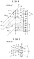
- Fig. 6 shows a first embodiment of the present invention.
- reference numeral 1 denotes the single plate type color liquid crystal panel means already mentioned
- 3 denotes the three-position means already mentioned
- 23 denotes the block including a light source and collimator means already mentioned
- 25 denotes a white ray
- 26 denotes macro prism type diffracting means including at a macroscopic level prisms and at a microscopic level a diffraction grating formed on the oblique side face of each prism.
- Reference numeral 27 denotes a diffraction grating
- ⁇ denotes the vertical angle of the macro prism
- P 0 denotes the pitch of the diffraction grating array
- P denotes the projection of P 0 as viewed from the emerging direction of the first order diffracted ray, that is, the projection of the pitch which is measured at right angles with the traveling direction of the light, and which is substantially equal to P 0 cos ⁇
- the h denotes the height of a unit step as a component part of the diffraction grating
- 24 and 24' denotes the side faces of the row of prisms, the respective side faces 24 and 24' being so arranged as to be substantially parallel with or at right angles with the incident white light 25.
- the Q denotes the arraignment pitch of the row of macro prisms as viewed from the direction of the incident light, in other words, the projection of the pitch in the direction at right angles with the light traveling direction.
- the 8, 8' and 8'' denotes G, R and B rays of the first order diffracted output rays, and ⁇ denotes the R-G separation angle.
- ⁇ 0 denotes the characteristic wavelength of this system
- n denotes the refractive index of the medium forming the macro prism type light diffracting means.
- the first order diffracted ray of wavelength ⁇ 0 passes at zero deflected angle through the light diffracting means. This is because the effective optical path difference at each unit step of the diffraction grating is a difference of (n-1)h between nh in the medium and h in the air and the difference is equal to wavelength ⁇ 0 according to equation (17).
- Fig. 6 exemplifies a case where ⁇ 0 is equated with ⁇ G .
- the ⁇ R , ⁇ B or any specific wavelength of the infrared or ultraviolet region can be selected for the ⁇ 0 in a range that the selected wavelength satisfies equation (21).
- Equation (18) expresses the relation between the R-B separation angle ⁇ and the projected pitch P of diffraction grating.
- the R-G separation angle 3° or larger ( ⁇ of 0.05 rad or more), which is aimed at in the present invention, it is required to set the projected pitch P at 1.6 ⁇ m or less according to equation (18).
- Inequality (19) is the condition for limiting the diffraction by the macro prism to less than 0.01 rad. By satisfying this condition, the light diverging angle can be prevented from increasing, so that a liquid crystal display with reduced color mixture between R, G and B and superior picture quality can be realized.
- the L is a positive integer of 1 or more or 3 or less.
- the value of L was 1.
- the L value of 4 or larger is not recommended. The reason is that if the L value is 4 or larger, the diffraction efficiency declines intolerably, though detailed description is omitted here. If the value of L is 1, 2 or 3, these values may be used in this embodiment. In such a case, the L-th order diffracted light is used.
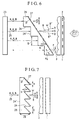
- the macro prism type light diffracting means 26 has a macro prism provided on the light input side thereof and a diffraction grating 27 formed on the light output side thereof, whereas in Fig. 7, both the macro prism and the diffraction grating 27 are provided on the light output side of the macro prism type diffraction grating means 26.
- the macro prism type light diffracting means 26 and the diffraction grating 27 may be manufactured separately and joined together later.
- Equation (23) shows the condition for setting the effective optical path difference (n - 1)h(x) of each step of the grating for G ray so that the L-th order diffracted G ray travels in the direction of the G pixel.
- the denominator, D 0 /n + D(x) - D 0 , of the last term of equation (23) is the effective optical path length from the diffraction grating to the pixel row of the liquid crystal panel, and the numerator x is the distance in the x direction measured from the center of the G pixel. The ratio between them is equal to the deflected angle ⁇ G of G ray.
- Equation (25) shows the condition for making the R-G separation angle equal to ⁇ . Inequality (19) has already been described.
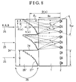
- the diverging angle of output from the liquid crystal panel in the third embodiment has a large value of 5 ⁇ as shown in Fig. 8.
- This vale is equal to the output diverging angle of 5 ⁇ in the prior art in Fig. 5 and corresponds to the total value of ⁇ and ⁇ 1.5 ⁇ in Fig. 4.
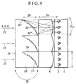
- a fourth embodiment for decreasing the output diverging angle to about 3 ⁇ is shown in Fig. 9.
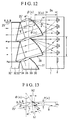
- Fig. 12 the parts designated as 1, 2, and 25 are the same as have been described, 32 denotes linear Fresnel lens means, 32' denotes the light input face of this Fresnel lens means, 32'' denotes a prism face formed on the light output face of the Fresnel lens means, 33 denotes light diffracting means having macro prisms combined with lenticular faces at its macroscopic level, and includes diffraction gratings at its microscopic level, 34 denotes a prism face formed on the light input face of the diffracting means, dotted lines 36 denote macro prisms combined with lenticular faces, 37 denotes diffraction gratings, and 38 denotes discontinuation faces of the macro prisms.
- Equation (33) by periodically modulating the effective unit optical path difference as a function of x, the G output rays can be directed toward the G pixels. This modulation can be achieved by keeping compatibility with the constraint condition equation (25') showing the definition of the R-G separation angle. Therefore, Items 3.3 and 3.4 in Fig. 1 already described can be satisfied at the same time. Equation (34) shows the condition to be satisfied by the prism faces 32'' and 34. Equation (35) is a condition for specifying the microscopic-level prism angle of the diffraction grating. To satisfy this condition is effective for increasing the diffraction efficiency close to 1.
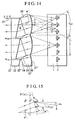
- Fig. 14 shows an eighth embodiment of the present invention, which belongs to Type II in Fig. 1 already mentioned.
- the parts designated by 1, 2, 25, 32, 32', 32'', 34, and 35 are the same as have been described above
- 33' denotes light diffracting means has a lenticular structure at its macroscopic level, and includes diffraction gratings at its microscopic level
- 36' denotes a dotted line indicating the macro lenticular shape
- 37' denotes diffraction gratings.
- Fig. 15 is a fragmentary view on an enlarged scale.
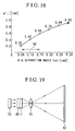
- Fig. 18 graphically depicts equation (37) and corresponds to a case where the material has a normal refractive index value of 1.5.
- ⁇ 1 ' to about 0.6 or less rad is required to practically realize the prism components. Therefore, the applicable range of the eighth and ninth embodiments is the range indicated by 50 in Fig. 8. This range fully covers the range shown in inequality (10) mentioned above.
Landscapes
- Physics & Mathematics (AREA)
- Engineering & Computer Science (AREA)
- Multimedia (AREA)
- Signal Processing (AREA)
- General Physics & Mathematics (AREA)
- Optics & Photonics (AREA)
- Liquid Crystal (AREA)
- Transforming Electric Information Into Light Information (AREA)
- Devices For Indicating Variable Information By Combining Individual Elements (AREA)
- Optical Elements Other Than Lenses (AREA)
- Projection Apparatus (AREA)
- Diffracting Gratings Or Hologram Optical Elements (AREA)
Applications Claiming Priority (3)
| Application Number | Priority Date | Filing Date | Title |
|---|---|---|---|
| JP95036/96 | 1996-04-17 | ||
| JP9503696 | 1996-04-17 | ||
| JP8095036A JPH09284684A (ja) | 1996-04-17 | 1996-04-17 | 単板式カラー液晶ディスプレイ装置 |
Publications (3)
| Publication Number | Publication Date |
|---|---|
| EP0802685A2 true EP0802685A2 (de) | 1997-10-22 |
| EP0802685A3 EP0802685A3 (de) | 1999-04-07 |
| EP0802685B1 EP0802685B1 (de) | 2004-09-08 |
Family
ID=14126863
Family Applications (1)
| Application Number | Title | Priority Date | Filing Date |
|---|---|---|---|
| EP97105927A Expired - Lifetime EP0802685B1 (de) | 1996-04-17 | 1997-04-10 | Farbanzeigevorrichtung mit einer Flüssigkristallplatte und Brechungsgitter |
Country Status (6)
| Country | Link |
|---|---|
| US (2) | US5801795A (de) |
| EP (1) | EP0802685B1 (de) |
| JP (1) | JPH09284684A (de) |
| KR (1) | KR100229515B1 (de) |
| CN (1) | CN1092898C (de) |
| DE (1) | DE69730553T2 (de) |
Cited By (3)
| Publication number | Priority date | Publication date | Assignee | Title |
|---|---|---|---|---|
| EP0965875A1 (de) * | 1998-06-16 | 1999-12-22 | Seiko Epson Corporation | Flüssigkristallvorrichtung sowie ein Projektionsanzeigegerät, welches eine solche Vorrichtung verwendet |
| EP1387205A1 (de) * | 2002-07-30 | 2004-02-04 | Samsung Electronics Co., Ltd. | Anzeigesystem hoher Auflösung mit einem optischen System mit beweglichen Pixeln |
| WO2007115664A1 (de) * | 2006-04-06 | 2007-10-18 | Oc Oerlikon Balzers Ag | Projektionsbeleuchtungssystem, in dem linsen mit diffraktiv optischen elementen verwendet werden |
Families Citing this family (50)
| Publication number | Priority date | Publication date | Assignee | Title |
|---|---|---|---|---|
| JPH10115871A (ja) * | 1996-10-14 | 1998-05-06 | Canon Inc | 画像投射装置 |
| EP0841821A3 (de) * | 1996-11-06 | 2000-01-12 | Canon Kabushiki Kaisha | Projektionsvorrichtung |
| US6104446A (en) * | 1996-12-18 | 2000-08-15 | Blankenbecler; Richard | Color separation optical plate for use with LCD panels |
| JP3647206B2 (ja) * | 1997-05-20 | 2005-05-11 | キヤノン株式会社 | 光学変調装置及びそれを用いた投影装置 |
| JPH11149061A (ja) * | 1997-09-12 | 1999-06-02 | Minolta Co Ltd | 光源装置および照明装置 |
| US6480333B1 (en) * | 1997-11-19 | 2002-11-12 | California Institute Of Technology | Diffractive optical elements on non-flat substrates using electron beam lithography |
| US6678023B1 (en) | 1997-12-17 | 2004-01-13 | Semiconductor Energy Laboratory Co., Ltd. | Liquid crystal projector |
| JP3779052B2 (ja) * | 1997-12-17 | 2006-05-24 | 株式会社半導体エネルギー研究所 | 液晶プロジェクタ |
| FI106323B (fi) | 1998-12-30 | 2001-01-15 | Nokia Mobile Phones Ltd | Taustavalaistuksen valonjohdin litteälle näytölle |
| JP2000329925A (ja) * | 1999-05-18 | 2000-11-30 | Sony Corp | 光発散角制限装置および方法並びに投写型画像表示装置 |
| US6351334B1 (en) * | 2000-10-10 | 2002-02-26 | Industrial Technology Research Institute | Reflective diffraction grating for use in display devices |
| JP2002122809A (ja) * | 2000-10-18 | 2002-04-26 | Canon Inc | 投射型表示装置 |
| US6600528B2 (en) | 2000-12-19 | 2003-07-29 | International Business Machines Corporation | Integrated prism sheet for improved viewing angle in direct view color filterless liquid crystal displays |
| KR100482318B1 (ko) * | 2001-05-23 | 2005-04-13 | 엘지전자 주식회사 | 후면 투사장치의 컬러 스크롤링 장치 |
| CN1313846C (zh) * | 2001-10-05 | 2007-05-02 | 松下电器产业株式会社 | 衍射光学元件及使用了该衍射光学元件的光学头 |
| EP1351073B1 (de) * | 2002-04-04 | 2009-12-16 | Canon Kabushiki Kaisha | Diffraktives optisches Element mit einer Vielzahl von Beugungsgittern und optisches System |
| US20040247010A1 (en) * | 2002-10-07 | 2004-12-09 | Makoto Okada | Antireflection diffraction grating |
| US6888691B2 (en) * | 2003-04-03 | 2005-05-03 | Thomson Licensing S. A. | Apparatus and method for isolating optics from thermal expansion |
| CN100426091C (zh) * | 2003-05-02 | 2008-10-15 | 鸿富锦精密工业(深圳)有限公司 | 背光模组及其导光板 |
| JP2005062692A (ja) * | 2003-08-19 | 2005-03-10 | Internatl Business Mach Corp <Ibm> | カラー表示装置、光学素子、およびカラー表示装置の製造方法 |
| CN100468151C (zh) * | 2004-03-11 | 2009-03-11 | 鸿富锦精密工业(深圳)有限公司 | 直下式背光模组 |
| US20060056028A1 (en) * | 2004-09-13 | 2006-03-16 | Wildnauer Kenneth R | Apodized diffraction grating with improved dynamic range |
| TWI255349B (en) * | 2005-02-02 | 2006-05-21 | Asia Optical Co Inc | Optical system of a projector display and a projector device equipped with this optical system |
| US7554623B2 (en) * | 2005-02-18 | 2009-06-30 | Infocus Corporation | Optical assembly to provide complementary illumination of subpixels of a light valve pixel |
| US7868847B2 (en) * | 2005-05-24 | 2011-01-11 | Mark W Miles | Immersive environments with multiple points of view |
| US7729052B2 (en) * | 2005-07-01 | 2010-06-01 | Cotton Christopher T | Non-planar optical diffraction grating having an arbitrary parallel groove profile |
| KR101217160B1 (ko) * | 2006-08-09 | 2012-12-31 | 엘지디스플레이 주식회사 | 마이크로 프리즘을 이용한 액정표시장치 |
| KR100993383B1 (ko) * | 2007-03-15 | 2010-11-09 | 제일모직주식회사 | 프리즘의 계곡부위에 형성된 광확산체를 포함하는 디퓨져프리즘 시트 및 이를 이용한 액정표시장치 |
| KR101243709B1 (ko) * | 2008-02-22 | 2013-03-13 | 주식회사 엘지화학 | 양면 돌출부를 갖는 편향 필름 및 이를 이용한 엣지형백라이트 유닛 |
| TWI354809B (en) | 2008-06-24 | 2011-12-21 | Ind Tech Res Inst | Composite optical dividing device |
| TWI391707B (zh) * | 2008-10-30 | 2013-04-01 | Ind Tech Res Inst | 複合式分光元件 |
| TWI424200B (zh) | 2008-12-31 | 2014-01-21 | Ind Tech Res Inst | 色彩分離光學元件以及所應用的影像裝置 |
| CN101799589B (zh) * | 2009-02-09 | 2013-05-08 | 财团法人工业技术研究院 | 色彩分离光学元件以及影像面板装置 |
| US8290318B2 (en) * | 2009-04-21 | 2012-10-16 | Svv Technology Innovations, Inc. | Light trapping optical cover |
| US20100309554A1 (en) * | 2009-06-03 | 2010-12-09 | Panasonic Corporation | Color separation microlens and color separation grating |
| GB2476799A (en) * | 2010-01-07 | 2011-07-13 | Sharp Kk | Reflective display, sensor and camera |
| US8902506B2 (en) | 2010-09-30 | 2014-12-02 | Panasonic Corporation | Laser speckle reduction element |
| US8740397B2 (en) * | 2011-01-18 | 2014-06-03 | Svv Technology Innovations, Inc. | Optical cover employing microstructured surfaces |
| US20130033752A1 (en) * | 2011-08-04 | 2013-02-07 | Chien-Yue Chen | Diffraction-type 3d display element and method for fabricating the same |
| JP2013044800A (ja) * | 2011-08-22 | 2013-03-04 | Sony Corp | 照明装置および表示装置 |
| WO2015016844A1 (en) * | 2013-07-30 | 2015-02-05 | Leia Inc. | Multibeam diffraction grating-based backlighting |
| KR20160067546A (ko) * | 2014-12-04 | 2016-06-14 | 한국전자통신연구원 | 지향성 백라이트 유닛 |
| CN106959518B (zh) * | 2016-01-08 | 2020-02-18 | 京东方科技集团股份有限公司 | 一种显示面板和显示装置 |
| CN106094331B (zh) * | 2016-06-03 | 2019-03-12 | 京东方科技集团股份有限公司 | 一种显示面板及显示装置 |
| CN106324898B (zh) * | 2016-10-28 | 2017-08-25 | 京东方科技集团股份有限公司 | 显示面板及显示装置 |
| JP7062366B2 (ja) * | 2017-03-03 | 2022-05-06 | 株式会社ジャパンディスプレイ | 表示装置、表示方法及び色分離素子 |
| CN107144904B (zh) * | 2017-05-25 | 2019-06-04 | 北京理工大学 | 一种消色差光栅、消色差方法及近眼显示系统 |
| CN111095128B (zh) * | 2017-09-08 | 2022-02-25 | 大日本印刷株式会社 | 光调制元件和信息记录介质 |
| DE102018212719A1 (de) * | 2018-07-31 | 2020-02-20 | Dr. Johannes Heidenhain Gesellschaft Mit Beschränkter Haftung | Optische Positionsmesseinrichtung |
| US12100440B2 (en) | 2022-02-08 | 2024-09-24 | Changxin Memory Technologies, Inc. | Sense amplifier circuit, method for operating same, and fabrication method for same |
Family Cites Families (15)
| Publication number | Priority date | Publication date | Assignee | Title |
|---|---|---|---|---|
| JPS60146590A (ja) * | 1984-01-10 | 1985-08-02 | Citizen Watch Co Ltd | 多色画像表示装置 |
| JPH0792566B2 (ja) * | 1986-06-12 | 1995-10-09 | キヤノン株式会社 | カラ−表示装置 |
| JPS63118125A (ja) * | 1986-11-06 | 1988-05-23 | Hitachi Ltd | 液晶表示装置 |
| US4798448A (en) * | 1988-02-16 | 1989-01-17 | General Electric Company | High efficiency illumination system for display devices |
| JPH0659318A (ja) * | 1991-07-19 | 1994-03-04 | Canon Inc | カメラ |
| WO1993011452A1 (en) * | 1991-11-25 | 1993-06-10 | Magnascreen Corporation | Microprojection display system with fiber-optic illuminator, and method of display and illumination |
| US5264880A (en) * | 1991-12-30 | 1993-11-23 | Xerox Corporation | Method and apparatus for projecting a color image |
| US5537171A (en) * | 1992-03-13 | 1996-07-16 | Hitachi, Ltd. | Liquid crystal projection display |
| GB2269697A (en) * | 1992-08-11 | 1994-02-16 | Sharp Kk | Display device |
| US5506701A (en) * | 1993-01-28 | 1996-04-09 | Dai Nippon Printing Co., Ltd. | Hologram color filter, liquid crystal display device using the same, and fabrication process of hologram color filter |
| JP2643755B2 (ja) * | 1993-02-26 | 1997-08-20 | 株式会社日立製作所 | 液晶ディスプレイ |
| FR2707447B1 (fr) * | 1993-07-09 | 1995-09-01 | Thomson Csf | Dispositif de visualisation couleurs. |
| US5682265A (en) * | 1994-02-18 | 1997-10-28 | Massachusetts Institute Of Technology | Diffractive microstructures for color separation and fusing |
| EP0692730A3 (de) * | 1994-07-12 | 1996-03-20 | Dainippon Printing Co Ltd | Flüssigkristall-Anzeigevorrichtung und Flüssigkristall-Projektionsanzeigevorrichtung unter Verwendung eines holographischen Farbfilters |
| US5781257A (en) * | 1995-01-30 | 1998-07-14 | Lockheed Martin Missiles & Space Co | Flat panel display |
-
1996
- 1996-04-17 JP JP8095036A patent/JPH09284684A/ja active Pending
-
1997
- 1997-04-10 US US08/838,831 patent/US5801795A/en not_active Expired - Fee Related
- 1997-04-10 EP EP97105927A patent/EP0802685B1/de not_active Expired - Lifetime
- 1997-04-10 DE DE69730553T patent/DE69730553T2/de not_active Expired - Fee Related
- 1997-04-16 KR KR1019970013968A patent/KR100229515B1/ko not_active Expired - Fee Related
- 1997-04-17 CN CN97113205A patent/CN1092898C/zh not_active Expired - Fee Related
-
1998
- 1998-07-22 US US09/120,324 patent/US6064452A/en not_active Expired - Fee Related
Cited By (5)
| Publication number | Priority date | Publication date | Assignee | Title |
|---|---|---|---|---|
| EP0965875A1 (de) * | 1998-06-16 | 1999-12-22 | Seiko Epson Corporation | Flüssigkristallvorrichtung sowie ein Projektionsanzeigegerät, welches eine solche Vorrichtung verwendet |
| US6195143B1 (en) | 1998-06-16 | 2001-02-27 | Seiko Epson Corporation | Liquid crystal panel structure with micro-lens array and projector using the micro-lens array |
| EP1387205A1 (de) * | 2002-07-30 | 2004-02-04 | Samsung Electronics Co., Ltd. | Anzeigesystem hoher Auflösung mit einem optischen System mit beweglichen Pixeln |
| US6971748B2 (en) | 2002-07-30 | 2005-12-06 | Samsung Electronics Co., Ltd. | High-resolution display including pixel moving optical system |
| WO2007115664A1 (de) * | 2006-04-06 | 2007-10-18 | Oc Oerlikon Balzers Ag | Projektionsbeleuchtungssystem, in dem linsen mit diffraktiv optischen elementen verwendet werden |
Also Published As
| Publication number | Publication date |
|---|---|
| US5801795A (en) | 1998-09-01 |
| EP0802685B1 (de) | 2004-09-08 |
| CN1092898C (zh) | 2002-10-16 |
| DE69730553T2 (de) | 2005-01-27 |
| CN1175164A (zh) | 1998-03-04 |
| EP0802685A3 (de) | 1999-04-07 |
| KR100229515B1 (ko) | 1999-11-15 |
| US6064452A (en) | 2000-05-16 |
| JPH09284684A (ja) | 1997-10-31 |
| DE69730553D1 (de) | 2004-10-14 |
Similar Documents
| Publication | Publication Date | Title |
|---|---|---|
| US5801795A (en) | Single plate color liquid crystal display apparatus | |
| US6343862B1 (en) | Projecting image display device | |
| US5594563A (en) | High resolution subtractive color projection system | |
| US4687301A (en) | Full-color projector system with a tricolor-separating prism | |
| KR100359594B1 (ko) | 광학적 투사 장치, 투과형 스크린, 및 투사형 화상 표시장치 | |
| EP0717865B1 (de) | Flüssigkristall-projektionsanzeigesysteme | |
| CN1322359C (zh) | 图象显示器件和图象显示设备 | |
| US8305527B2 (en) | Color separation system | |
| EP1780560B1 (de) | Räumlicher Lichtmodulator und Projektor | |
| US7667898B2 (en) | Zoom lens and projector | |
| EP0802443A1 (de) | Flüssigkristallanzeigevorrichtung | |
| US6481852B2 (en) | Projector apparatus comprising a light composing optical system vertically stacked with respect to a light separation optical system | |
| US20020196413A1 (en) | Optical systems for liquid crystal display projectors | |
| JP2007087647A (ja) | 導光板、バックライトおよび液晶表示装置 | |
| US6141124A (en) | Color filter and color picture display device using the same | |
| EP0762781A2 (de) | Optische Vorrichtung, Projektionsanzeigevorrichtung und optisches Kompensationsverfahren | |
| KR20050025904A (ko) | 화상투사장치 | |
| JP2005070632A (ja) | 空間光変調装置及びプロジェクタ | |
| JP3744233B2 (ja) | 偏光分離器および投射型画像表示装置 | |
| JP2002006298A (ja) | 投射型カラー画像表示装置 | |
| JP3200335B2 (ja) | 光学変調装置及びそれを用いたカラー画像表示装置 | |
| JPH09329788A (ja) | ホログラムカラーフィルターシステム | |
| US20050105056A1 (en) | Compact projection display device | |
| JP3200334B2 (ja) | 光学変調装置及びそれを用いたカラー画像表示装置 | |
| JPH11316357A (ja) | 投射型表示装置 |
Legal Events
| Date | Code | Title | Description |
|---|---|---|---|
| PUAI | Public reference made under article 153(3) epc to a published international application that has entered the european phase |
Free format text: ORIGINAL CODE: 0009012 |
|
| 17P | Request for examination filed |
Effective date: 19970410 |
|
| AK | Designated contracting states |
Kind code of ref document: A2 Designated state(s): DE FR GB |
|
| PUAL | Search report despatched |
Free format text: ORIGINAL CODE: 0009013 |
|
| AK | Designated contracting states |
Kind code of ref document: A3 Designated state(s): DE FR GB |
|
| GRAP | Despatch of communication of intention to grant a patent |
Free format text: ORIGINAL CODE: EPIDOSNIGR1 |
|
| RTI1 | Title (correction) |
Free format text: SINGLE PLATE LIQUID CRYSTAL COLOUR DISPLAY APPARATUS EMPLOYING A DIFFRACTION GRATING |
|
| GRAS | Grant fee paid |
Free format text: ORIGINAL CODE: EPIDOSNIGR3 |
|
| GRAA | (expected) grant |
Free format text: ORIGINAL CODE: 0009210 |
|
| AK | Designated contracting states |
Kind code of ref document: B1 Designated state(s): DE FR GB |
|
| REG | Reference to a national code |
Ref country code: GB Ref legal event code: FG4D |
|
| REF | Corresponds to: |
Ref document number: 69730553 Country of ref document: DE Date of ref document: 20041014 Kind code of ref document: P |
|
| PGFP | Annual fee paid to national office [announced via postgrant information from national office to epo] |
Ref country code: FR Payment date: 20050218 Year of fee payment: 9 |
|
| PG25 | Lapsed in a contracting state [announced via postgrant information from national office to epo] |
Ref country code: GB Free format text: LAPSE BECAUSE OF NON-PAYMENT OF DUE FEES Effective date: 20050410 |
|
| PGFP | Annual fee paid to national office [announced via postgrant information from national office to epo] |
Ref country code: DE Payment date: 20050421 Year of fee payment: 9 |
|
| PLBE | No opposition filed within time limit |
Free format text: ORIGINAL CODE: 0009261 |
|
| STAA | Information on the status of an ep patent application or granted ep patent |
Free format text: STATUS: NO OPPOSITION FILED WITHIN TIME LIMIT |
|
| ET | Fr: translation filed | ||
| 26N | No opposition filed |
Effective date: 20050609 |
|
| GBPC | Gb: european patent ceased through non-payment of renewal fee |
Effective date: 20050410 |
|
| PG25 | Lapsed in a contracting state [announced via postgrant information from national office to epo] |
Ref country code: DE Free format text: LAPSE BECAUSE OF NON-PAYMENT OF DUE FEES Effective date: 20061101 |
|
| REG | Reference to a national code |
Ref country code: FR Ref legal event code: ST Effective date: 20061230 |
|
| PG25 | Lapsed in a contracting state [announced via postgrant information from national office to epo] |
Ref country code: FR Free format text: LAPSE BECAUSE OF NON-PAYMENT OF DUE FEES Effective date: 20060502 |