EP0802475B1 - Vielseitige Verbindung von tragbaren Vorrichtungen mit einem Hauptrechnersystem - Google Patents
Vielseitige Verbindung von tragbaren Vorrichtungen mit einem Hauptrechnersystem Download PDFInfo
- Publication number
- EP0802475B1 EP0802475B1 EP97302230A EP97302230A EP0802475B1 EP 0802475 B1 EP0802475 B1 EP 0802475B1 EP 97302230 A EP97302230 A EP 97302230A EP 97302230 A EP97302230 A EP 97302230A EP 0802475 B1 EP0802475 B1 EP 0802475B1
- Authority
- EP
- European Patent Office
- Prior art keywords
- media clip
- handheld device
- connector
- electrical connector
- clip pad
- Prior art date
- Legal status (The legal status is an assumption and is not a legal conclusion. Google has not performed a legal analysis and makes no representation as to the accuracy of the status listed.)
- Expired - Lifetime
Links
Images


Classifications
-
- G—PHYSICS
- G06—COMPUTING OR CALCULATING; COUNTING
- G06F—ELECTRIC DIGITAL DATA PROCESSING
- G06F1/00—Details not covered by groups G06F3/00 - G06F13/00 and G06F21/00
- G06F1/16—Constructional details or arrangements
- G06F1/1601—Constructional details related to the housing of computer displays, e.g. of CRT monitors, of flat displays
-
- G—PHYSICS
- G06—COMPUTING OR CALCULATING; COUNTING
- G06F—ELECTRIC DIGITAL DATA PROCESSING
- G06F1/00—Details not covered by groups G06F3/00 - G06F13/00 and G06F21/00
- G06F1/16—Constructional details or arrangements
- G06F1/1613—Constructional details or arrangements for portable computers
- G06F1/1632—External expansion units, e.g. docking stations
Definitions
- the present invention concerns computing devices and pertains particularly to the versatile attachment of handheld devices to a host computing system such as a portable computer.
- PIM personal information management
- Portable computers are often carried in a briefcase or bag. The display and keyboard are hidden when the computer is being carried. Users do not want to wait for the personal computer to boot up.
- portable computers are relatively bulky and people do not want to carry a portable computer with them wherever they go. In the opinion of many, even the very smallest notebooks are too bulky to carry everywhere. They do not fit in a shirt pocket or a small purse. Additionally, portable computers are generally not equipped to capture "casual" information such as scribbles, voice memos and snapshots.
- PDAs personal digital assistants
- personal organizers are relatively small and are generally designed to provide some ability to capture casual information. However, because they do not have a full-sized keyboard or display, they are not significantly limited for input/output of significant amounts of information. Additionally, PDAs and personal organizers have generally been poorly integrated with personal computers and desktop computers in such a way that information may be simply and naturally shared.
- the versatility of a host computer is expanded by placing a hinged connector on an outside of a case of the host computer.
- the host computer is, for example, a portable computer such as a notebook computer or a laptop computer.
- the hinged connector includes an electrical connector to which a handheld device is connected and disconnected.
- a hinge connects the hinged connector to the case. The hinge allows the handheld device, when connected to the electrical connector, to rotate position with respect to the case.
- the handheld device can perform any of a variety of tasks.
- the handheld device is a media clip pad which includes a touch-sensitive display.
- the media clip pad additionally can include a digital camera.
- the digital camera includes a camera eye which is rotatable 270 degrees.
- the hinged connector includes, for example, a speaker system.
- a back of the speaker is expandable to allow for the increase in air volume resulting in a richer sound quality.
- the media clip pad or other handheld device, additionally can include an expansion port. This allows an additional device, such as a digital camera, to be separately attachable to the media clip pad.
- handheld devices such as a cellular phone or a pager, can be directly connectable to the hinged connector or to the expansion port of the media clip pad.
- the electrical connector is compatible with a personal computer memory card internal association (PCMCIA) card electrical interface.
- PCMCIA personal computer memory card internal association
- the electrical connector is compatible with a PCI bus interface, a SCSI bus interface, or some other standard or non-standard electrical interface.
- the handheld device includes, for example, an infrared (IR) transceiver. This is advantageous, for example, for tasks such as presentation control.
- IR infrared
- the IR transmitter is also useful for "beaming" information to and from other IR devices using, for example, an Infrared Data Association (IrDA) standard protocol.
- IrDA Infrared Data Association
- the present invention greatly increases the versatility of a portable computer.
- the invention allows separately operable handheld devices to be conveniently part of a portable computer or to be separate versatile stand-alone units.
- Figure 1 shows a media clip pad attached to a personal computer in accordance with a preferred embodiment of the present invention.
- Figure 2 shows use of the media clip pad in a first position when the portable computer shown in Figure 1 is opened in accordance with a preferred embodiment of the present invention.
- Figure 3 shows use of the media clip pad in a second position when the portable computer shown in Figure 1 is opened in accordance with a preferred embodiment of the present invention.
- Figure 4 shows use of a media clip pad in a desktop holder in accordance with a preferred embodiment of the present invention.
- Figure 5 shows use of a media clip pad placed on a monitor in accordance with a preferred embodiment of the present invention.
- Figure 6 shows details of how the media clip pad is attached to a personal computer in accordance with a preferred embodiment of the present invention.
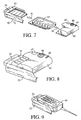
- Figure 7 shows details of how a digital camera is attached to the media clip pad shown in Figure 6 in accordance with a preferred embodiment of the present invention.
- Figure 8 shows how the digital camera shown in Figure 7 is directly attachable to a hinged connector on a personal computer in accordance with a preferred embodiment of the present invention.
- Figure 9 shows how a cellular phone is directly attachable to a personal computer in accordance with a preferred embodiment of the present invention.
- Figure 10 illustrates use of the digital camera and the media clip pad shown in Figure 7 separately from a portable computer in accordance with a preferred embodiment of the present invention.
- Figure 11 shows the hinge within a media clip pad holder on a personal computer in accordance with a preferred embodiment of the present invention.
- Figure 12 shows a electrical connector within a media clip pad holder on a personal computer, in accordance with a preferred embodiment of the present invention.
- Figure 13 shows a electrical connector within a media clip pad in accordance with a preferred embodiment of the present invention.
- Figure 14 shows the arrangement of circuitry within a media clip pad in accordance with a preferred embodiment of the present invention.
- Figure 15 shows a media clip pad with expandable speakers and an infrared (IR) transceiver in accordance with a preferred embodiment of the present invention.
- IR infrared
- Figure 16 shows a media clip attached to a portable computer connected to a docking station in accordance with a preferred embodiment of the present invention.
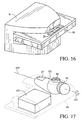
- Figure 17 shows additional detail of the digital camera shown in Figure 8 in accordance with a preferred embodiment of the present invention.
- Figure 1 shows a media clip pad 11 connected to a portable computer 10.
- Media clip pad 11 can be attached to or detached from portable computer 10 and/or a desktop computer.
- Media clip pad 11 includes microphone/speaker units 14, a digital camera 13 and a display/write pad 17.
- display/write pad 17 faces outward, as shown in Figure 1.
- portable computer 10 is in use (i.e., the case of portable computer 10 is open and a user is utilizing the keyboard and main display), media clip pad 11 may be rotated to a position visible and accessible to the user of portable computer 10.
- Display/write pad 17 provides a "spontaneous use" display for portable computer 10 which simplifies taking along bits of personal information such as appointments, phone number, notes and miscellaneous data files. Because display/write pad 17 includes a write pad feature, scribbled notes may be recorded. Additionally, through microphone/speaker units 14, voice memos may be recorded. Other spontaneous tasks include controlling portable computer 10 without opening the case. For example, in the preferred embodiment it is possible to control a CD drive of portable computer 10 without utilizing the main display of portable computer 10.
- digital camera 13 functions as a digital "still picture" camera when media clip pad 11 is detached from personal computer 10.
- media clip pad 11 utilizes the additional resources available to record full motion video.
- media clip pad 11 is connected to portable computer 10 by way of a hinge assembly.
- the hinge assembly allows rotation of the position of media clip 11 with respect to the top of portable computer 10.
- portable computer is opened and media clip pad 11 has been rotated to be perpendicular to the surface on which portable computer 10 rests.
- display 17 is viewable to a person positioned behind portable computer 10.
- microphone/speaker units 14 can record or play audio for a guest or audience.
- Digital camera 13 can be used for desktop video conferencing, video capture and/or the capture of still images.
- portable computer 10 includes a main display 16.
- portable computer is opened and media clip pad 11 has been rotated to face an operator of portable computer 10. In this position, display 17 is viewable to a user of portable computer 10.
- a modular portion 12 of media clip pad 11 is removable.
- Modular portion 12 includes a digital camera 13 and display/write pad 17.
- microphone/speaker units 14 can record or play audio for the user of portable computer 10.
- digital camera 13 can be used for desktop video conferencing, video capture and/or the capture of still images.
- FIG 4 shows a media clip pad 21 in which speakers 24, a digital camera 23 and a display 27 are all integrated in a single module.
- Media clip pad 27 can be mounted on a stand 25 which is connected through a cable 20 to a computing system.
- stand 25 may be integrated as part of a monitor 29, as shown in Figure 5.
- stand 25 may be placed on monitor 29. This is particularly useful, for example, when a docking system is used to connect a personal computer to monitor 29 and a keyboard 28.
- media clip pad 21 can remain connected to a portable computer and available for use by a user even when the portable computer is docked, provided that docking system does not cover the portion of the portable computer to which the docking system is attached.
- FIG. 16 This is illustrated by Figure 16 where media clip pad 21 is shown attached to a portable computer 90 and usable while portable computer 91 is connected to a docking station 91.
- FIG. 6 shows an implementation of a hinged connector 33 integrated as part of a portable computer 31.
- a media clip pad 32 slides right to left into hinged connector 33. Additional devices may be connected to media clip pad 32, however, in Figure 6, a protective filler cap 35 is placed to protect an expansion port of media clip pad 32.
- An eject button 34 of hinged connector 33 is used to release media clip pad 32 from hinged connector 33 pushing left to right. Eject button pushes equally on the corners of media clip pad 32, overcoming the friction of connection pins within the electrical connector within hinged connector 33.
- Media clip pad 32 includes a display/write pad 37 and touchpad buttons 36. Touchpad buttons 36 function as softkeys for user input.
- Figure 7 shows the insertion along a direction of media clip pad 32 into hinged connector 33.
- hinged connector 33 can rotate in directions 40 with respect to portable computer 31.
- a digital camera 46 can be inserted into the expansion port of media clip pad 32 along a direction 42.
- Digital camera 46 includes a camera eye 48, a flash assembly 47, and a thumb wheel 49.
- Camera eye 48 and flash assembly 47 are rotatable 270 degrees. This allows proper orientation of digital pictures/video from digital camera 46 both when media clip pad 32 is rotated to face a user using portable computer 31 and when media clip pad 32 is rotate to face a user or small audience behind portable computer 31.
- flash assembly 47 rotates along with camera eye 48, keeping flash unit 47 always pointed in the direction of camera eye 48.
- Thumb wheel 49 is used to rotate camera eye 48 and flash assembly 47.
- a portion of the 270 degree range allows camera eye 48 to be rotated inward (hidden) for protection when not in use.
- hinged connector 33 is identical to the electrical connector of the expansion port of media clip pad 32.
- digital camera 46 can be directly attached to hinged connector 33.
- FIG 17 shows additional detail of digital camera 46.
- flash unit 47 and camera eye 48 are mounted on a single unit 102.
- Thumb wheel 49 rotates unit 102 around an axis 104 as represented by arrow 103.
- Digital camera 46 includes a standard lithium camera battery 101 along with other circuitry.
- Figure 9 shows a cellular phone 43 attached to hinged connector 33.
- other devices for example a two-way pager card or IBM ChipCard device can be attached.
- digital camera 46 can remain attached to media clip pad 32 even when media clip pad 32 is separated from hinged connector 33.
- the display on the media clip pad 32 functions as a viewfinder for digital camera 46.
- any device with an appropriate connector can be attached to media clip pad 32.
- FIG 11 shows additional physical implementation detail of hinged connector 33.
- Hinged connector 33 is connected to portable computer 31 via a hinge 56.
- a hook 55 is used to keep hinged connector 33 flat against portable computer 31 when hinged connector 33 is in he stowed position.
- a button 54 is depressed in order to allow adjustment of the position of hinged connector 33 relative to portable computer 31. Friction at the assembly of hinge 56 allows hinged connector 33 to remain relatively stable in a position selected by a user. Electrical connection of a device attached to hinged connector 33 and portable computer 31 is achieved through a connector cable 52, placed through the hinge assembly of hinge 56.
- FIG 12 shows additional electrical implementation detail of hinged connector 33.
- Hinged connector 33 includes an electrical connector 51.
- electrical connector 51 is compatible with a personal computer memory card internal association (PCMCIA) card electrical interface.
- PCMCIA personal computer memory card internal association
- Connector cable 52 is shown in Figure 12 to be a mylar (or mylar-like) sheet with trace lines.
- Connector 52 is hidden with either a glue-in plate or is molded directly into hinged connector 33.
- electrical connector 51 is compatible with a PCI bus interface, a SCSI bus interface, or some other standard or non-standard electrical interface.
- Figure 13 shows additional electrical implementation detail of media clip pad 32.
- Media clip pad 32 includes a female electrical connector 61 and a male electrical connector 62.
- both electrical connector 61 and electrical connector 62 are compatible with a PCMCIA card electrical interface.
- electrical connectors 61 and 62 are compatible with a PCI bus interface, a SCSI bus interface, or some other standard or non-standard electrical interface.
- Electrical connector 61 is used to connect media clip pad 32 to hinged connector 33.
- Electrical connector 62 is used as the expansion port of media clip pad 32.
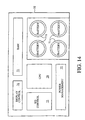
- FIG 14 shows a simplified block diagram of the layout of circuitry within media clip pad 32.
- Media clip pad 32 includes a display controller 74, random access memory (RAM) 73, an input/output (I/O) controller 75, power management circuitry 72 and a central processing unit (CPU) 76.
- display controller 74 random access memory
- I/O input/output
- CPU central processing unit
- media clip pad 32 uses batteries 71.
- FIG. 15 shows a media clip pad 80.
- speakers 85 expand when media clip pad 80 is tilted up. Speakers 85 expand to increase air volume for a richer sound quality.
- Removable portion 82 of media clip pad 80 includes a liquid crystal diode (LCD) display and a infrared transceiver 84.
- IR transceiver 84 is used as an remote control for simple manipulation of the portable computer from short range or to exchange information with other infrared devices. This is advantageous, for example, for tasks such as presentation control.
Landscapes
- Engineering & Computer Science (AREA)
- Theoretical Computer Science (AREA)
- General Engineering & Computer Science (AREA)
- Computer Hardware Design (AREA)
- Human Computer Interaction (AREA)
- Physics & Mathematics (AREA)
- General Physics & Mathematics (AREA)
- Telephone Set Structure (AREA)
- Calculators And Similar Devices (AREA)
Claims (10)
- Ein Rechensystem, das folgende Merkmale aufweist:ein Gehäuse;eine primäre Anzeige (16), die einem Anwender zur Verfügung steht, wenn das Gehäuse geöffnet ist; undeinen schwenkbar gelagerten Verbinder (33) an einer Außenseite des Gehäuses, wobei der schwenkbar gelagerte Verbinder (33) folgende Merkmale umfaßt:einen elektrischen Verbinder (51), mit dem eine tragbare Vorrichtung (32, 45, 46) verbunden und von dem dieselbe getrennt werden kann, wobei die tragbare Vorrichtung (32, 45, 46) eine separat betreibbare, alleinstehende Einheit ist, undein Scharnier (56), das den schwenkbar gelagerten Verbinder (33) mit dem Gehäuse verbindet, wobei das Scharnier (56) der tragbaren Vorrichtung (32, 45, 46) ermöglicht, wenn sie mit dem elektrischen Verbinder (51) verbunden ist, die Stellung im Hinblick auf das Gehäuse zu drehen.
- Rechensystem gemäß Anspruch 1, bei dem die tragbare Vorrichtung (32, 45, 46) eine Notizvorrichtung (32) ist, das eine berührungssensitive Anzeige (37) umfaßt.
- Ein Rechensystem gemäß Anspruch 2, bei dem die tragbare Vorrichtung (32, 45, 46) zusätzlich eine digitale Kamera (46) umfaßt.
- Ein Rechensystem gemäß Anspruch 3, bei dem die Notizvorrichtung (32) zusätzlich einen Erweiterungsport (42) umfaßt.
- Ein Rechensystem gemäß Anspruch 1, bei dem der elektrische Verbinder (51) mit einer elektrischen PCMCIA-Kartenschnittstelle (PCMCIA = personal Computer memory card internal association = interner Verband für Personal-Computer-Speicherkarten) kompatibel ist.
- Ein Verfahren zum Erweitern der Benutzervielseitigkeit eines Hostcomputers (31), das den nachstehenden Schritt aufweist:(a) Plazieren eines schwenkbar gelagerten Verbinders (33) an einer Außenseite eines Gehäuses des Hostcomputers (31), wobei die folgenden Teilschritte umfaßt sind:(a.1) Bereitstellen eines elektrischen Verbinders (51), mit dem eine tragbare Vorrichtung (32, 45, 46) verbunden und von dem dieselbe gelöst werden kann, wobei die tragbare Vorrichtung (32, 45, 46) eine separat betreibbare, alleinstehende Einheit ist; und(a.2) Bereitstellen eines Scharniers (56), das den schwenkbar gelagerten Verbinder (33) mit dem Gehäuse verbindet, wobei das Scharnier (56) der tragbaren Vorrichtung (32, 45, 46) ermöglicht, wenn sie mit dem elektrischen Verbinder (51) verbunden ist, die Stellung im Hinblick auf das Gehäuse zu drehen.
- Ein Verfahren gemäß Anspruch 6, bei dem im Teilschritt (a.1) die tragbare Vorrichtung (32, 45, 46) eine Notizvorrichtung (32) ist, die eine berührungssensitive Anzeige (37) umfaßt.
- Ein Verfahren gemäß Anspruch 7, bei dem in Teilschritt (a.1) die tragbare Vorrichtung (32, 45, 46) zusätzlich eine digitale Kamera (46) umfaßt.
- Ein Verfahren gemäß Anspruch 6, bei dem der Schritt(a) zusätzlich den folgenden Schritt umfaßt:(a.3) Verbinden eines Zellulartelefons (45) mit dem elektrischen Verbinder (51).
- Ein Verfahren gemäß Anspruch 6, bei dem der Schritt(a) zusätzlich den folgenden Schritt umfaßt:(a.3) Verbinden einer Rufvorrichtung mit dem elektrischen Verbinder (51).
Applications Claiming Priority (2)
| Application Number | Priority Date | Filing Date | Title |
|---|---|---|---|
| US08/632,211 US5768163A (en) | 1996-04-15 | 1996-04-15 | Versatile attachment of handheld devices to a host computing system |
| US632211 | 1996-04-15 |
Publications (2)
| Publication Number | Publication Date |
|---|---|
| EP0802475A1 EP0802475A1 (de) | 1997-10-22 |
| EP0802475B1 true EP0802475B1 (de) | 2002-02-20 |
Family
ID=24534553
Family Applications (1)
| Application Number | Title | Priority Date | Filing Date |
|---|---|---|---|
| EP97302230A Expired - Lifetime EP0802475B1 (de) | 1996-04-15 | 1997-04-01 | Vielseitige Verbindung von tragbaren Vorrichtungen mit einem Hauptrechnersystem |
Country Status (4)
| Country | Link |
|---|---|
| US (1) | US5768163A (de) |
| EP (1) | EP0802475B1 (de) |
| JP (1) | JPH1074119A (de) |
| DE (1) | DE69710511T2 (de) |
Families Citing this family (113)
| Publication number | Priority date | Publication date | Assignee | Title |
|---|---|---|---|---|
| US6141052A (en) * | 1996-04-15 | 2000-10-31 | Sony Corporation | Portable personal computer and electronic camera |
| JPH1056586A (ja) * | 1996-08-13 | 1998-02-24 | Nikon Corp | 撮像装置 |
| US5880783A (en) * | 1996-11-19 | 1999-03-09 | Ma; Hsi-Kuang | Digital camera for a computer |
| KR100278358B1 (ko) * | 1997-06-03 | 2001-01-15 | 윤종용 | 카메라 장착장치를 갖는 휴대용 컴퓨터 |
| US6925188B1 (en) | 1997-06-20 | 2005-08-02 | Hewlett-Packard Development Company, L.P. | Ported speaker enclosure of a portable computer |
| US6633647B1 (en) * | 1997-06-30 | 2003-10-14 | Hewlett-Packard Development Company, L.P. | Method of custom designing directional responses for a microphone of a portable computer |
| US6081422A (en) * | 1997-08-19 | 2000-06-27 | Compaq Computer Corporation | Universal mount for computer peripheral device |
| US6266236B1 (en) | 1997-08-27 | 2001-07-24 | Vadem | Apparatus and method for connecting and articulating display in a portable computer having multiple display orientations |
| US5948086A (en) * | 1997-10-03 | 1999-09-07 | Inventec Corporation | Electronic still camera adapted for use in the battery receiving chamber of a portable computer |
| US6040978A (en) * | 1997-11-26 | 2000-03-21 | Gateway 2000, Inc. | Portable computer having folding speakers |
| US5982613A (en) * | 1997-12-18 | 1999-11-09 | Daniel I. Sternglass | Open-surfaced receptacle in an electronic product for a removable electronic module |
| TW352206U (en) * | 1997-12-30 | 1999-02-01 | First Int Computer Inc | Structure for hidden type image picking apparatus of notebook computer |
| US6340235B1 (en) * | 1998-01-12 | 2002-01-22 | Jimmy H. Bryan | Adaptable electric accessory system for containers, receptacles, and the like |
| US20040090773A1 (en) * | 1998-01-12 | 2004-05-13 | Bryan Jimmy H. | Adaptable electric accessory system for containers, receptacles, and the like |
| US6462781B1 (en) * | 1998-04-07 | 2002-10-08 | Pitcos Technologies, Inc. | Foldable teleconferencing camera |
| US6657654B2 (en) * | 1998-04-29 | 2003-12-02 | International Business Machines Corporation | Camera for use with personal digital assistants with high speed communication link |
| JP4099736B2 (ja) | 1998-06-30 | 2008-06-11 | ソニー株式会社 | 情報処理装置 |
| JP2000020163A (ja) * | 1998-06-30 | 2000-01-21 | Sony Corp | 情報処理装置 |
| JP4182603B2 (ja) | 1998-10-07 | 2008-11-19 | ソニー株式会社 | 符号化装置および符号化方法、復号装置および復号方法、記録媒体、並びにデータ処理装置 |
| EP0975132A1 (de) * | 1998-07-20 | 2000-01-26 | Alcatel | KommuniKationssystem, das aus mindestens einem mobilen Telephon und mindestens einer Kamera besteht |
| US6097593A (en) | 1998-08-14 | 2000-08-01 | Digital Equipment Corporation | Semi-mobile desktop personal computer |
| US6812958B1 (en) * | 1998-09-10 | 2004-11-02 | Intel Corporation | Storable digital camera associated with a computer system |
| US6028764A (en) * | 1998-09-28 | 2000-02-22 | Intel Corporation | Portable computer with separable screen |
| JP2000137544A (ja) * | 1998-11-02 | 2000-05-16 | Fuji Photo Film Co Ltd | ノートブック型パーソナルコンピュータ |
| US6304435B1 (en) * | 1998-11-12 | 2001-10-16 | Acer Incorporated | Laptop computer with flat panel speakers |
| US6496361B2 (en) * | 1998-11-16 | 2002-12-17 | Acer Incorporated | Embedded CMOS camera in a laptop computer |
| US6343006B1 (en) * | 1998-11-20 | 2002-01-29 | Jerry Moscovitch | Computer display screen system and adjustable screen mount, and swinging screens therefor |
| WO2000039493A1 (en) * | 1998-12-23 | 2000-07-06 | Jerry Moscovitch | Computer display screen system and adjustable screen mount, and swinging screens therefor |
| US6078497A (en) * | 1999-01-29 | 2000-06-20 | Hewlett-Packard Company | Portable electronic device having an enhanced speaker system |
| DE19910648A1 (de) * | 1999-03-10 | 2000-09-21 | Siemens Ag | Videohandy |
| US6144552A (en) * | 1999-04-26 | 2000-11-07 | Emc Corporation | Handheld computer system |
| US6191942B1 (en) * | 1999-06-22 | 2001-02-20 | Compal Electronics, Inc. | Portable computer |
| US7047038B1 (en) * | 1999-07-14 | 2006-05-16 | Avaya Technology Corp. | Computer and mobile communication system |
| JP2001051749A (ja) * | 1999-07-30 | 2001-02-23 | Internatl Business Mach Corp <Ibm> | オプション・ユニットの装着可能なコンピュータ |
| AU6462600A (en) | 1999-08-23 | 2001-03-19 | Mass Engineered Design | Universal quick connector apparatus for an lcd monitor |
| US6600657B1 (en) | 1999-10-12 | 2003-07-29 | Mitsubishi Electric Research Laboratories, Inc. | Accessory adapted for digital personal assistant |
| EP1096422A1 (de) * | 1999-10-25 | 2001-05-02 | Swatch Ag | Schnittstelle zwischen einem Kontaktenleser und einer kontaktlosen Vorrichtung |
| JP2001142563A (ja) | 1999-11-09 | 2001-05-25 | Internatl Business Mach Corp <Ibm> | 機能補完型携帯情報装置 |
| US10061369B2 (en) * | 1999-11-29 | 2018-08-28 | Intel Corporation | Automatically enabling information to be displayed after a processor-based system is turned off |
| US6912006B2 (en) * | 2001-04-16 | 2005-06-28 | Sony Corporation | Exposure controller for camera attached to electronic equipment |
| US6481681B1 (en) * | 2000-08-30 | 2002-11-19 | 3Com Corporation | Clip apparatus for a laptop computer |
| JP2002158944A (ja) * | 2000-09-07 | 2002-05-31 | Canon Inc | 画像表示システム、画像表示装置及び画像表示装置の周辺機器 |
| US6717801B1 (en) | 2000-09-29 | 2004-04-06 | Hewlett-Packard Development Company, L.P. | Standardized RF module insert for a portable electronic processing device |
| DE60140494D1 (de) * | 2000-10-13 | 2009-12-24 | Lg Electronics Inc | Vorrichtung zur automatischen Winkeleinstellung einer Bildvorrichtung für ein Informationsverarbeitungsgerät |
| DE10053209A1 (de) * | 2000-10-26 | 2002-08-01 | Siemens Ag | Displayadapter für Komforttelefone |
| US7466961B1 (en) | 2004-12-13 | 2008-12-16 | Palm, Inc. | Compact palmtop computer system and wireless telephone with foldable dual-sided display |
| US7197584B2 (en) * | 2001-01-26 | 2007-03-27 | Dell Products L.P. | Removable personal digital assistant in a dual personal computer/personal digital assistant computer architecture |
| US20020140690A1 (en) * | 2001-03-30 | 2002-10-03 | Gamsaragan Edward V. | Computer with communicating separable computing display subsystem |
| US20020149672A1 (en) * | 2001-04-13 | 2002-10-17 | Clapp Craig S.K. | Modular video conferencing system |
| US7632647B2 (en) * | 2001-04-13 | 2009-12-15 | Biosite Incorporated | Use of B-type natriuretic peptide as a prognostic indicator in acute coronary syndromes |
| US7524635B2 (en) * | 2003-04-17 | 2009-04-28 | Biosite Incorporated | Methods and compositions for measuring natriuretic peptides and uses thereof |
| US20040176914A1 (en) * | 2001-04-13 | 2004-09-09 | Biosite Incorporated | Methods and compositions for measuring biologically active natriuretic peptides and for improving their therapeutic potential |
| US6839836B2 (en) | 2001-04-13 | 2005-01-04 | Hewlett-Packard Development Company, L.P. | Portable computing device with specialized operating system |
| US7142195B2 (en) | 2001-06-04 | 2006-11-28 | Palm, Inc. | Interface for interaction with display visible from both sides |
| US7075579B2 (en) * | 2001-06-05 | 2006-07-11 | Eastman Kodak Company | Docking station assembly for transmitting digital files |
| WO2003025723A2 (en) * | 2001-09-19 | 2003-03-27 | Enfora, Inc. | All-in-one modular wireless device |
| USD491934S1 (en) | 2001-12-17 | 2004-06-22 | Toshiba America Information Systems, Inc. | Notebook computer with touch screen |
| US6771494B2 (en) | 2001-12-17 | 2004-08-03 | Toshiba America Information Systems, Inc. | Portable computer usable in laptop and tablet configurations |
| USD491176S1 (en) | 2001-12-17 | 2004-06-08 | Toshiba America Information Systems, Inc. | Notebook computer with touch screen |
| US6845005B2 (en) * | 2001-12-17 | 2005-01-18 | Toshiba America Information Systems, Inc. | Portable computer usable in a laptop and tablet configurations |
| USD491175S1 (en) | 2001-12-17 | 2004-06-08 | Toshiba America Information Systems, Inc. | Notebook computer with touch screen |
| US6829140B2 (en) * | 2001-12-17 | 2004-12-07 | Toshiba America Information Services, Inc. | Portable computer usable in laptop and tablet configurations |
| US6784916B2 (en) * | 2002-02-11 | 2004-08-31 | Telbotics Inc. | Video conferencing apparatus |
| US7095387B2 (en) * | 2002-02-28 | 2006-08-22 | Palm, Inc. | Display expansion method and apparatus |
| KR100464027B1 (ko) * | 2002-03-21 | 2004-12-30 | 엘지전자 주식회사 | 카메라를 구비한 휴대 통신단말기와 개인용 컴퓨터를연결하는 장치 및 방법 |
| US20030231570A1 (en) * | 2002-06-14 | 2003-12-18 | Fuji Photo Film Co., Ltd. | Recording and reproducing device |
| TW556868U (en) * | 2002-07-09 | 2003-10-01 | Quanta Comp Inc | Wireless module for notebook |
| US6804119B2 (en) | 2002-07-31 | 2004-10-12 | Hewlett-Packard Development Company, L.P. | Method and edge connector providing electrostatic discharge arrest features and digital camera employing same |
| TWI220724B (en) * | 2003-05-12 | 2004-09-01 | Wistron Corp | Audio-video apparatus |
| TW575213U (en) * | 2003-06-10 | 2004-02-01 | Ritek Corp | An information product with a rotational mechanism |
| US7222206B2 (en) * | 2003-09-18 | 2007-05-22 | Vulcan Portals, Inc. | Removable module for a portable electronic device having stand-alone and system functionality |
| US7271997B2 (en) * | 2003-09-18 | 2007-09-18 | Vulcan Portals, Inc. | Processor module packaging for a portable electronic device display |
| US20050066209A1 (en) * | 2003-09-18 | 2005-03-24 | Kee Martin J. | Portable electronic device having high and low power processors operable in a low power mode |
| US11114065B1 (en) * | 2003-10-08 | 2021-09-07 | Gregory J. Corliss | Computer having a remote second display |
| TWI228213B (en) * | 2003-10-22 | 2005-02-21 | Benq Corp | A flat display |
| US7136282B1 (en) * | 2004-01-06 | 2006-11-14 | Carlton Rebeske | Tablet laptop and interactive conferencing station system |
| US7254015B2 (en) * | 2004-01-15 | 2007-08-07 | Hewlett-Packard Development Company, L.P. | Multi-functional device for a computer |
| US7126816B2 (en) * | 2004-03-12 | 2006-10-24 | Apple Computer, Inc. | Camera latch |
| US7164576B2 (en) * | 2004-05-06 | 2007-01-16 | Creative Technology Ltd | Multimedia speaker with integrated stand |
| KR100601274B1 (ko) | 2004-08-03 | 2006-07-14 | 주식회사 대우일렉트로닉스 | 절전형 영상재생기기 |
| US7057888B2 (en) * | 2004-09-22 | 2006-06-06 | Intel Corporation | Retractable and extendable camera and microphone array computer system |
| US7711868B2 (en) * | 2004-11-23 | 2010-05-04 | Microsoft Corporation | Waking a main computer system to pre-fetch data for an auxiliary computing device |
| EP1688821A1 (de) * | 2005-02-02 | 2006-08-09 | Huawei Technologies Co., Ltd. | Flüssigkristallanzeigeschirm mit Kamera |
| US7673838B2 (en) * | 2005-02-16 | 2010-03-09 | Innovative Office Products, Inc. | Quick release assembly for an electronic device |
| US20060236014A1 (en) * | 2005-04-19 | 2006-10-19 | Memphis-Zhihong Yin | Method and system of coupling a personal digital assistant to a portable computer |
| US20060238497A1 (en) * | 2005-04-22 | 2006-10-26 | Microsoft Corporation | Peel-off auxiliary computing device |
| US8531402B2 (en) * | 2005-04-29 | 2013-09-10 | Nokia Corporation | Electronic device with separate cover having user interface |
| US7554800B2 (en) * | 2006-06-05 | 2009-06-30 | Vulcan Portals, Inc. | External module electrical and mechanical attachment mechanism and method |
| US7842472B2 (en) | 2006-11-14 | 2010-11-30 | Alere International | Methods and compositions for monitoring and risk prediction in cardiorenal syndrome |
| JP4842898B2 (ja) * | 2007-08-09 | 2011-12-21 | 富士通株式会社 | 電子機器 |
| TW200910060A (en) * | 2007-08-27 | 2009-03-01 | Inventec Corp | Portable computer |
| US8111505B2 (en) * | 2009-10-16 | 2012-02-07 | Apple Inc. | Computer housing |
| US8035962B2 (en) * | 2010-03-03 | 2011-10-11 | Antec, Inc. | Computer hot-plug structure |
| US20110216495A1 (en) * | 2010-03-04 | 2011-09-08 | Keith Bernard Marx | Docking system for electronic devices |
| US8711552B2 (en) | 2010-10-06 | 2014-04-29 | Compal Electronics Inc. | Modular system having expandable form factor |
| US8649166B2 (en) * | 2011-01-11 | 2014-02-11 | Z124 | Multi-positionable portable computer |
| US8648821B2 (en) | 2011-01-18 | 2014-02-11 | Flextronics Id, Llc | Spheroidal pivot for an electronic device |
| US8567955B2 (en) * | 2011-03-24 | 2013-10-29 | Apple Inc. | Methods and apparatus for concealing sensors and other components of electronic devices |
| US9047050B2 (en) | 2011-03-24 | 2015-06-02 | Compal Electronics, Inc. | Modular system having cross platform master device |
| US8526178B2 (en) | 2011-05-17 | 2013-09-03 | Flextronics Ap, Llc | All-in-one computing device with an adjustable screen height |
| US8681113B1 (en) | 2011-09-27 | 2014-03-25 | Flextronics Ap, Llc | Concept and operation mode for multi media AIO |
| US9513667B2 (en) | 2012-05-29 | 2016-12-06 | Google Technology Holdings LLC | Methods, apparatuses, and systems for radio frequency management between devices |
| US20130319640A1 (en) * | 2012-06-04 | 2013-12-05 | Motorola Mobility Llc | Methods, apparatuses, and systems for thermal management between devices |
| GB2505458B (en) * | 2012-08-30 | 2015-01-14 | Draeger Safety Uk Ltd | Mounting assembly |
| US9785187B2 (en) * | 2014-08-07 | 2017-10-10 | Microsoft Technology Licensing, Llc | Modular computing device |
| US20160282900A1 (en) * | 2015-03-24 | 2016-09-29 | T1V, Inc. | Frame having components integrated therein |
| USD968390S1 (en) * | 2018-06-04 | 2022-11-01 | Compal Electronics, Inc. | Electronic device |
| WO2021046712A1 (en) * | 2019-09-10 | 2021-03-18 | Intel Corporation | Laptop computers with movable accessory housing |
| TWM597877U (zh) * | 2020-01-17 | 2020-07-01 | 宏碁股份有限公司 | 電子裝置組合 |
| EP4318176A4 (de) * | 2021-03-24 | 2024-08-21 | Panasonic Intellectual Property Management Co., Ltd. | Elektronische vorrichtung |
| US11681333B2 (en) | 2021-06-10 | 2023-06-20 | Mobile Pixels Inc. | Foldable auxiliary monitor |
| WO2023054133A1 (ja) * | 2021-09-29 | 2023-04-06 | パナソニックIpマネジメント株式会社 | 電子機器 |
| US11829208B2 (en) * | 2022-03-22 | 2023-11-28 | Dell Products L.P. | Information handling system display peripheral with a detachable integrated camera |
Family Cites Families (28)
| Publication number | Priority date | Publication date | Assignee | Title |
|---|---|---|---|---|
| FR2494465B1 (fr) * | 1980-11-14 | 1987-02-13 | Epd Engineering Projectdevelop | Ordinateur de poche |
| JPS59169656U (ja) * | 1983-04-26 | 1984-11-13 | シャープ株式会社 | 携帯用情報処理装置 |
| US4897732A (en) * | 1985-09-13 | 1990-01-30 | Canon Kabushiki Kaisha | Electronic camera |
| US4901160A (en) * | 1985-09-13 | 1990-02-13 | Takao Kinoshita | Electronic camera |
| US4893326A (en) * | 1987-05-04 | 1990-01-09 | Video Telecom Corp. | Video-telephone communications system |
| US4827347A (en) * | 1988-08-22 | 1989-05-02 | Eastman Kodak Company | Electronic camera with proofing feature |
| JP2886869B2 (ja) * | 1988-10-14 | 1999-04-26 | 株式会社日立製作所 | 情報機器 |
| US5231501A (en) * | 1989-05-25 | 1993-07-27 | Asahi Kogaku Kogyo Kabushiki Kaisha | Still video apparatus |
| CA2045646A1 (en) * | 1989-10-23 | 1991-04-24 | Stuart Ashmun | Pointing device with adjustable clamp attachable to a keyboard |
| US5020090A (en) * | 1989-11-13 | 1991-05-28 | Intelligence Technology Corporation | Apparatus for removably connecting a cellular portable telephone to a computer |
| US5043721A (en) * | 1989-12-18 | 1991-08-27 | Hewlett-Packard Company | Paging accessory for portable information/computing devices |
| US5268817A (en) * | 1990-04-27 | 1993-12-07 | Kabushiki Kaisha Toshiba | Portable computer with keyboard and having display with coordinate input tablet rotatably mounted to face either toward or away from keyboard when closed over keyboard |
| US5408382A (en) * | 1992-01-10 | 1995-04-18 | Norand Corporation | Terminal and docking mechanism with open channel members and guide rollers |
| JPH06503894A (ja) * | 1990-08-16 | 1994-04-28 | ゼネラル・パラメトリックス・コーポレーション | 補助表示装置を含む表示制御装置 |
| US5402170A (en) * | 1991-12-11 | 1995-03-28 | Eastman Kodak Company | Hand-manipulated electronic camera tethered to a personal computer |
| US5212628A (en) * | 1992-01-17 | 1993-05-18 | The I.D.E.A. Corporation | Modular portable work station having a movable support tray |
| IT1259329B (it) * | 1992-03-12 | 1996-03-12 | Olivetti & Co Spa | Calcolatore portatile con coperchio |
| US5281962A (en) * | 1992-05-08 | 1994-01-25 | Motorola, Inc. | Method and apparatus for automatic generation and notification of tag information corresponding to a received message |
| US5278779A (en) * | 1992-06-26 | 1994-01-11 | Conway Kevin M | Laptop computer with hinged keyboard |
| JPH06105271A (ja) * | 1992-09-16 | 1994-04-15 | Asahi Optical Co Ltd | Icメモリカードカメラシステム |
| US5459637A (en) * | 1993-12-06 | 1995-10-17 | Ma; Hsi K. | Portable notebook computer expansion adapter |
| US5440449A (en) * | 1994-01-26 | 1995-08-08 | Intel Corporation | Wireless communication connector and module for notebook personal computers |
| FI115739B (fi) * | 1994-05-19 | 2005-06-30 | Nokia Corp | Laite henkilökohtaiseen viestintään, tietojenkeruuseen ja -käsittelyyn ja piirikortti |
| JP3322021B2 (ja) * | 1994-08-22 | 2002-09-09 | カシオ計算機株式会社 | 情報機器 |
| EP0705037B1 (de) * | 1994-09-28 | 2002-12-04 | Canon Kabushiki Kaisha | Bildeingabevorrichtung |
| US5594617A (en) * | 1994-12-06 | 1997-01-14 | Digital Equipment Corporation | Rotating battery hinge for a notebook computer |
| US5619395A (en) * | 1995-04-25 | 1997-04-08 | Mcbride; Jon | Device for attaching a wireless telephone to a portable computer |
| CN2246821Y (zh) * | 1995-11-13 | 1997-02-05 | 马希光 | 笔记型电脑用扩充盒 |
-
1996
- 1996-04-15 US US08/632,211 patent/US5768163A/en not_active Expired - Fee Related
-
1997
- 1997-04-01 EP EP97302230A patent/EP0802475B1/de not_active Expired - Lifetime
- 1997-04-01 DE DE69710511T patent/DE69710511T2/de not_active Expired - Fee Related
- 1997-04-10 JP JP9091809A patent/JPH1074119A/ja active Pending
Also Published As
| Publication number | Publication date |
|---|---|
| US5768163A (en) | 1998-06-16 |
| DE69710511T2 (de) | 2002-07-18 |
| JPH1074119A (ja) | 1998-03-17 |
| DE69710511D1 (de) | 2002-03-28 |
| EP0802475A1 (de) | 1997-10-22 |
Similar Documents
| Publication | Publication Date | Title |
|---|---|---|
| EP0802475B1 (de) | Vielseitige Verbindung von tragbaren Vorrichtungen mit einem Hauptrechnersystem | |
| US20060183505A1 (en) | Digital mobile planner | |
| US6646672B2 (en) | Pocket video conference computer | |
| AU2004272210B2 (en) | Removable module for a portable electronic device having stand-alone and system functionality | |
| US6626543B2 (en) | Electronic image projection device | |
| US5604663A (en) | Portable computer docking station having a rotatable member and audio speakers mounted on the rotatable member | |
| US20070182663A1 (en) | Portable, folding and separable multi-display computing system | |
| US6498721B1 (en) | Two-way display notebook computer | |
| US6421235B2 (en) | Portable electronic units including notebook computers, PDAs and battery operated units | |
| US7706850B2 (en) | Integrated detachable PDA and cellular phone | |
| US9746881B2 (en) | Apparatus for port expansion | |
| US20120309462A1 (en) | Screen Expansion Dock for Smart Phone | |
| US8155714B2 (en) | Portable media player having a flip form factor | |
| US20220110218A1 (en) | Portable Monitor and Peripherals Hub System | |
| US20120133591A1 (en) | Portable monitor | |
| US20110013351A1 (en) | Portable monitor | |
| US20090146911A1 (en) | Presentation apparatus having dual displays | |
| CN101470469A (zh) | 折叠计算机 | |
| US20130053097A1 (en) | Smartphone accessory | |
| CN113970957A (zh) | 便携式显示器和外围设备集线器系统 | |
| US20040203498A1 (en) | Wireless user interface for remotely accessing a computer | |
| JP2001092564A (ja) | 拡張ユニット及び電子機器 | |
| WO2013103821A2 (en) | Portable monitor | |
| WO2001048583A1 (en) | Personal mobile computer system |
Legal Events
| Date | Code | Title | Description |
|---|---|---|---|
| PUAI | Public reference made under article 153(3) epc to a published international application that has entered the european phase |
Free format text: ORIGINAL CODE: 0009012 |
|
| AK | Designated contracting states |
Kind code of ref document: A1 Designated state(s): DE FR GB |
|
| 17P | Request for examination filed |
Effective date: 19971218 |
|
| 17Q | First examination report despatched |
Effective date: 20000302 |
|
| RAP1 | Party data changed (applicant data changed or rights of an application transferred) |
Owner name: HEWLETT-PACKARD COMPANY, A DELAWARE CORPORATION |
|
| GRAG | Despatch of communication of intention to grant |
Free format text: ORIGINAL CODE: EPIDOS AGRA |
|
| GRAG | Despatch of communication of intention to grant |
Free format text: ORIGINAL CODE: EPIDOS AGRA |
|
| GRAH | Despatch of communication of intention to grant a patent |
Free format text: ORIGINAL CODE: EPIDOS IGRA |
|
| GRAH | Despatch of communication of intention to grant a patent |
Free format text: ORIGINAL CODE: EPIDOS IGRA |
|
| REG | Reference to a national code |
Ref country code: GB Ref legal event code: IF02 |
|
| GRAA | (expected) grant |
Free format text: ORIGINAL CODE: 0009210 |
|
| AK | Designated contracting states |
Kind code of ref document: B1 Designated state(s): DE FR GB |
|
| REF | Corresponds to: |
Ref document number: 69710511 Country of ref document: DE Date of ref document: 20020328 |
|
| ET | Fr: translation filed | ||
| PLBE | No opposition filed within time limit |
Free format text: ORIGINAL CODE: 0009261 |
|
| STAA | Information on the status of an ep patent application or granted ep patent |
Free format text: STATUS: NO OPPOSITION FILED WITHIN TIME LIMIT |
|
| 26N | No opposition filed |
Effective date: 20021121 |
|
| PGFP | Annual fee paid to national office [announced via postgrant information from national office to epo] |
Ref country code: GB Payment date: 20050323 Year of fee payment: 9 |
|
| PGFP | Annual fee paid to national office [announced via postgrant information from national office to epo] |
Ref country code: FR Payment date: 20050418 Year of fee payment: 9 |
|
| PG25 | Lapsed in a contracting state [announced via postgrant information from national office to epo] |
Ref country code: GB Free format text: LAPSE BECAUSE OF NON-PAYMENT OF DUE FEES Effective date: 20060401 |
|
| GBPC | Gb: european patent ceased through non-payment of renewal fee |
Effective date: 20060401 |
|
| REG | Reference to a national code |
Ref country code: FR Ref legal event code: ST Effective date: 20061230 |
|
| PGFP | Annual fee paid to national office [announced via postgrant information from national office to epo] |
Ref country code: DE Payment date: 20070531 Year of fee payment: 11 |
|
| PG25 | Lapsed in a contracting state [announced via postgrant information from national office to epo] |
Ref country code: FR Free format text: LAPSE BECAUSE OF NON-PAYMENT OF DUE FEES Effective date: 20060502 |
|
| PG25 | Lapsed in a contracting state [announced via postgrant information from national office to epo] |
Ref country code: DE Free format text: LAPSE BECAUSE OF NON-PAYMENT OF DUE FEES Effective date: 20081101 |