EP0802357A1 - Elektromagnetisches Ventil - Google Patents
Elektromagnetisches Ventil Download PDFInfo
- Publication number
- EP0802357A1 EP0802357A1 EP96810233A EP96810233A EP0802357A1 EP 0802357 A1 EP0802357 A1 EP 0802357A1 EP 96810233 A EP96810233 A EP 96810233A EP 96810233 A EP96810233 A EP 96810233A EP 0802357 A1 EP0802357 A1 EP 0802357A1
- Authority
- EP
- European Patent Office
- Prior art keywords
- channel
- valve
- control chamber
- control
- drive element
- Prior art date
- Legal status (The legal status is an assumption and is not a legal conclusion. Google has not performed a legal analysis and makes no representation as to the accuracy of the status listed.)
- Granted
Links
Images

Classifications
-
- F—MECHANICAL ENGINEERING; LIGHTING; HEATING; WEAPONS; BLASTING
- F16—ENGINEERING ELEMENTS AND UNITS; GENERAL MEASURES FOR PRODUCING AND MAINTAINING EFFECTIVE FUNCTIONING OF MACHINES OR INSTALLATIONS; THERMAL INSULATION IN GENERAL
- F16K—VALVES; TAPS; COCKS; ACTUATING-FLOATS; DEVICES FOR VENTING OR AERATING
- F16K31/00—Actuating devices; Operating means; Releasing devices
- F16K31/02—Actuating devices; Operating means; Releasing devices electric; magnetic
- F16K31/06—Actuating devices; Operating means; Releasing devices electric; magnetic using a magnet, e.g. diaphragm valves, cutting off by means of a liquid
- F16K31/0603—Multiple-way valves
- F16K31/061—Sliding valves
- F16K31/0613—Sliding valves with cylindrical slides
-
- F—MECHANICAL ENGINEERING; LIGHTING; HEATING; WEAPONS; BLASTING
- F16—ENGINEERING ELEMENTS AND UNITS; GENERAL MEASURES FOR PRODUCING AND MAINTAINING EFFECTIVE FUNCTIONING OF MACHINES OR INSTALLATIONS; THERMAL INSULATION IN GENERAL
- F16K—VALVES; TAPS; COCKS; ACTUATING-FLOATS; DEVICES FOR VENTING OR AERATING
- F16K11/00—Multiple-way valves, e.g. mixing valves; Pipe fittings incorporating such valves
- F16K11/02—Multiple-way valves, e.g. mixing valves; Pipe fittings incorporating such valves with all movable sealing faces moving as one unit
- F16K11/06—Multiple-way valves, e.g. mixing valves; Pipe fittings incorporating such valves with all movable sealing faces moving as one unit comprising only sliding valves, i.e. sliding closure elements
- F16K11/065—Multiple-way valves, e.g. mixing valves; Pipe fittings incorporating such valves with all movable sealing faces moving as one unit comprising only sliding valves, i.e. sliding closure elements with linearly sliding closure members
- F16K11/07—Multiple-way valves, e.g. mixing valves; Pipe fittings incorporating such valves with all movable sealing faces moving as one unit comprising only sliding valves, i.e. sliding closure elements with linearly sliding closure members with cylindrical slides
- F16K11/0704—Multiple-way valves, e.g. mixing valves; Pipe fittings incorporating such valves with all movable sealing faces moving as one unit comprising only sliding valves, i.e. sliding closure elements with linearly sliding closure members with cylindrical slides comprising locking elements
-
- F—MECHANICAL ENGINEERING; LIGHTING; HEATING; WEAPONS; BLASTING
- F16—ENGINEERING ELEMENTS AND UNITS; GENERAL MEASURES FOR PRODUCING AND MAINTAINING EFFECTIVE FUNCTIONING OF MACHINES OR INSTALLATIONS; THERMAL INSULATION IN GENERAL
- F16K—VALVES; TAPS; COCKS; ACTUATING-FLOATS; DEVICES FOR VENTING OR AERATING
- F16K31/00—Actuating devices; Operating means; Releasing devices
- F16K31/02—Actuating devices; Operating means; Releasing devices electric; magnetic
- F16K31/06—Actuating devices; Operating means; Releasing devices electric; magnetic using a magnet, e.g. diaphragm valves, cutting off by means of a liquid
- F16K31/0686—Braking, pressure equilibration, shock absorbing
Definitions
- the invention relates to an electromagnetic valve for controlling the flow of a pressure medium according to the preamble of claim 1.
- valve slide In the case of directly controlled valves, the valve slide is shifted into one or the other position by means of a power motor or electromagnet and held in the respective position.
- the amount of electrical energy required to generate the force sufficient for displacement and holding is mainly converted into Joule heat, so that the duty cycle is narrowly limited and cooling of the coil is generally required.
- the invention as characterized in the claims is based on the object of providing an electromagnetic valve in which the disadvantages mentioned are remedied in that the electrically generated position of the valve spool is maintained by the pressure medium.
- the advantages that can be achieved with the invention are that the duty cycle is shortened, so that switching times are in the range of one millisecond and less.
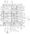
- Fig. 1 shows a 3/2-way valve.
- the valve essentially consists of a drive element 1, a valve slide 2 and a valve housing 3 with a valve body 4 and a housing 5.
- the drive element 1 is an electrodynamic drive as described in EP-A-0 570 649. A detailed description and illustration of the same is therefore omitted.
- the valve spool 2 is rod-shaped with an essentially round cross section and connected to the drive element 1 at one end.
- the valve spool 2 has two control edges 6, 7 which control the flow of the pressure medium and a first and second auxiliary control edge 8, 9, the function of which will be explained later.
- a section 10 is provided which has a smaller outside diameter than the outside diameter of the valve slide 2, so that a flow chamber 11 with an annular cross section is formed.
- a section 12 with a reduced cross section is provided to form the first and second auxiliary control edges 8, 9, which section has a round section 13 and a flattened section 14.
- a groove 15 is formed adjacent to the second auxiliary control edge 9 in the flattened section 14.
- the valve body 4 is a cylindrical body with an axial through bore 21, in which the valve slide 2 is displaceable.
- groove-shaped recesses 22 are formed at a distance from one another.
- bores 23 there are 4 bores 23 in the valve body, each of which connects the recesses 22 with the through-bore 21 and a recess 24 is provided.
- the housing 5 has two sub-housings 26, 27, which are connected by suitable connecting elements (not shown).
- the first housing part 26 has a through-bore 28 for receiving the valve body 4, a feed channel 29 which can be connected to a source of pressure medium, a consumer channel 30 and an outlet channel 31 which e.g. can be connected to a container as well as a section of a control channel 32, which opens out from an end face of the first partial housing 26 into the outlet channel 31.
- the second partial housing 27 has means (not shown) for mounting the drive element and the electrical connecting elements (not shown).
- a shoulder 35 is formed on an end face of the partial housing 27, on which the first partial housing 26 is arranged.
- a bore 36 is provided in the second sub-housing 27 and is formed coaxially to the extension 35.
- a second section of the control channel 32 is formed in the second partial housing 27 and connects the first section of the control channel 32 to the bore 36. The second section of the control channel 32 is closed by a closure part 37.
- valve body 4 is inserted in the through hole 28 of the first partial housing 26 and is in contact with a securing ring 39 on one end face.
- a control chamber 40 is thereby formed.
- the valve body 4 is supported on a sleeve 41, which is arranged in the through hole 28 and held by a cover 42, which closes off the first partial housing 26.
- a through hole 43 is provided in the bottom part of the sleeve.
- a second connecting channel 51 is provided which connects the drain channel 31 to a second control chamber 52.
- the function of the 3/2-way valve is described below.
- the valve has two switching positions and is shown in an intermediate position in FIG. 1. If the valve is moved into the switching position by means of the drive element 1, the drain and consumer channel 30, 31 are connected. With this displacement of the valve spool 2, the second auxiliary control edge 9 first overflows the control channel 52 and closes this and the first auxiliary control edge 8 then overflows the mouth of the feed channel 29, so that pressure medium flows into the control chamber 40 via an annular channel 61. Due to the different outside diameters of the valve spool 2 and the section 13, a force is generated which holds the valve spool 2 in the electrically generated switching position.
- the electrical current to excite the drive element can be interrupted immediately after the force occurs, which advantageously shortens the duty cycle.
- the valve If the valve is shifted into the other switching position by means of the drive element 1, the supply and consumer channels 29, 30 are connected. During this displacement, the first auxiliary control edge 8 passes over the mouth of the feed channel 29 and interrupts the connection between the feed channel 29 and the control chamber 40, while the second auxiliary control edge 9 connects the control chamber 40 with the connection channel 32, so that the pressure medium can flow out via the outlet channel 31.
- valve spool 2 is held in the other switching position by means of the force of the spring 55, which acts on the end face of the valve spool 2. This results in the advantage of a defined switching position for a pressure-free valve.
- the valve contains an electromagnetic drive element (1), a valve slide (2), which is connected to the drive element and can be moved in two end positions, a valve housing (3) with a feed channel (29), a consumer channel (30), and an outlet channel (31 ) and a control chamber (40).
- the valve spool connects the consumer and drain channel in the first switch position and the supply and consumer channel in the second switch position.
- a first (8) and a second (9) auxiliary control edge are provided on the valve slide (2).
- a control channel (32) connects the drain channel (31) and the control chamber (40). In the first end position, the control channel is closed and the control chamber communicates with the feed channel (29) in order to hold the valve slide in the first switching position by means of pressure medium.
- control channel (32) In the second switching position, the control channel (32) is open and the flow chamber (11) connects the feed channel (19) to the consumer channel (30), the valve slide being held in the second end position by means of the standing pressure prevailing in the second control chamber (52) .
- the power loss of the drive element is advantageously reduced, so that cooling of the drive element is not necessary and the duty cycle of the drive element is shortened.
Landscapes
- Engineering & Computer Science (AREA)
- General Engineering & Computer Science (AREA)
- Mechanical Engineering (AREA)
- Magnetically Actuated Valves (AREA)
- Multiple-Way Valves (AREA)
Abstract
Description
- Die Erfindung betrifft ein elektromagnetisches Ventil zur Steuerung des Durchflusses eines Druckmediums gemäss dem Oberbegriff des Anspruches 1.
- Bei direkt gesteuerten Ventilen wird der Ventilschieber mittels eines Kraftmotors oder Elektromagnets in die eine oder andere Stellung verschoben und in der jeweiligen Stellung gehalten. Die für die Erzeugung der für die Verschiebung und Halterung ausreichenden Kraft erforderliche elektrische Energiemenge wird zur Hauptsache in Joule'sche-Wärme umgewandelt, so dass die Einschaltdauer eng begrenzt und in der Regel eine Kühlung der Spule erforderlich ist.
- Der Erfindung wie sie in den Ansprüchen gekennzeichnet ist, liegt die Aufgabe zugrunde, ein elektromagnetisches Ventil zu schaffen, bei welchen die genannten Nachteile dadurch behoben sind, dass die jeweils elektrisch erzeugte Stellung des Ventilschiebers durch das Druckmedium aufrechterhalten wird.
- Die mit der Erfindung erzielbaren Vorteile bestehen darin, dass die Einschaltdauer verkürzt wird, so dass Schaltzeiten im Bereich von einer Millisekunde und kleiner liegen.
- Im folgenden wird die Erfindung anhand der beiliegenden Zeichnungen erläutert.
- Es zeigen:
- Fig. 1
- Einen Axialschnitt durch eine Ausführungsform eines erfindungsgemässen Ventils in schematischer Darstellung;
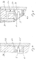
- Fig. 2
- eine Einzelheit A in Fig. 1 im grösseren Massstab;
- Fig. 3
- eine gegenüber der Fig. 1 modifizierte zweite Ausführungsform und
- Fig. 4
- eine Modifikation der ersten und zweiten Ausführungsform.
- Die Fig. 1 zeigt ein 3/2-Wegeventil. Das Ventil besteht im wesentlichen aus einem Antriebselement 1, einem Ventilschieber 2 und einem Ventilgehäuse 3 mit einem Ventilkörper 4 und einem Gehäuse 5. Das Antriebselement 1 ist ein elektrodynamischer Antrieb wie er in der EP-A-0 570 649 beschrieben ist. Deshalb wird auf eine ausführliche Beschreibung und Darstellung desselben verzichtet.
- Der Ventilschieber 2 ist stabförmig mit im wesentlichen rundem Querschnitt und an einem Ende mit dem Antriebselement 1 verbunden. Der Ventilschieber 2 weist zwei Steuerkanten 6, 7, die den Durchfluss des Druckmediums steuern und eine erste und zweite Hilfssteuerkante 8, 9 auf, deren Funktion später erläutert wird.
- Zur Ausbildung der zwei Steuerkanten 6, 7 ist ein Abschnitt 10 vorgesehen, der einen gegenüber dem Aussendurchmesser des Ventilschiebers 2 geringeren Aussendurchmesser hat, so dass eine Durchflusskammer 11 mit ringförmigem Querschnitt gebildet wird.
- Wie die Fig. 2 zeigt, ist zur Ausbildung der ersten und zweiten Hilfssteuerkante 8, 9 ist ein Abschnitt 12 mit einem reduzierten Querschnitt vorgesehen, der einen runden Abschnitt 13 und einen abgeflachten Abschnitt 14 aufweist. Zusätzlich ist eine Rille 15 angrenzend an der zweiten Hilfssteuerkante 9 im abgeflachten Abschnitt 14 ausgebildet.
- Der Ventilkörper 4 ist ein zylindrischer Körper mit einer axialen Durchbohrung 21, in welcher der Ventilschieber 2 verschiebbar ist. In der Mantelfläche des Ventilkörpers 4 sind rinnenförmige Ausnehmungen 22 im Abstand zueinander ausgebildet. Ferner sind im Ventilkörper 4 Bohrungen 23, welche jeweils die Ausnehmungen 22 mit der Durchbohrung 21 verbinden und eine Ausnehmung 24 vorgesehen.
- Das Gehäuse 5 weist zwei Teilgehäuse 26, 27 auf, die durch geeignete Verbindungselemente (nicht dargestellt) verbunden sind. Der erste Gehäuseteil 26 weist eine Durchbohrung 28 zur Aufnahme des Ventilkörpers 4, einen Zuführkanal 29, der mit einer Quelle für Druckmedium verbunden werden kann, einen Verbraucherkanal 30 und einen Ablaufkanal 31, der z.B. mit einem Behälter verbunden werden kann sowie einen Abschnitt eines Steuerkanals 32 auf, der ausgehend von einer Stirnseite des ersten Teilgehäuses 26 in den Ablaufkanal 31 mündet.
- Das zweite Teilgehäuse 27 weist Mittel (nicht dargestellt) zur Montage des Antriebselementes und der elektrischen Verbindungselemente (nicht dargestellt) auf.
- An einer Stirnseite des Teilgehäuses 27 ist ein Ansatz 35 ausgebildet, auf welchem das erste Teilgehäuse 26 angeordnet ist. Im zweiten Teilgehäuse 27 ist eine Bohrung 36 vorgesehen, die koaxial zum Ansatz 35 ausgebildet ist. Im zweiten Teilgehäuse 27 ist ein zweiter Abschnitt des Steuerkanals 32 ausgebildet, welcher den ersten Abschnitt des Steuerkanals 32 mit der Bohrung 36 verbindet. Der zweite Abschnitt des Steuerkanals 32 ist durch einen Verschlussteil 37 abgeschlossen.
- Wie die Fig. 1 zeigt, ist der Ventilkörper 4 in der Durchbohrung 28 des ersten Teilgehäuses 26 eingesetzt und liegt an einer Stirnseite an einen Sicherungsring 39 an. Dadurch wird eine Steuerkammer 40 gebildet. An der anderen Stirnseite ist der Ventilkörper 4 an einer Büchse 41 abgestützt, die in die Durchbohrung 28 angeordnet und durch einen Deckel 42 gehalten ist, welcher das erste Teilgehäuse 26 abschliesst. Im Bodenteil der Büchse ist ein Durchgangsloch 43 vorgesehen.
- Wie die Fig. 3 zeigt, ist bei dieser Ausführungsform des Ventils ein zweiter Verbindungskanal 51 vorgesehen, der den Ablaufkanal 31 mit einer zweiten Steuerkammer 52 verbindet.
- Nachfolgend wird die Funktion des 3/2-Wegeventils beschrieben. Für die Funktion des Ventils ist das Anliegen eines Druckmediums im Zuführkanal 29 erforderlich. Das Ventil hat zwei Schaltstellungen und ist in der Fig. 1 in einer Zwischenstellung dargestellt. Wird das Ventil mittels dem Antriebselement 1 in die Schaltstellung verschoben, so werden der Ablauf- und Verbraucherkanal 30, 31 verbunden. Bei dieser Verschiebung des Ventilschiebers 2 überläuft die zweite Hilfssteuerkante 9 zuerst den Steuerkanal 52 und verschliesst diesen und die erste Hilfssteuerkante 8 überläuft danach die Mündung des Zuführkanals 29, so dass Druckmedium über einen ringförmigen Kanal 61 in die Steuerkammer 40 strömt. Aufgrund der unterschiedlichen Aussendurchmesser des Ventilschiebers 2 und des Abschnittes 13 wird eine Kraft erzeugt, welche den Ventilschieber 2 in der elektrisch erzeugten Schaltstellung hält.
- Der elektrische Strom zur Erregung des Antriebselementes kann unmittelbar nach Auftreten der Kraft unterbrochen werden, wodurch die Einschaltdauer in vorteilhafter Weise verkürzt wird.
- Wird das Ventil mittels dem Antriebselement 1 in die andere Schaltstellung verschoben, so werden der Zuführ- und der Verbraucherkanal 29, 30 verbunden. Bei dieser Verschiebung überfährt die erste Hilfssteuerkante 8 die Mündung des Zuführkanals 29 und unterbricht die Verbindung zwischen dem Zuführkanal 29 und Steuerkammer 40 während die zweite Hilfssteuerkante 9 die Steuerkammer 40 mit dem Verbindungskanal 32 verbindet, so dass das Druckmedium über den Ablaufkanal 31 abströmen kann.
- Da in hydraulischen System aus hydraulischen Gründen im Ablauf in der Regel ein gewisser Standdruck herrscht, wirkt dieser über den Kanal 53 die Verbindungsbohrung 54 in der Steuerkammer 52 auf das in diese hineinragende Ende der Ventilspindel 2 und hält diese in der anderen Schaltstellung.
- Bei der Ausführungsform gemäss Fig. 4 wird der Ventilschieber 2 mittels der Kraft der Feder 55, welche auf die Stirnfläche des Ventilschiebers 2 einwirkt, in der anderen Schaltstellung gehalten. Daraus ergibt sich der Vorteil einer definierten Schaltstellung für ein druckloses Ventil.
- Das Ventil enthält ein elektromagnetisches Antriebselement (1), einen Ventilschieber (2), der mit dem Antriebselement verbunden und in zwei Endstellungen verschiebbar ist, ein Ventilgehäuse (3) mit einem Zuführkanal (29), einen Verbraucherkanal (30), einem Ablaufkanal (31) und einer Steuerkammer (40). Der Ventilschieber verbindet in der ersten Schaltstellung den Verbraucher- und Ablaufkanal und in der zweiten Schaltstellung den Zuführ- und Verbraucherkanal. Am Ventilschieber (2) sind eine erste (8) und eine zweite (9) Hilfssteuerkante vorgesehen. Ein Steuerkanal (32) verbindet den Ablaufkanal (31) und die Steuerkammer (40). In der ersten Endstellung ist der Steuerkanal geschlossen und die Steuerkammer kommuniziert mit dem Zuführkanal (29), um den Ventilschieber mittels Druckmedium in der ersten Schaltstellung zu halten. In der zweiten Schaltstellung ist der Steuerkanal (32) geöffnet und die Durchlaufkammer (11) verbindet den Zuführkanal (19) mit dem Verbraucherkanal (30), wobei der Ventilschieber mittels des in der zweiten Steuerkammer (52) herrschenden Standdruckes in der zweiten Endstellung gehalten wird. Durch die Halterung des Ventilschiebers mittels des Druckmediums wird in vorteilhafterweise die Verlustleistung des Antriebselementes verringert, so dass eine Kühlung desselben nicht erforderlich ist und die Einschaltdauer des Antriebselementes verkürzt wird.
Claims (7)
- Elektromagnetisches Ventil zur Steuerung des Durchflusses eines Druckmediums, mit einem Antriebselement (1), einem Ventilgehäuse (3), mindestens einem Zuführkanal (29) für das Druckmedium und mindestens einem weiteren Kanal (30, 31), die im Ventilgehäuse ausgebildet sind und mit einem Ventilschieber (2), der mit dem Antriebselement (1) verbunden und im Ventilgehäuse axial verschiebbar angeordnet ist, wobei der Ventilschieber in seinen Schaltstellungen die Verbindung zwischen dem Zuführkanal und dem weiteren Kanal herstellt bzw. unterbricht, dadurch gekennzeichnet, dass eine erste (8) und zweite (9) Hilfssteuerkante am Ventilschieber (2) vorgesehen sind und dass eine Steuerkammer (40) und ein Steuerkanal (42) im Ventilgehäuse (3, 4) vorgesehen ist, welcher Steuerkanal den weiteren Kanal (31) und die Steuerkammer (40) verbindet, wobei der Steuerkanal in der einen Schaltstellung des Ventilschiebers geschlossen ist und die Steuerkammer mit dem Zuführkanal (29) kommuniziert, um den Ventilschieber mittels Druckmedium in der Schaltstellung zu halten und wobei in der zweiten Schaltstellung des Ventilschiebers der Steuerkanal (32) geöffnet und die Verbindung zwischen der Steuerkammer (40) und mit dem Zuführkanal (29) unterbrochen ist, so dass der Ventilschieber mittels des in der Steuerkammer 52 herrschenden Standdruckes in der zweiten Schaltstellung gehalten wird.
- Ventil nach Anspruch 1, gekennzeichnet durch ein federelastisches Element (55), welches in der zweiten Steuerkammer (53) angeordnet ist.
- Ventil nach einem der Ansprüche 1 oder 2, gekennzeichnet durch ein Ventilgehäuse (3), welches ein Gehäuse (3) mit dem Zuführkanal und dem weiteren Kanal (30, 31) und einen Ventilkörper (4) aufweist, der eine axiale Durchbohrung (21) zur Aufnahme des Ventilschiebers (2), ringförmige Ausnehmungen (22), die mit dem Zuführkanal und dem weiteren Kanal (30, 31) kommunizieren und Bohrungen (23) aufweist, derart, dass jede Ausnehmung (22) mit der Durchbohrung (21) verbunden ist.
- Ventil nach Anspruch 3, dadurch gekennzeichnet, dass ein Verbindungskanal (32) vorgesehen ist, der im Ventilgehäuse (3) ausgebildet ist, um den weiteren Kanal (31) mit der Steuerkammer (40) zu verbinden.
- Ventil nach einem der Ansprüche 3 oder 4, gekennzeichnet durch eine zweite Steuerkammer (52) und durch einen Hilfskanal (51), welcher den weiteren Kanal (31) mit der zweiten Steuerkammer (52) verbindet.
- Ventil nach einem der Ansprüche 1 bis 4, dadurch gekennzeichnet, dass das Ventil ein 3/2-Wegeventil ist und dass das Ventil ein Ventilgehäuse (3) einen Zuführ-, einen Verbraucher- und einen Ablaufkanal (29, 30, 31), die mit dem Ventilschieber (2) in Verbindung stehen sowie einen Verbindungskanal (32) aufweist, welche den Ablaufkanal (31) mit der Steuerkammer (40) verbindet.
- Ventil nach Anspruch 6, gekennzeichnet durch eine zweite Steuerkammer (52) und durch einen Hilfskanal (53), welcher den Ablaufkanal (31) mit der zweiten Steuerkammer (52) verbindet.
Priority Applications (6)
| Application Number | Priority Date | Filing Date | Title |
|---|---|---|---|
| DK96810233T DK0802357T3 (da) | 1996-04-15 | 1996-04-15 | Elektromagnetisk ventil |
| DE59604369T DE59604369D1 (de) | 1996-04-15 | 1996-04-15 | Elektromagnetisches Ventil |
| EP19960810233 EP0802357B1 (de) | 1996-04-15 | 1996-04-15 | Elektromagnetisches Ventil |
| JP01497897A JP3854677B2 (ja) | 1996-04-15 | 1997-01-29 | 電磁バルブ |
| KR1019970011555A KR100461935B1 (ko) | 1996-04-15 | 1997-03-31 | 전자밸브 |
| CN97110793A CN1086021C (zh) | 1996-04-15 | 1997-04-14 | 电磁阀 |
Applications Claiming Priority (1)
| Application Number | Priority Date | Filing Date | Title |
|---|---|---|---|
| EP19960810233 EP0802357B1 (de) | 1996-04-15 | 1996-04-15 | Elektromagnetisches Ventil |
Publications (2)
| Publication Number | Publication Date |
|---|---|
| EP0802357A1 true EP0802357A1 (de) | 1997-10-22 |
| EP0802357B1 EP0802357B1 (de) | 2000-02-02 |
Family
ID=8225588
Family Applications (1)
| Application Number | Title | Priority Date | Filing Date |
|---|---|---|---|
| EP19960810233 Expired - Lifetime EP0802357B1 (de) | 1996-04-15 | 1996-04-15 | Elektromagnetisches Ventil |
Country Status (6)
| Country | Link |
|---|---|
| EP (1) | EP0802357B1 (de) |
| JP (1) | JP3854677B2 (de) |
| KR (1) | KR100461935B1 (de) |
| CN (1) | CN1086021C (de) |
| DE (1) | DE59604369D1 (de) |
| DK (1) | DK0802357T3 (de) |
Cited By (2)
| Publication number | Priority date | Publication date | Assignee | Title |
|---|---|---|---|---|
| WO2000017552A1 (en) * | 1998-09-23 | 2000-03-30 | Lucas Industries Public Limited Company | Improved solenoid controlled valve |
| KR100461935B1 (ko) * | 1996-04-15 | 2005-04-19 | 베르트질레 슈바이츠 악티엔게젤샤프트 | 전자밸브 |
Families Citing this family (3)
| Publication number | Priority date | Publication date | Assignee | Title |
|---|---|---|---|---|
| CN102979581A (zh) * | 2011-09-07 | 2013-03-20 | 广州派莎克流体设备技术有限公司 | 往复运动式气马达配气阀 |
| CN104676045B (zh) * | 2015-03-11 | 2017-03-15 | 北京大漠石油工程技术有限公司 | 一种水介质两位三通换向阀 |
| CN116412269A (zh) * | 2021-12-31 | 2023-07-11 | 中国科学院理化技术研究所 | 电磁阀 |
Citations (5)
| Publication number | Priority date | Publication date | Assignee | Title |
|---|---|---|---|---|
| DE1614315A1 (de) * | 1967-01-30 | 1970-05-21 | Zenny Olsen | Elektromagnetischer Antrieb fuer Servo-Absperrorgan |
| US4250922A (en) * | 1978-05-24 | 1981-02-17 | Robert Bosch Gmbh | Electromagnetically operated control valve |
| WO1982001401A1 (en) * | 1980-10-17 | 1982-04-29 | Golan Kenneth F | Valve actuator with hydraulic latching |
| US4364412A (en) * | 1980-11-10 | 1982-12-21 | W-K-M Wellhead Systems, Inc. | Pull type relay valve with automatic lockout |
| EP0570649A1 (de) * | 1992-05-19 | 1993-11-24 | New Sulzer Diesel Ag | Vorrichtung zum Steuern des Durchflusses eines hydraulischen Druckmittels, insbesondere für die Brennstoffeinspritzung einer Hubkolbenbrennkraftmaschine |
Family Cites Families (5)
| Publication number | Priority date | Publication date | Assignee | Title |
|---|---|---|---|---|
| DE2403770A1 (de) * | 1974-01-26 | 1975-08-14 | Bosch Gmbh Robert | Elektromagnetische 3-wege-ventilanordnung |
| JPS50153321A (de) * | 1974-05-31 | 1975-12-10 | ||
| JPH032983A (ja) * | 1989-05-30 | 1991-01-09 | Babcock Hitachi Kk | 画像処理方法 |
| JPH0717898Y2 (ja) * | 1989-07-13 | 1995-04-26 | カヤバ工業株式会社 | 比例電磁式圧力制御弁 |
| DE59604369D1 (de) * | 1996-04-15 | 2000-03-09 | Waertsilae Nsd Schweiz Ag | Elektromagnetisches Ventil |
-
1996
- 1996-04-15 DE DE59604369T patent/DE59604369D1/de not_active Expired - Lifetime
- 1996-04-15 EP EP19960810233 patent/EP0802357B1/de not_active Expired - Lifetime
- 1996-04-15 DK DK96810233T patent/DK0802357T3/da active
-
1997
- 1997-01-29 JP JP01497897A patent/JP3854677B2/ja not_active Expired - Fee Related
- 1997-03-31 KR KR1019970011555A patent/KR100461935B1/ko not_active Expired - Fee Related
- 1997-04-14 CN CN97110793A patent/CN1086021C/zh not_active Expired - Fee Related
Patent Citations (5)
| Publication number | Priority date | Publication date | Assignee | Title |
|---|---|---|---|---|
| DE1614315A1 (de) * | 1967-01-30 | 1970-05-21 | Zenny Olsen | Elektromagnetischer Antrieb fuer Servo-Absperrorgan |
| US4250922A (en) * | 1978-05-24 | 1981-02-17 | Robert Bosch Gmbh | Electromagnetically operated control valve |
| WO1982001401A1 (en) * | 1980-10-17 | 1982-04-29 | Golan Kenneth F | Valve actuator with hydraulic latching |
| US4364412A (en) * | 1980-11-10 | 1982-12-21 | W-K-M Wellhead Systems, Inc. | Pull type relay valve with automatic lockout |
| EP0570649A1 (de) * | 1992-05-19 | 1993-11-24 | New Sulzer Diesel Ag | Vorrichtung zum Steuern des Durchflusses eines hydraulischen Druckmittels, insbesondere für die Brennstoffeinspritzung einer Hubkolbenbrennkraftmaschine |
Cited By (4)
| Publication number | Priority date | Publication date | Assignee | Title |
|---|---|---|---|---|
| KR100461935B1 (ko) * | 1996-04-15 | 2005-04-19 | 베르트질레 슈바이츠 악티엔게젤샤프트 | 전자밸브 |
| WO2000017552A1 (en) * | 1998-09-23 | 2000-03-30 | Lucas Industries Public Limited Company | Improved solenoid controlled valve |
| US6481332B2 (en) | 1998-09-23 | 2002-11-19 | Lucas Industries Limited | Solenoid controlled valve |
| US6745665B2 (en) | 1998-09-23 | 2004-06-08 | Lucas Industries Limited | Solenoid controlled valve |
Also Published As
| Publication number | Publication date |
|---|---|
| EP0802357B1 (de) | 2000-02-02 |
| JPH09317928A (ja) | 1997-12-12 |
| KR970070677A (ko) | 1997-11-07 |
| DE59604369D1 (de) | 2000-03-09 |
| CN1086021C (zh) | 2002-06-05 |
| DK0802357T3 (da) | 2000-05-01 |
| JP3854677B2 (ja) | 2006-12-06 |
| KR100461935B1 (ko) | 2005-04-19 |
| CN1167885A (zh) | 1997-12-17 |
Similar Documents
| Publication | Publication Date | Title |
|---|---|---|
| DE60012266T2 (de) | Vorgesteuertes Steuerventil | |
| DE69704045T2 (de) | Steuerventilverteilerplatte mit innerer oder äusserer Steuerschaltung | |
| DE3119445A1 (de) | "elektro-hydraulisches steuerventil" | |
| EP0681128A1 (de) | Magnetventil | |
| DE3406794A1 (de) | Druckregelventil | |
| DE19731402A1 (de) | Elektromagnetventileinrichtung | |
| WO1996002782A1 (de) | Modulares ventil system für strömende medien | |
| DE102016115020A1 (de) | Druckdämpfungsvorrichtung | |
| EP1212517B1 (de) | Nockenwellenversteller für brennkraftmaschinen | |
| DE10300514A1 (de) | Durchflußwegstruktur eines Hohlrohrs | |
| DE69617591T2 (de) | Direkt gekuppeltes Magnetventil | |
| DE3542131A1 (de) | Ventilvorrichtung | |
| WO1999046528A1 (de) | Magnetventil | |
| DE3224189A1 (de) | Hydraulisches system mit elektrischer proportionalsteuerung | |
| DE3134065A1 (de) | Druckregelventil | |
| DE3503785A1 (de) | Magnetventil, insbesondere fuer hydraulische steuerungen | |
| DE4317706C2 (de) | Fremdkraftbetätigtes Wege-Sitzventil | |
| EP0802357B1 (de) | Elektromagnetisches Ventil | |
| EP0461736A2 (de) | Ventileinrichtung | |
| AT398114B (de) | Proportional-wegeventil | |
| DE10146497A1 (de) | Elektromagnetisches Steuerventil | |
| DE19946996A1 (de) | Solenoid-gesteuertes Ventil | |
| EP1218630A2 (de) | Einspritzventil, insbesondere für common-rail-einspriztsysteme | |
| DE1775134A1 (de) | Schieberventil fuer ein Druckmedium | |
| DE3430724A1 (de) | Spulenbetaetigtes hydraulikventil |
Legal Events
| Date | Code | Title | Description |
|---|---|---|---|
| PUAI | Public reference made under article 153(3) epc to a published international application that has entered the european phase |
Free format text: ORIGINAL CODE: 0009012 |
|
| AK | Designated contracting states |
Kind code of ref document: A1 Designated state(s): DE DK FI FR IT NL |
|
| AX | Request for extension of the european patent |
Free format text: LT;SI |
|
| RBV | Designated contracting states (corrected) |
Designated state(s): DE DK FI FR IT NL |
|
| 17P | Request for examination filed |
Effective date: 19980324 |
|
| 17Q | First examination report despatched |
Effective date: 19980818 |
|
| GRAG | Despatch of communication of intention to grant |
Free format text: ORIGINAL CODE: EPIDOS AGRA |
|
| GRAG | Despatch of communication of intention to grant |
Free format text: ORIGINAL CODE: EPIDOS AGRA |
|
| GRAH | Despatch of communication of intention to grant a patent |
Free format text: ORIGINAL CODE: EPIDOS IGRA |
|
| GRAH | Despatch of communication of intention to grant a patent |
Free format text: ORIGINAL CODE: EPIDOS IGRA |
|
| GRAA | (expected) grant |
Free format text: ORIGINAL CODE: 0009210 |
|
| AK | Designated contracting states |
Kind code of ref document: B1 Designated state(s): DE DK FI FR IT NL |
|
| REF | Corresponds to: |
Ref document number: 59604369 Country of ref document: DE Date of ref document: 20000309 |
|
| ITF | It: translation for a ep patent filed | ||
| ET | Fr: translation filed | ||
| REG | Reference to a national code |
Ref country code: DK Ref legal event code: T3 |
|
| PLBE | No opposition filed within time limit |
Free format text: ORIGINAL CODE: 0009261 |
|
| STAA | Information on the status of an ep patent application or granted ep patent |
Free format text: STATUS: NO OPPOSITION FILED WITHIN TIME LIMIT |
|
| 26N | No opposition filed | ||
| PGFP | Annual fee paid to national office [announced via postgrant information from national office to epo] |
Ref country code: NL Payment date: 20090415 Year of fee payment: 14 Ref country code: IT Payment date: 20090428 Year of fee payment: 14 Ref country code: FR Payment date: 20090414 Year of fee payment: 14 Ref country code: FI Payment date: 20090417 Year of fee payment: 14 |
|
| REG | Reference to a national code |
Ref country code: NL Ref legal event code: V1 Effective date: 20101101 |
|
| REG | Reference to a national code |
Ref country code: FR Ref legal event code: ST Effective date: 20101230 |
|
| PG25 | Lapsed in a contracting state [announced via postgrant information from national office to epo] |
Ref country code: NL Free format text: LAPSE BECAUSE OF NON-PAYMENT OF DUE FEES Effective date: 20101101 Ref country code: FI Free format text: LAPSE BECAUSE OF NON-PAYMENT OF DUE FEES Effective date: 20100415 |
|
| PG25 | Lapsed in a contracting state [announced via postgrant information from national office to epo] |
Ref country code: IT Free format text: LAPSE BECAUSE OF NON-PAYMENT OF DUE FEES Effective date: 20100415 |
|
| PG25 | Lapsed in a contracting state [announced via postgrant information from national office to epo] |
Ref country code: FR Free format text: LAPSE BECAUSE OF NON-PAYMENT OF DUE FEES Effective date: 20100430 |
|
| PGFP | Annual fee paid to national office [announced via postgrant information from national office to epo] |
Ref country code: DK Payment date: 20130418 Year of fee payment: 18 Ref country code: DE Payment date: 20130419 Year of fee payment: 18 |
|
| REG | Reference to a national code |
Ref country code: DE Ref legal event code: R119 Ref document number: 59604369 Country of ref document: DE |
|
| REG | Reference to a national code |
Ref country code: DK Ref legal event code: EBP Effective date: 20140430 |
|
| REG | Reference to a national code |
Ref country code: DE Ref legal event code: R119 Ref document number: 59604369 Country of ref document: DE Effective date: 20141101 |
|
| PG25 | Lapsed in a contracting state [announced via postgrant information from national office to epo] |
Ref country code: DE Free format text: LAPSE BECAUSE OF NON-PAYMENT OF DUE FEES Effective date: 20141101 |
|
| PG25 | Lapsed in a contracting state [announced via postgrant information from national office to epo] |
Ref country code: DK Free format text: LAPSE BECAUSE OF NON-PAYMENT OF DUE FEES Effective date: 20140430 |