EP0802357B1 - Elektromagnetisches Ventil - Google Patents
Elektromagnetisches Ventil Download PDFInfo
- Publication number
- EP0802357B1 EP0802357B1 EP19960810233 EP96810233A EP0802357B1 EP 0802357 B1 EP0802357 B1 EP 0802357B1 EP 19960810233 EP19960810233 EP 19960810233 EP 96810233 A EP96810233 A EP 96810233A EP 0802357 B1 EP0802357 B1 EP 0802357B1
- Authority
- EP
- European Patent Office
- Prior art keywords
- valve
- passage
- control
- control chamber
- slider
- Prior art date
- Legal status (The legal status is an assumption and is not a legal conclusion. Google has not performed a legal analysis and makes no representation as to the accuracy of the status listed.)
- Expired - Lifetime
Links
Images


Classifications
-
- F—MECHANICAL ENGINEERING; LIGHTING; HEATING; WEAPONS; BLASTING
- F16—ENGINEERING ELEMENTS AND UNITS; GENERAL MEASURES FOR PRODUCING AND MAINTAINING EFFECTIVE FUNCTIONING OF MACHINES OR INSTALLATIONS; THERMAL INSULATION IN GENERAL
- F16K—VALVES; TAPS; COCKS; ACTUATING-FLOATS; DEVICES FOR VENTING OR AERATING
- F16K31/00—Actuating devices; Operating means; Releasing devices
- F16K31/02—Actuating devices; Operating means; Releasing devices electric; magnetic
- F16K31/06—Actuating devices; Operating means; Releasing devices electric; magnetic using a magnet, e.g. diaphragm valves, cutting off by means of a liquid
- F16K31/0603—Multiple-way valves
- F16K31/061—Sliding valves
- F16K31/0613—Sliding valves with cylindrical slides
-
- F—MECHANICAL ENGINEERING; LIGHTING; HEATING; WEAPONS; BLASTING
- F16—ENGINEERING ELEMENTS AND UNITS; GENERAL MEASURES FOR PRODUCING AND MAINTAINING EFFECTIVE FUNCTIONING OF MACHINES OR INSTALLATIONS; THERMAL INSULATION IN GENERAL
- F16K—VALVES; TAPS; COCKS; ACTUATING-FLOATS; DEVICES FOR VENTING OR AERATING
- F16K11/00—Multiple-way valves, e.g. mixing valves; Pipe fittings incorporating such valves
- F16K11/02—Multiple-way valves, e.g. mixing valves; Pipe fittings incorporating such valves with all movable sealing faces moving as one unit
- F16K11/06—Multiple-way valves, e.g. mixing valves; Pipe fittings incorporating such valves with all movable sealing faces moving as one unit comprising only sliding valves, i.e. sliding closure elements
- F16K11/065—Multiple-way valves, e.g. mixing valves; Pipe fittings incorporating such valves with all movable sealing faces moving as one unit comprising only sliding valves, i.e. sliding closure elements with linearly sliding closure members
- F16K11/07—Multiple-way valves, e.g. mixing valves; Pipe fittings incorporating such valves with all movable sealing faces moving as one unit comprising only sliding valves, i.e. sliding closure elements with linearly sliding closure members with cylindrical slides
- F16K11/0704—Multiple-way valves, e.g. mixing valves; Pipe fittings incorporating such valves with all movable sealing faces moving as one unit comprising only sliding valves, i.e. sliding closure elements with linearly sliding closure members with cylindrical slides comprising locking elements
-
- F—MECHANICAL ENGINEERING; LIGHTING; HEATING; WEAPONS; BLASTING
- F16—ENGINEERING ELEMENTS AND UNITS; GENERAL MEASURES FOR PRODUCING AND MAINTAINING EFFECTIVE FUNCTIONING OF MACHINES OR INSTALLATIONS; THERMAL INSULATION IN GENERAL
- F16K—VALVES; TAPS; COCKS; ACTUATING-FLOATS; DEVICES FOR VENTING OR AERATING
- F16K31/00—Actuating devices; Operating means; Releasing devices
- F16K31/02—Actuating devices; Operating means; Releasing devices electric; magnetic
- F16K31/06—Actuating devices; Operating means; Releasing devices electric; magnetic using a magnet, e.g. diaphragm valves, cutting off by means of a liquid
- F16K31/0686—Braking, pressure equilibration, shock absorbing
Definitions
- the invention relates to an electromagnetic valve for Control of the flow of a pressure medium according to the The preamble of claim 1 and / or 2.
- a valve is e.g. known from EP-A-570 649.
- the valve spool is used for directly controlled valves by means of a power motor or electromagnet in one or another position shifted and in the respective Position held.
- the for the generation of the for the Movement and bracket sufficient force required amount of electrical energy becomes The main thing converted into Joule heat, so that Duty cycle narrowly limited and usually cooling the coil is required.
- the underlying task is an electromagnetic one To create a valve in which the disadvantages mentioned are remedied that the each electrically generated position of the valve spool by the Pressure medium or is maintained by a resilient element.
- Fig. 1 shows a 3/2-way valve.
- the valve (3) exists essentially from a drive element 1, a Valve slide 2 and a valve housing 5 with a Valve body 4.
- the drive element 1 is an electrodynamic drive like the one in the EP-A-0 570 649. That is why a detailed description and illustration of the same waived.
- the valve spool 2 is essentially rod-shaped round cross section and at one end with the Drive element 1 connected.
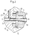
- the valve spool 2 has two control edges 6, 7, the flow of the Control media and a first and second Auxiliary control edge 8, 9, whose function later is explained.
- a Section 10 provided one against the Reduce the outside diameter of the valve spool 2 Has outside diameter so that a flow chamber 11 is formed with an annular cross section.
- the first and a second control edge 8, 9 is a section 12 with a reduced cross-section provided that one round section 13 and a flattened section 14 having.
- a groove 15 is adjacent to the second auxiliary control edge 9 in the flattened section 14 educated.
- the valve body 4 is a cylindrical body with a axial through hole 21, in which the valve spool 2 is movable.
- the valve body 4 In the lateral surface of the valve body 4 are groove-shaped recesses 22 at a distance from each other educated.
- the valve housing 5 has two sub-housings 26, 27 which by suitable connecting elements (not shown) are connected.
- the first housing part 26 has one Bore 28 for receiving the valve body 4, a Feed channel 29 which is connected to a source of pressure medium can be connected to a consumer channel 30 and a drain channel 31 which e.g. with a container can be connected as well as a section of a Control channel 32 on, starting from one end of the first partial housing 26 opens into the drain channel 31.
- the second partial housing 27 has means (not shown) for mounting the drive element and the electrical connecting elements (not shown).
- the partial housing 27 At one end of the partial housing 27 there is an extension 35 on which the first partial housing 26 is arranged.
- the second partial housing 27 there is one Bore 36 is provided, which is coaxial to the neck 35 is trained.
- a second section of the control channel 32 is formed, which the first section of the control channel 32 with the Hole 36 connects.
- the second section of the Control channel 32 is through a closure part 37 completed.
- valve body 4 is in the Through bore 28 of the first partial housing 26 used and abuts a locking ring 39 on one end face.
- a control chamber 40 is thereby formed.
- the valve body 4 At the the other end is the valve body 4 on a sleeve 41 supported, which is arranged in the through hole 28 and is held by a lid 42 which is the first Partial housing 26 closes.
- a through hole 43 In the bottom part of the rifle is a through hole 43 is provided.
- valve a second connecting channel 51 is provided, the drain channel 31 with a second control chamber 52 connects.
- the function of the 3/2-way valve is shown below described. That is for the function of the valve Application of a pressure medium in the feed channel 29 required.
- the valve 3 has two switch positions and is shown in Fig. 1 in an intermediate position. If the valve by means of the drive element 1 in the Switch position shifted, so the sequence and Consumer channel 30, 31 connected. At this Displacement of the valve spool 2 overflows the second Auxiliary control edge 9 first the control channel 32 and closes this and the first auxiliary control edge 8 then overflows the mouth of the feed channel 29, so that Print medium via an annular channel 61 in the Control chamber 40 flows. Because of the different Outside diameter of the valve spool 2 and Section 13 generates a force that the Valve slide 2 in the electrically generated Switch position holds.
- the electric current to excite the drive element can be interrupted immediately after the force occurs be, thereby the duty cycle in an advantageous manner is shortened.
- the connecting bore 54 acts via the channel 51 in the control chamber 52 to the protruding into it End of valve stem 2 and holds it in the other Switch position.
- the valve 3 contains an electromagnetic Drive element 1, a valve spool 2, with the Drive element connected and in two end positions is displaceable, a valve housing 5 with a Feed channel 29, a consumer channel 30, one Drain channel 31 and a control chamber 40.
- Der Valve spool connects the in the first switching position Consumer and drainage channel and in the second Switch position the feed and consumer channel.
- At the Valve spools 2 are a first 8 and a second 9 Auxiliary control edge provided.
- a control channel 32 connects the drain channel 31 and the control chamber 40. In the first The control channel is closed and the Control chamber communicates with the feed channel 29 around the Valve slide using pressure medium in the first Hold switch position.
- the control channel 32 In the second switch position the control channel 32 is open and the flow chamber 11 connects the feed channel 29 to the consumer channel 30, wherein the valve spool by means of the in the second Control chamber 52 prevailing stand pressure in the second End position is held.
Landscapes
- Engineering & Computer Science (AREA)
- General Engineering & Computer Science (AREA)
- Mechanical Engineering (AREA)
- Magnetically Actuated Valves (AREA)
- Multiple-Way Valves (AREA)
Description
- Fig. 1
- Einen Axialschnitt durch eine Ausführungsform eines erfindungsgemässen Ventils in schematischer Darstellung;
- Fig. 2
- eine Einzelheit A in Fig. 1 im grösseren Massstab;
- Fig. 3
- eine gegenüber der Fig. 1 modifizierte zweite Ausführungsform und
- Fig. 4
- eine Modifikation der ersten und zweiten Ausführungsform.
Claims (6)
- Elektromagnetisches Ventil (3) zur Steuerung des Durchflusses eines Druckmediums, mit einem Antriebselement (1), einem Ventilgehäuse (5), mindestens einem Zuführkanal (29) für das Druckmedium und mindestens einem weiteren Kanal (30, 31), die im Ventilgehäuse ausgebildet sind und mit einem Ventilschieber (2), der mit dem Antriebselement (1) verbunden und im Ventilgehäuse axial verschiebbar angeordnet ist, wobei der Ventilschieber in seinen Schaltstellungen die Verbindung zwischen dem Zuführkanal und einem weiteren Kanal (30) herstellt bzw. unterbricht, dadurch gekennzeichnet, dass eine erste (8) und zweite (9) Hilfssteuerkante am Ventilschieber (2) vorgesehen sind und dass eine erste Steuerkammer (40) und ein Steuerkanal (32) im Ventilgehäuse (5) vorgesehen ist, welcher Steuerkanal einen weiteren Kanal (31) und die erste Steuerkammer (40) verbindet, wobei der Steuerkanal in der einen Schaltstellung des Ventilschiebers geschlossen ist und die erste Steuerkammer mit dem Zuführkanal (29) kommuniziert, um den Ventilschieber mittels Druckmedium in der Schaltstellung zu halten und wobei in der zweiten Schaltstellung des Ventilschiebers der Steuerkanal (32) geöffnet und die Verbindung zwischen der ersten Steuerkammer (40) und dem Zuführkanal (29) unterbrochen ist, so dass über einen Hilfskanal (51) ein Standdruck in der zweiten Steuerkammer (52) erzeugt wird, um den Ventilschieber in der zweiten Stellung zu halten.
- Elektromagnetisches Ventil 3 zur Steuerung des Durchflusses eines Druckmediums, mit einem Antriebselement (1), einem Ventilgehäuse (5), mindestens einem Zuführkanal (29) für das Druckmedium und mindestens einem weiteren Kanal (30, 31), die im Ventilgehäuse ausgebildet sind und mit einem Ventilschieber (2), der mit dem Antriebselement (1) verbunden und im Ventilgehäuse axial verschiebbar angeordnet ist, wobei der Ventilschieber in seinen Schaltstellungen die Verbindung zwischen dem Zuführkanal und einem weiteren Kanal (30) herstellt bzw. unterbricht, dadurch gekennzeichnet, dass eine erste (8) und zweite (9) Hilfssteuerkante am Ventilschieber (2) vorgesehen sind, dass eine erste Steuerkammer (40) und ein Steuerkanal (32) im Ventilgehäuse (5) vorgesehen ist, welcher Steuerkanal einen weiteren Kanal (31) und die erste Steuerkammer (40) verbindet, wobei der Steuerkanal in der einen Schaltstellung des Ventilschiebers geschlossen ist und die erste Steuerkammer mit dem Zuführkanal (29) kommuniziert, um den Ventilschieber mittels Druckmedium in der Schaltstellung zu halten und wobei in der zweiten Schaltstellung des Ventilschiebers der Steuerkanal (32) geöffnet und die Verbindung zwischen der ersten Steuerkammer (40) und dem Zuführkanal (29) unterbrochen ist, und dass ein federelastisches Element (55) in einer zweiten Steuerkammer (52) angeordnet ist, um den Ventilschieber in der zweiten Stellung zu halten.
- Ventil nach einem der Ansprüche 1 oder 2,
gekennzeichnet durch ein Ventilgehäuse (5), welches den Zuführkanal und den weiteren Kanal (30, 31) und einen Ventilkörper (4) aufweist, der eine axiale Durchbohrung (21) zur Aufnahme des Ventilschiebers (2), ringförmige Ausnehmungen (22), die mit dem Zuführkanal und dem weiteren Kanal (30, 31) kommunizieren und Bohrungen (23) aufweist, derart, dass jede Ausnehmung (22) mit der Durchbohrung (21) verbunden ist. - Ventil nach Anspruch 3, dadurch gekennzeichnet, dass ein Steuerkanal (32) vorgesehen ist, der im Ventilgehäuse (5) ausgebildet ist, um den weiteren Kanal (31) mit der ersten Steuerkammer (40) zu verbinden.
- Ventil nach einem der Ansprüche 1 bis 4, dadurch gekennzeichnet, dass das Ventil ein 3/2-Wegeventil ist und dass das Ventil ein Ventilgehäuse (5) einen Zuführ-, einen Verbraucher- und einen Ablaufkanal (29, 30, 31), die mit dem Ventilschieber (2) in Verbindung stehen sowie einen Steuerkanal (32) aufweist, welche den Ablaufkanal (31) mit der ersten Steuerkammer (40) verbindet.
- Ventil nach Anspruch 6, dadurch gekennzeichnet, dass der Hilfskanal (51) den Ablaufkanal (31) mit der zweiten Steuerkammer (52) verbindet.
Priority Applications (6)
| Application Number | Priority Date | Filing Date | Title |
|---|---|---|---|
| EP19960810233 EP0802357B1 (de) | 1996-04-15 | 1996-04-15 | Elektromagnetisches Ventil |
| DK96810233T DK0802357T3 (da) | 1996-04-15 | 1996-04-15 | Elektromagnetisk ventil |
| DE59604369T DE59604369D1 (de) | 1996-04-15 | 1996-04-15 | Elektromagnetisches Ventil |
| JP01497897A JP3854677B2 (ja) | 1996-04-15 | 1997-01-29 | 電磁バルブ |
| KR1019970011555A KR100461935B1 (ko) | 1996-04-15 | 1997-03-31 | 전자밸브 |
| CN97110793A CN1086021C (zh) | 1996-04-15 | 1997-04-14 | 电磁阀 |
Applications Claiming Priority (1)
| Application Number | Priority Date | Filing Date | Title |
|---|---|---|---|
| EP19960810233 EP0802357B1 (de) | 1996-04-15 | 1996-04-15 | Elektromagnetisches Ventil |
Publications (2)
| Publication Number | Publication Date |
|---|---|
| EP0802357A1 EP0802357A1 (de) | 1997-10-22 |
| EP0802357B1 true EP0802357B1 (de) | 2000-02-02 |
Family
ID=8225588
Family Applications (1)
| Application Number | Title | Priority Date | Filing Date |
|---|---|---|---|
| EP19960810233 Expired - Lifetime EP0802357B1 (de) | 1996-04-15 | 1996-04-15 | Elektromagnetisches Ventil |
Country Status (6)
| Country | Link |
|---|---|
| EP (1) | EP0802357B1 (de) |
| JP (1) | JP3854677B2 (de) |
| KR (1) | KR100461935B1 (de) |
| CN (1) | CN1086021C (de) |
| DE (1) | DE59604369D1 (de) |
| DK (1) | DK0802357T3 (de) |
Families Citing this family (5)
| Publication number | Priority date | Publication date | Assignee | Title |
|---|---|---|---|---|
| DK0802357T3 (da) * | 1996-04-15 | 2000-05-01 | Wortsilo Nsd Schweiz Ag | Elektromagnetisk ventil |
| GB9820620D0 (en) | 1998-09-23 | 1998-11-18 | Lucas Ind Plc | Improved solenoid controlled valve |
| CN102979581A (zh) * | 2011-09-07 | 2013-03-20 | 广州派莎克流体设备技术有限公司 | 往复运动式气马达配气阀 |
| CN104676045B (zh) * | 2015-03-11 | 2017-03-15 | 北京大漠石油工程技术有限公司 | 一种水介质两位三通换向阀 |
| CN116412269A (zh) * | 2021-12-31 | 2023-07-11 | 中国科学院理化技术研究所 | 电磁阀 |
Family Cites Families (10)
| Publication number | Priority date | Publication date | Assignee | Title |
|---|---|---|---|---|
| DE1614315A1 (de) * | 1967-01-30 | 1970-05-21 | Zenny Olsen | Elektromagnetischer Antrieb fuer Servo-Absperrorgan |
| DE2403770A1 (de) * | 1974-01-26 | 1975-08-14 | Bosch Gmbh Robert | Elektromagnetische 3-wege-ventilanordnung |
| JPS50153321A (de) * | 1974-05-31 | 1975-12-10 | ||
| DE2822597A1 (de) * | 1978-05-24 | 1979-11-29 | Bosch Gmbh Robert | Druckregelventil |
| BR8009114A (pt) * | 1980-10-17 | 1982-08-24 | Caterpillar Tractor Co | Acionador de valvula com travamento hidraulico |
| US4364412A (en) * | 1980-11-10 | 1982-12-21 | W-K-M Wellhead Systems, Inc. | Pull type relay valve with automatic lockout |
| JPH032983A (ja) * | 1989-05-30 | 1991-01-09 | Babcock Hitachi Kk | 画像処理方法 |
| JPH0717898Y2 (ja) * | 1989-07-13 | 1995-04-26 | カヤバ工業株式会社 | 比例電磁式圧力制御弁 |
| DK0570649T3 (da) * | 1992-05-19 | 1996-09-02 | New Sulzer Diesel Ag | Indretning til styring af gennemstrømningen af et hydraulisk trykmedie, især til brændstofindsprøjtn ingen i en stempelforbrændingsmotor |
| DK0802357T3 (da) * | 1996-04-15 | 2000-05-01 | Wortsilo Nsd Schweiz Ag | Elektromagnetisk ventil |
-
1996
- 1996-04-15 DK DK96810233T patent/DK0802357T3/da active
- 1996-04-15 EP EP19960810233 patent/EP0802357B1/de not_active Expired - Lifetime
- 1996-04-15 DE DE59604369T patent/DE59604369D1/de not_active Expired - Lifetime
-
1997
- 1997-01-29 JP JP01497897A patent/JP3854677B2/ja not_active Expired - Fee Related
- 1997-03-31 KR KR1019970011555A patent/KR100461935B1/ko not_active Expired - Fee Related
- 1997-04-14 CN CN97110793A patent/CN1086021C/zh not_active Expired - Fee Related
Also Published As
| Publication number | Publication date |
|---|---|
| JP3854677B2 (ja) | 2006-12-06 |
| DK0802357T3 (da) | 2000-05-01 |
| CN1167885A (zh) | 1997-12-17 |
| KR100461935B1 (ko) | 2005-04-19 |
| EP0802357A1 (de) | 1997-10-22 |
| DE59604369D1 (de) | 2000-03-09 |
| KR970070677A (ko) | 1997-11-07 |
| JPH09317928A (ja) | 1997-12-12 |
| CN1086021C (zh) | 2002-06-05 |
Similar Documents
| Publication | Publication Date | Title |
|---|---|---|
| DE60012266T2 (de) | Vorgesteuertes Steuerventil | |
| EP1301837B1 (de) | Proportional-druckregelventil | |
| DE19710636C1 (de) | Proportional-Drosselventil | |
| DE2315425C2 (de) | Elektromagnetisch betätigtes Wegeventil | |
| DE69300220T2 (de) | Zweistufige hydraulische Ventile. | |
| DE3406794A1 (de) | Druckregelventil | |
| DE4244581A1 (de) | Elektromagnetisch gesteuerte Betätigungsvorrichtung | |
| DE3119445A1 (de) | "elektro-hydraulisches steuerventil" | |
| DE4308678A1 (de) | ||
| DE4129828C1 (de) | ||
| EP0681128A1 (de) | Magnetventil | |
| DE102016115020A1 (de) | Druckdämpfungsvorrichtung | |
| DE19731402A1 (de) | Elektromagnetventileinrichtung | |
| DE10203886B4 (de) | Vorsteuerventil | |
| DE4442085A1 (de) | Elektromagnetisch betätigbares Proportionaldruckregelventil | |
| EP1212517B1 (de) | Nockenwellenversteller für brennkraftmaschinen | |
| DE3049944A1 (en) | Electrohydraulic proportional valve | |
| EP0689015A1 (de) | Regelventil mit Stellantrieb | |
| DE20321276U1 (de) | Steuerbares Magnetventil | |
| WO1996025615A1 (de) | Eigenmediumbetätigtes ventil | |
| DE3224189A1 (de) | Hydraulisches system mit elektrischer proportionalsteuerung | |
| EP1860009A2 (de) | Vorgesteuertes Ventil | |
| EP0802357B1 (de) | Elektromagnetisches Ventil | |
| DE4317706C2 (de) | Fremdkraftbetätigtes Wege-Sitzventil | |
| DE69018251T2 (de) | Vorrichtung mit elektromagnetischem hochgeschwindigkeitsventil. |
Legal Events
| Date | Code | Title | Description |
|---|---|---|---|
| PUAI | Public reference made under article 153(3) epc to a published international application that has entered the european phase |
Free format text: ORIGINAL CODE: 0009012 |
|
| AK | Designated contracting states |
Kind code of ref document: A1 Designated state(s): DE DK FI FR IT NL |
|
| AX | Request for extension of the european patent |
Free format text: LT;SI |
|
| RBV | Designated contracting states (corrected) |
Designated state(s): DE DK FI FR IT NL |
|
| 17P | Request for examination filed |
Effective date: 19980324 |
|
| 17Q | First examination report despatched |
Effective date: 19980818 |
|
| GRAG | Despatch of communication of intention to grant |
Free format text: ORIGINAL CODE: EPIDOS AGRA |
|
| GRAG | Despatch of communication of intention to grant |
Free format text: ORIGINAL CODE: EPIDOS AGRA |
|
| GRAH | Despatch of communication of intention to grant a patent |
Free format text: ORIGINAL CODE: EPIDOS IGRA |
|
| GRAH | Despatch of communication of intention to grant a patent |
Free format text: ORIGINAL CODE: EPIDOS IGRA |
|
| GRAA | (expected) grant |
Free format text: ORIGINAL CODE: 0009210 |
|
| AK | Designated contracting states |
Kind code of ref document: B1 Designated state(s): DE DK FI FR IT NL |
|
| REF | Corresponds to: |
Ref document number: 59604369 Country of ref document: DE Date of ref document: 20000309 |
|
| ITF | It: translation for a ep patent filed | ||
| ET | Fr: translation filed | ||
| REG | Reference to a national code |
Ref country code: DK Ref legal event code: T3 |
|
| PLBE | No opposition filed within time limit |
Free format text: ORIGINAL CODE: 0009261 |
|
| STAA | Information on the status of an ep patent application or granted ep patent |
Free format text: STATUS: NO OPPOSITION FILED WITHIN TIME LIMIT |
|
| 26N | No opposition filed | ||
| PGFP | Annual fee paid to national office [announced via postgrant information from national office to epo] |
Ref country code: NL Payment date: 20090415 Year of fee payment: 14 Ref country code: IT Payment date: 20090428 Year of fee payment: 14 Ref country code: FR Payment date: 20090414 Year of fee payment: 14 Ref country code: FI Payment date: 20090417 Year of fee payment: 14 |
|
| REG | Reference to a national code |
Ref country code: NL Ref legal event code: V1 Effective date: 20101101 |
|
| REG | Reference to a national code |
Ref country code: FR Ref legal event code: ST Effective date: 20101230 |
|
| PG25 | Lapsed in a contracting state [announced via postgrant information from national office to epo] |
Ref country code: NL Free format text: LAPSE BECAUSE OF NON-PAYMENT OF DUE FEES Effective date: 20101101 Ref country code: FI Free format text: LAPSE BECAUSE OF NON-PAYMENT OF DUE FEES Effective date: 20100415 |
|
| PG25 | Lapsed in a contracting state [announced via postgrant information from national office to epo] |
Ref country code: IT Free format text: LAPSE BECAUSE OF NON-PAYMENT OF DUE FEES Effective date: 20100415 |
|
| PG25 | Lapsed in a contracting state [announced via postgrant information from national office to epo] |
Ref country code: FR Free format text: LAPSE BECAUSE OF NON-PAYMENT OF DUE FEES Effective date: 20100430 |
|
| PGFP | Annual fee paid to national office [announced via postgrant information from national office to epo] |
Ref country code: DK Payment date: 20130418 Year of fee payment: 18 Ref country code: DE Payment date: 20130419 Year of fee payment: 18 |
|
| REG | Reference to a national code |
Ref country code: DE Ref legal event code: R119 Ref document number: 59604369 Country of ref document: DE |
|
| REG | Reference to a national code |
Ref country code: DK Ref legal event code: EBP Effective date: 20140430 |
|
| REG | Reference to a national code |
Ref country code: DE Ref legal event code: R119 Ref document number: 59604369 Country of ref document: DE Effective date: 20141101 |
|
| PG25 | Lapsed in a contracting state [announced via postgrant information from national office to epo] |
Ref country code: DE Free format text: LAPSE BECAUSE OF NON-PAYMENT OF DUE FEES Effective date: 20141101 |
|
| PG25 | Lapsed in a contracting state [announced via postgrant information from national office to epo] |
Ref country code: DK Free format text: LAPSE BECAUSE OF NON-PAYMENT OF DUE FEES Effective date: 20140430 |