EP0802332A1 - Dispositif de support pour des articles - Google Patents
Dispositif de support pour des articles Download PDFInfo
- Publication number
- EP0802332A1 EP0802332A1 EP97810189A EP97810189A EP0802332A1 EP 0802332 A1 EP0802332 A1 EP 0802332A1 EP 97810189 A EP97810189 A EP 97810189A EP 97810189 A EP97810189 A EP 97810189A EP 0802332 A1 EP0802332 A1 EP 0802332A1
- Authority
- EP
- European Patent Office
- Prior art keywords
- closing part
- spring element
- clamping
- hanger according
- free
- Prior art date
- Legal status (The legal status is an assumption and is not a legal conclusion. Google has not performed a legal analysis and makes no representation as to the accuracy of the status listed.)
- Withdrawn
Links
- 239000000725 suspension Substances 0.000 claims description 13
- 239000000969 carrier Substances 0.000 description 1
- 238000004140 cleaning Methods 0.000 description 1
Images

Classifications
-
- F—MECHANICAL ENGINEERING; LIGHTING; HEATING; WEAPONS; BLASTING
- F16—ENGINEERING ELEMENTS AND UNITS; GENERAL MEASURES FOR PRODUCING AND MAINTAINING EFFECTIVE FUNCTIONING OF MACHINES OR INSTALLATIONS; THERMAL INSULATION IN GENERAL
- F16B—DEVICES FOR FASTENING OR SECURING CONSTRUCTIONAL ELEMENTS OR MACHINE PARTS TOGETHER, e.g. NAILS, BOLTS, CIRCLIPS, CLAMPS, CLIPS OR WEDGES; JOINTS OR JOINTING
- F16B2/00—Friction-grip releasable fastenings
- F16B2/02—Clamps, i.e. with gripping action effected by positive means other than the inherent resistance to deformation of the material of the fastening
- F16B2/18—Clamps, i.e. with gripping action effected by positive means other than the inherent resistance to deformation of the material of the fastening using cams, levers, eccentrics, or toggles
- F16B2/185—Clamps, i.e. with gripping action effected by positive means other than the inherent resistance to deformation of the material of the fastening using cams, levers, eccentrics, or toggles using levers
-
- F—MECHANICAL ENGINEERING; LIGHTING; HEATING; WEAPONS; BLASTING
- F16—ENGINEERING ELEMENTS AND UNITS; GENERAL MEASURES FOR PRODUCING AND MAINTAINING EFFECTIVE FUNCTIONING OF MACHINES OR INSTALLATIONS; THERMAL INSULATION IN GENERAL
- F16M—FRAMES, CASINGS OR BEDS OF ENGINES, MACHINES OR APPARATUS, NOT SPECIFIC TO ENGINES, MACHINES OR APPARATUS PROVIDED FOR ELSEWHERE; STANDS; SUPPORTS
- F16M11/00—Stands or trestles as supports for apparatus or articles placed thereon ; Stands for scientific apparatus such as gravitational force meters
- F16M11/20—Undercarriages with or without wheels
- F16M11/24—Undercarriages with or without wheels changeable in height or length of legs, also for transport only, e.g. by means of tubes screwed into each other
-
- F—MECHANICAL ENGINEERING; LIGHTING; HEATING; WEAPONS; BLASTING
- F16—ENGINEERING ELEMENTS AND UNITS; GENERAL MEASURES FOR PRODUCING AND MAINTAINING EFFECTIVE FUNCTIONING OF MACHINES OR INSTALLATIONS; THERMAL INSULATION IN GENERAL
- F16M—FRAMES, CASINGS OR BEDS OF ENGINES, MACHINES OR APPARATUS, NOT SPECIFIC TO ENGINES, MACHINES OR APPARATUS PROVIDED FOR ELSEWHERE; STANDS; SUPPORTS
- F16M13/00—Other supports for positioning apparatus or articles; Means for steadying hand-held apparatus or articles
- F16M13/02—Other supports for positioning apparatus or articles; Means for steadying hand-held apparatus or articles for supporting on, or attaching to, an object, e.g. tree, gate, window-frame, cycle
-
- F—MECHANICAL ENGINEERING; LIGHTING; HEATING; WEAPONS; BLASTING
- F16—ENGINEERING ELEMENTS AND UNITS; GENERAL MEASURES FOR PRODUCING AND MAINTAINING EFFECTIVE FUNCTIONING OF MACHINES OR INSTALLATIONS; THERMAL INSULATION IN GENERAL
- F16M—FRAMES, CASINGS OR BEDS OF ENGINES, MACHINES OR APPARATUS, NOT SPECIFIC TO ENGINES, MACHINES OR APPARATUS PROVIDED FOR ELSEWHERE; STANDS; SUPPORTS
- F16M2200/00—Details of stands or supports
- F16M2200/02—Locking means
- F16M2200/025—Locking means for translational movement
- F16M2200/027—Locking means for translational movement by friction
Definitions
- the invention relates to a hanger for suspension elements according to the preamble of claim 1.
- a hanger for hanging elements which consists of two hinge-like connectable half shells and is used to be fastened by means of a first recess to a fixed tubular building element or carrier element. It is provided with a second recess for receiving a panel, in particular an element for hanging.
- the half-shells enclose the tubular support element in a clamped manner, the element for hanging it in, is already rotatably attached to it.
- the advantage of the rotatability of the suspended panel or suspension element is paid for in that the half-shells on the tubular support element can no longer be easily moved after assembly, since the weight of a suspended part must already be carried. It is not possible to fasten it to the tubular support with a hanging element only afterwards. Nor is the use for two suspension elements at the same time, since then the clamping on the tubular support would no longer be guaranteed.
- a hanger for suspension elements which can be clamped to a tubular support.
- a clamping element has at least one recess for receiving a suspension element.
- the hanger is placed around a tubular support and pressed together with its two free ends, the free ends serving as a closure for the hanger and snapping into place. This will clamp the hanger to the carrier.
- the clamping element In the assembled state, the clamping element has two recesses, defined by walls and approximately opposite one another, for receiving at least one suspension element.
- the object of the invention is to provide a hanger that can be clamped to a tubular support, which hanger can first be clamped to the tubular support and only then be provided with at least one hanging element. He's supposed to the carrier can be moved and easily detachable again. This task arises in particular, for example, in transport trolleys for cleaning devices which have bumper bars, spars or the like which can be used as carriers.
- hangers are attached to the tube of the bumper at suitable locations, at the desired height on the tube, whereupon hooks for hanging a load or, for example, also shopping baskets provided with hooks can be hung.
- Another advantage of the invention is that the fastening point, that is the height of the arrangement, on the tubes of the bumper is adjustable before the shopping baskets are hung up. This means that more than one hanger and thus more than one shopping cart can be hung one above the other.
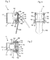
- a hanger 1 according to the invention is shown in perspective view. It is mounted on a tubular support 3 and held laterally by clamping. Two suspension points A are formed between the carrier 3 and the hanger 1. A suspension element 2 is suspended in each of these suspension points A. In the example shown, these are a hanging hook 2 or a hanging basket 2 '.
- the hanger 1 consists of a U-shaped spring element 11 as a clamping element and a closing part 15 which also partially surrounds this on its open side and is also U-shaped.
- the spring element 11 has a rear wall 111 and two free side walls 112, 113 adjoining it laterally at an angle.
- the two free side walls form an inwardly directed first clamping cheek 131 and second clamping cheek 132.
- the shape of the free side walls 112, 113 in the area of the clamping cheeks 131 and 132 is approximately adapted to a carrier 3 to be clamped, so that they are in the assembled, clamping state guarantee a good hold on the carrier.
- the free side walls 112, 113 form a closure cheek 114 on the outside, towards the free end.
- the closure cheeks 114 act in conjunction with the closing part 15 described below.
- the closing part 15 is also U-shaped and has a wall 151 and two free legs 152, 153 adjoining it at an angle. With its free legs 152, 153 it partially encompasses the open end of the spring element 11 and is pivotably attached to it.
- a securing bolt 16 penetrates both the closing part 15 and the spring element 11. It has terminal heads 162 which are widened at the end in order to be secured against being pushed out.
- the securing bolt 16 can also be a pierceable bolt with only one terminating head 162, which in the punctured state is secured at the end opposite the terminating head by means of a split pin or a nut.
- the spring element 11 and the closing part 15 together form an approximately rectangular cutout in the interior, in which the tubular support 3 is clamped.
- Spring element 11 and closing part 15 are dimensioned such that, when clamped to a carrier 3, at least between the carrier 3 and the rear wall 111 of the spring element 11, a recess 121 is formed.
- This recess 121 is used for receiving, that is, for inserting a hanging element 2, 2 ', for example a hanging hook or hanging angle.
- the spring element 11 is shown in FIG. 3 in cross-section in connection with the closing part 15 in the closed position and with the closing part 15 'in the open position.
- the rear wall 111 is cut and the free side wall 112 is drawn in a view from the inside.
- a first cutout 141 which serves as a means for the pivotable connection of the spring element 11 to the corresponding counterpart in the form of a pivoting cam 154 on the free leg 152 of the closing part 15, is clearly visible.
- the closing part 15 can be inserted in a simple manner from above into the spring element 11 and can be swiveled there.
- the closing part 15 can thus either be fixed to the spring element 11, for example with rivets, or releasably, but always pivotably.
- the closing part 15 compresses the spring element 11 somewhat, as described above.
- it is provided with a clamping rib 155 on the inside on both free legs 152, 153.
- the clamping ribs 155 project inward from the free legs 152, 153 and are thus in the closed position in direct contact with the associated locking cheeks 114.
- the closing part 15 as the closing part 15 ' is pivoted downwards outward about the pivoting cams 154 .
- the clamping ribs 155 are not in contact with the clamping cheeks 131, 132 and the spring element increases the distance between its free side walls 112 and 113 at least in the area of the closing cheeks 114.
- Each free side wall 112, 113 is provided with a first securing cutout 142 in the lower region, approximately opposite the first cutout 141.
- the safety cutout 142 is open against the end face of the free side wall 112, 113. From there it first leads somewhat inwards towards the rear wall 111 and then at a right angle downwards. It is intended to receive the safety bolt 16.
- In the closing part 15 is in each free Leg a second securing cutout 157. This has the shape of an elongated slot directed from top to bottom, which also serves to receive the securing bolt 16. Because of the slot-like design, the safety bolt can move up and down easily.
- the closing part 15 When the closing part 15 is swiveled in, or respectively when the hanger 1 is fastened, the securing bolt in the second securing cutouts 157 is now raised somewhat by hand so that it is finally pushed into the first securing cutouts 142.
- the closing part 15 clamps the free side walls 112, 113 somewhat together on the closing cheeks 114, as a result of which the hanger 11 is clamped onto a carrier 3.
- the securing bolt then moves downward through its own weight or pushed by hand within the first and second securing cutouts 142, 157. As a result, the securing bolt is moved into the downward-reaching part of the second securing cutouts 142 and thus prevents the closing part 15 from swiveling out unintentionally.
- the hanger is thus clamped and locked on the carrier 3.
- the closing element 15 is shown in FIG. 4 as seen from inside the spring element 11. It has an extension of its back plate 151 downward and thus forms an actuating handle 156.
- a pivot cam 154 is arranged on each free leg 152, 153 and points inward. It is obvious that this can also be a continuous pivot pin.
- the two free legs 152, 153 have a curvature that is slightly bent inwards. These curvatures lie opposite one another and form the clamping ribs 155.
- These clamping ribs 155 can of course also be designed as thickened points and, for example, simply applied as a short weld seam.
- the hanger 1 with the spring element 11 and the closing part 15 forms, when seen from above, approximately a rectangle which is filled approximately in the middle of the tubular carrier 3 in the closed state.
- a recess 121 and 122 are formed on both sides of the carrier 3 within the hanger 1, circumscribed by the walls thereof, as a diametrically opposed opening which runs freely from top to bottom.
- These recesses 121 and 122 serve to receive the Hanging elements 2, which can be easily inserted from above and are thus carried and held on the carrier 3 by means of the hanger 1.
- the hanger 1 can be provided with a fixed hook, for example. These can be made in one piece with the spring element 11 and or the closing part 15 or can be welded or glued thereto.
- hook-on hook elements 2 and welded or molded hooks as fasteners the range of uses of the hanger can be significantly expanded.
- the baskets described above can be hooked in and additionally, for example, tools can be detachably attached to the welded hooks, wherein these hooks can be specially shaped for the tool to be used.
Landscapes
- Engineering & Computer Science (AREA)
- General Engineering & Computer Science (AREA)
- Mechanical Engineering (AREA)
- Holders For Apparel And Elements Relating To Apparel (AREA)
Applications Claiming Priority (2)
| Application Number | Priority Date | Filing Date | Title |
|---|---|---|---|
| DE19615785 | 1996-04-20 | ||
| DE1996115785 DE19615785C1 (de) | 1996-04-20 | 1996-04-20 | Aufhänger für Einhängeelemente |
Publications (1)
| Publication Number | Publication Date |
|---|---|
| EP0802332A1 true EP0802332A1 (fr) | 1997-10-22 |
Family
ID=7791940
Family Applications (1)
| Application Number | Title | Priority Date | Filing Date |
|---|---|---|---|
| EP97810189A Withdrawn EP0802332A1 (fr) | 1996-04-20 | 1997-04-01 | Dispositif de support pour des articles |
Country Status (2)
| Country | Link |
|---|---|
| EP (1) | EP0802332A1 (fr) |
| DE (1) | DE19615785C1 (fr) |
Citations (5)
| Publication number | Priority date | Publication date | Assignee | Title |
|---|---|---|---|---|
| US3902931A (en) * | 1973-10-25 | 1975-09-02 | David K Danciger | Universal fastener and bracket |
| US4189810A (en) * | 1977-06-23 | 1980-02-26 | Societe Nouvelle Des Echafaudages Tubulaires Mills | Assembly elements, inter alia for scaffolding |
| US4616797A (en) * | 1984-08-13 | 1986-10-14 | Mina Manufacturing, Inc. | Adjustable support assembly |
| US4632221A (en) * | 1984-06-18 | 1986-12-30 | Stanford Joseph S | Bracing clamp for shoring structures |
| US4953819A (en) * | 1989-11-15 | 1990-09-04 | Davis Dale C | Adjustable support clamp apparatus and method |
Family Cites Families (2)
| Publication number | Priority date | Publication date | Assignee | Title |
|---|---|---|---|---|
| FR2480344A1 (fr) * | 1980-04-11 | 1981-10-16 | Reunis Sa Ateliers | Charniere d'articulation destinee a l'assemblage de deux panneaux, notamment pour articuler un panneau pivotant sur un panneau fixe |
| JPH066230Y2 (ja) * | 1989-04-07 | 1994-02-16 | 日産自動車株式会社 | 点火ケーブル用クランプ |
-
1996
- 1996-04-20 DE DE1996115785 patent/DE19615785C1/de not_active Expired - Fee Related
-
1997
- 1997-04-01 EP EP97810189A patent/EP0802332A1/fr not_active Withdrawn
Patent Citations (5)
| Publication number | Priority date | Publication date | Assignee | Title |
|---|---|---|---|---|
| US3902931A (en) * | 1973-10-25 | 1975-09-02 | David K Danciger | Universal fastener and bracket |
| US4189810A (en) * | 1977-06-23 | 1980-02-26 | Societe Nouvelle Des Echafaudages Tubulaires Mills | Assembly elements, inter alia for scaffolding |
| US4632221A (en) * | 1984-06-18 | 1986-12-30 | Stanford Joseph S | Bracing clamp for shoring structures |
| US4616797A (en) * | 1984-08-13 | 1986-10-14 | Mina Manufacturing, Inc. | Adjustable support assembly |
| US4953819A (en) * | 1989-11-15 | 1990-09-04 | Davis Dale C | Adjustable support clamp apparatus and method |
Also Published As
| Publication number | Publication date |
|---|---|
| DE19615785C1 (de) | 1998-02-05 |
Similar Documents
| Publication | Publication Date | Title |
|---|---|---|
| EP1312287A1 (fr) | Dispositif de suspension comprenant un profilé destiné à être monté verticalement et une console pouvant être accrochée à ce profilé | |
| EP0352515A2 (fr) | Diable pliant à deux roues | |
| EP0539875A1 (fr) | Dispositif de verrouillage rapide | |
| DE19615785C1 (de) | Aufhänger für Einhängeelemente | |
| DE8409725U1 (de) | Gleitschutzvorrichtung fuer fahrzeugreifen | |
| DE10145416A1 (de) | Vorrichtung zum Sichern von Ladegut auf der Ladefläche eines Fahrzeuges | |
| DE19900154A1 (de) | Klammer | |
| DE29607205U1 (de) | Aufhänger für Einhängeelemente | |
| DE19502225C2 (de) | Anhängevorrichtung zum Anhängen wenigstens einer Schaltafel an ein Hebezeug | |
| DE68919974T2 (de) | Gestell zur Abdeckung eines Lkw-Aufbaues. | |
| EP0280651A1 (fr) | Support à tous usages | |
| DE3315335A1 (de) | Dachtraeger fuer kraftfahrzeuge | |
| DE19860213B4 (de) | Hordenwagen | |
| DE3611445C2 (fr) | ||
| DE4423373C2 (de) | Einrichtung zum Befestigen von Taschen, insbesondere an Zweirädern | |
| EP1712686B1 (fr) | Elément de connection, en particulier pour treillis d'armature | |
| DE60305161T2 (de) | Gepäckträger für ein fahrzeug | |
| DE29622467U1 (de) | Sieb, insbesondere Haushaltssieb | |
| EP0881150A1 (fr) | Support pour sacs de ramassage d'ordures | |
| DE2403771A1 (de) | Schnellspannabhaenger fuer die tragschienen von unterdecken o.dgl. | |
| DE202004000123U1 (de) | Kabeltragvorrichtung | |
| DE8415717U1 (de) | Heckgepäckträger für Kraftfahrzeuge | |
| DE4332243B4 (de) | Fahrzeuggepäckbox, insbesondere Dachkoffer für Kraftfahrzeuge | |
| DE29501062U1 (de) | Anhängevorrichtung zum Anhängen wenigstens einer Schaltafel an ein Hebezeug | |
| DE3322217C2 (de) | Selbstfanghalsrahmen für Tiere |
Legal Events
| Date | Code | Title | Description |
|---|---|---|---|
| PUAI | Public reference made under article 153(3) epc to a published international application that has entered the european phase |
Free format text: ORIGINAL CODE: 0009012 |
|
| AK | Designated contracting states |
Kind code of ref document: A1 Designated state(s): AT CH FI FR GB IT LI NL SE |
|
| 17P | Request for examination filed |
Effective date: 19980205 |
|
| GRAG | Despatch of communication of intention to grant |
Free format text: ORIGINAL CODE: EPIDOS AGRA |
|
| 17Q | First examination report despatched |
Effective date: 19980427 |
|
| GRAG | Despatch of communication of intention to grant |
Free format text: ORIGINAL CODE: EPIDOS AGRA |
|
| GRAH | Despatch of communication of intention to grant a patent |
Free format text: ORIGINAL CODE: EPIDOS IGRA |
|
| STAA | Information on the status of an ep patent application or granted ep patent |
Free format text: STATUS: THE APPLICATION IS DEEMED TO BE WITHDRAWN |
|
| 18D | Application deemed to be withdrawn |
Effective date: 19981118 |