EP0802004B1 - Verfahren zum Füllen von Kernen mit Formsand - Google Patents
Verfahren zum Füllen von Kernen mit Formsand Download PDFInfo
- Publication number
- EP0802004B1 EP0802004B1 EP97106020A EP97106020A EP0802004B1 EP 0802004 B1 EP0802004 B1 EP 0802004B1 EP 97106020 A EP97106020 A EP 97106020A EP 97106020 A EP97106020 A EP 97106020A EP 0802004 B1 EP0802004 B1 EP 0802004B1
- Authority
- EP
- European Patent Office
- Prior art keywords
- sand
- core
- cavity
- molding
- filling
- Prior art date
- Legal status (The legal status is an assumption and is not a legal conclusion. Google has not performed a legal analysis and makes no representation as to the accuracy of the status listed.)
- Expired - Lifetime
Links
- 238000000034 method Methods 0.000 title claims description 13
- 239000003110 molding sand Substances 0.000 title claims description 8
- 239000004576 sand Substances 0.000 claims description 57
- 238000000465 moulding Methods 0.000 claims description 19
- 238000007664 blowing Methods 0.000 claims description 11
- 238000005266 casting Methods 0.000 description 1
- 239000003795 chemical substances by application Substances 0.000 description 1
- 238000004140 cleaning Methods 0.000 description 1
- 239000002245 particle Substances 0.000 description 1
Images

Classifications
-
- B—PERFORMING OPERATIONS; TRANSPORTING
- B22—CASTING; POWDER METALLURGY
- B22C—FOUNDRY MOULDING
- B22C5/00—Machines or devices specially designed for dressing or handling the mould material so far as specially adapted for that purpose
- B22C5/12—Machines or devices specially designed for dressing or handling the mould material so far as specially adapted for that purpose for filling flasks
-
- B—PERFORMING OPERATIONS; TRANSPORTING
- B22—CASTING; POWDER METALLURGY
- B22C—FOUNDRY MOULDING
- B22C7/00—Patterns; Manufacture thereof so far as not provided for in other classes
- B22C7/06—Core boxes
- B22C7/065—Venting means
-
- B—PERFORMING OPERATIONS; TRANSPORTING
- B22—CASTING; POWDER METALLURGY
- B22C—FOUNDRY MOULDING
- B22C15/00—Moulding machines characterised by the compacting mechanism; Accessories therefor
- B22C15/23—Compacting by gas pressure or vacuum
-
- B—PERFORMING OPERATIONS; TRANSPORTING
- B22—CASTING; POWDER METALLURGY
- B22C—FOUNDRY MOULDING
- B22C15/00—Moulding machines characterised by the compacting mechanism; Accessories therefor
- B22C15/23—Compacting by gas pressure or vacuum
- B22C15/24—Compacting by gas pressure or vacuum involving blowing devices in which the mould material is supplied in the form of loose particles
Definitions
- This invention relates to a method of filling a core box with sand for molding the core so that it is uniformly filled with highly-compacted sand.
- a blowing method wherein sand for molding a core is blown along with compressed air, is used conventionally to fill a core box with the molding sand.
- Using the blowing method necessitates troublesome trial-and-error operations to make many ventholes in the core box.
- the blowing method has drawbacks in that since in the method a blow head, which has a built-in sand cylinder, is used, the structure of the blow head is complex, and necessitates troublesome work for its cleaning.
- a core shooter for filling a core box or mold flask with molding sand comprises surrounding the core box by a chamber hood between a blowing cartridge and a work table on which the core box is placed, and a tight seal on such elements.
- a chamber hood fitted with a connection to a vacuum pump, prior to the opening of a valve which causes the blowing cartridge to discharge casting sand into the core box, inside the latter, through conventional ventholes air is expelled through the surrounding chamber.
- a vacuum is provided which considerably enhances the discharge of the blowing cartridge, allowing the latter to be effected even in highly complex or sizable cores, without having to use special blowing nozzles or heads to reach all remote areas of the core box.
- the blowing method has still more problems in that if the cavity of a core has an oblong or complex shape, not all parts of the cavity can be filled uniformly with highly compacted sand for molding the core. This results in irregularities in the density of the compacted sand. There is also a problem in that if a high pressure is used to improve the effects of compacting the sand, the speed of the rushing sand particles increases so that separatory agents on the inside of a core box tend to come off. This generates stained sand.
- This invention is made by considering the above problems. Its purpose is to provide a method that can uniformly fill every part of the cavity of a core with highly compacted sand for molding the core without the need of operations to make many ventholes in the core box even when the cavity has an oblong or complex shape.
- one method of this invention is characterized by the steps of preparatorily filling a core cavity with the sand for molding the core by blowing the sand into the core cavity after a blow head, into which the sand for molding the core has been thrown, is press-contacted with the upper surface of a core box having the core cavity and a sand-supply inlet, impulsively press-filling the parts of the core cavity, which are the farthest from the inlet, by abruptly introducing compressed air via a plurality of openings provided over the length of the core cavity at appropriate distances therebetween, and repeating the steps of impulsively press-filling the parts of the cavity, by sequentially reducing the number of the openings, via which compressed air is to be introduced, from the farthest to the nearest positions from the inlet.
- Another method of this invention is characterized by the steps of preparatorily filling a cavity with sand for molding a core by depressurizing the cavity so that the sand is absorbed, after a blow head, into which the sand for molding the core has been thrown, is press-contacted with the upper surface of a core box having the core cavity and a supply inlet for the sand, impulsively press-filling the parts of the cavity that are the farthest from the inlet by abruptly introducing compressed air into a plurality of openings provided over the length of the cavity at appropriate distances therebetween, after the cavity and blow head are vacuum-depressurized, and repeating the step of impulsively press-filling the parts of the cavity, by sequentially changing the parts to be pressed from the farthest to the nearest positions from the inlet.
- a core box 1 is constituted by an upper mold 1A and a lower mold 1B so that the core is separabale horizontally along a boundary therebetween. It has in its inside a laterally oblong core cavity 2 having a plurality of uneven surfaces in the up-and-down direction.
- a supply inlet 3 for sand is provided so that it upwardly passes through the center of the upper part of the core cavity 2.
- a plurality of ventholes 4-8 are provided at proper intervals therebetween in the bottom parts of the core cavity 2 so that they downwardly pass therethrough. Vent plugs 9 are engaged with respective ventholes 4-8.
- a blow head 11 is press-contacted with the upper part of the core box 1.
- a supply inlet 13 for sand which is opened or closed by an opening-and-closing lid 12, is provided on the upper wall of the blow head 11.
- a supply-discharge hole 14 is provided in the upper part of the blow head 11.
- the supply-discharge hole 14 communicates with a source of compressed air (not shown) via main piping 16 and a closing valve 17.
- Three branched pipes 18-20 are provided at positions downstream from the closing valve 17 in the main piping 16.
- the ends of the branched pipe 18 communicate with ventholes 4 and 8, the ends of the branched pipe 19 communicate with ventholes 5 and 7, and the end of the branched pipe 20 communicates with a venthole 6.
- the branched pipes 18-20 are equipped with closing valves 18A-20A.
- a suction pipe 22, leading to a vacuum pump 21, communicates via a closing valve 22A with the main piping 16.
- the main piping 16 also communicates via closing valves 23A-25A with branched suction pipes 23-25, which lead to the vacuum pump 21, and which are disposed in the branched pipes 18-20 at positions downstream of the closing valves 18A-20A.
- closing valves 23A-25A With branched suction pipes 23-25, which lead to the vacuum pump 21, and which are disposed in the branched pipes 18-20 at positions downstream of the closing valves 18A-20A.
- S molding sand is denoted by S.
- the blow head 11 supplied with sand for molding the core, is press-contacted with the thus-structured core box 1.
- a blow hole 10 of the head 11 communicates with the sand-supply inlet 3.
- the molding sand for the core in the blow head 11 is absorbed into the core cavity 2 to fill it preparatorily (as in Fig. 1) after the core cavity 2 is depressurized by opening the closing valves 23A-25A (while the other valves are closed) through the absorbtive action of the vacuum pump 21. In this state not all of the corners of the core cavity are fully filled with highly-compacted sand S by just the absorbtive actions.
- the closing valves 22A-25A are then opened so that the core cavity 2 and blow head 11 are depressurized.
- the closing valves 22A-25A are closed, and simultaneously with this the valves 17, 19A, and 20A are opened so that compressed air is supplied into both the blow head 11 and the core cavity 2, via the ventholes 5, 6, and 7.
- the next farthest parts from the sand-supply inlet 3 (those positions that are farther away from the ventholes 5 and 7) of the core cavity 2 are filled with highly-compacted sand S.
- the central parts of the cavity 2 around the venthole 6 are also filled with highly compacted sand S by compressed air supplied via just the closing valves 17 and 20A.
- the sand S for the core which has been preparatorily drawn into the core cavity 2, is uniformly and highly compacted all over the cavity. That is, the sand S is sequentially compacted, from the sand at the farthest positions to the sand at the nearest positions, from the sand-supply inlet 3, by sequentially changing the positions for supplying compressed air to sequentially pressurize the sand S.
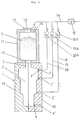
- a core box 1 is constituted by a left mold 1A and a right mold 1B so that the core is separabale vertically along the boundary therebetween. It has in its inside a vertically oblong core cavity 2 having a plurality of uneven surfaces in the right-and-left directions.
- a supply inlet 3 for sand is provided so that it upwardly passes through the center of the upper part of the core cavity 2.
- a plurality of ventholes 4'-7' are provided at proper intervals therebetween in the side parts of the core cavity 2 so that they outwardly pass therethrough. Vent plugs 9 are engaged with respective ventholes 4'-7'.
- a blow head 11 is press-contacted with the upper part of the core box 1.
- a sand-supply inlet 13, which is opened or closed by an opening-and-closing lid 12, is provided on the upper wall of the blow head 11.
- An air-supply hole 14 is provided in the upper part of the blow head 11.
- the air-supply hole 14 communicates with a source of compressed air (not shown) via main piping 16 and a closing valve 17.
- Three branched pipes 18-20 are provided at positions downstream from the closing valve 17 in the main piping 16.
- the end of the branched pipe 18 communicates with a venthole 5'
- the end of the branched pipe 19 communicates with a venthole 6'
- the end of the branched pipe 20 communicates with a venthole 7'.
- the branched pipes 18-20 are equipped with directional control valves 18A-20A. These control valves are for switching the connections between two directions. One is for connecting the main piping 16 to the ventholes 5'-7' and the other is for connecting the ventholes 5'-7' to the atmosphere.
- S is denoted by S.
- the blow head 11 supplied with sand for molding the core, is press-contacted with the thus-structured core box 1, with a blow hole 9 of the head 11 communicating with the sand-supply inlet 3.
- the directional control valves 18A-20A are then connected to the atmosphere, and the closing valve 17 is opened so that the molding sand S in the blow head 11 is blown into the core cavity 2 to fill it preparatorily. After that the closing valve 17 is closed. In this state not all the corners of the core cavity 2 are fully filled with highly-compacted sand S by just the blowing actions.
- the closing valve 17 is opened to abruptly supply compressed air via the blow head 11 and ventholes 5'-7' into the core cavity 2, so that the upper parts of the sand S in the blow head 11 are press-pushed, and so that the farthest positions (below the venthole 5') in the cavity 2 from the sand-supply inlet 3 are filled with highly-compacted sand S. After that the closing valve 17 is closed.
- the closing valve 18A After the directional control valve 18A is switched to the direction wherein the venthole 5' is connected to the atmosphere, the closing valve is opened so that compressed air is supplied into the blow head 11, and into the core cavity 2 via the ventholes 6' and 7'.
- the second farthest parts (those positions below the venthole 6') of the core cavity 2 from the sand-supply inlet 3 are filled with highly-compacted sand S.
- the parts of the cavity 2 around the venthole 7' are also filled with highly compacted sand S by supplying compressed air via just the closing valve 20A.
- the sand S for molding the core which has been preparatorily drawn into the core cavity 2, is uniformly and highly compacted all over the cavity.
- the sand S is sequentially compacted, from the sand at the farthest positions to the sand at the nearest positions from the sand-supply inlet 3, by sequentially changing the positions for supplying compressed air to sequentially pressurize the sand S.
Landscapes
- Engineering & Computer Science (AREA)
- Mechanical Engineering (AREA)
- Molds, Cores, And Manufacturing Methods Thereof (AREA)
- Casting Devices For Molds (AREA)
Claims (3)
- Ein Verfahren zum Füllen eines Kerns mit Formsand, mit den folgenden Schritten:Vorbereitendes Füllen eines Kernhohlraums (2) mit dem Sand zum Formen des Kerns durch Blasen des Sandes in den Kernhohlraum (2), nachdem ein Blaskopf (11), in welchen der Sand zum Formen des Kerns eingebracht wurde, in Druckverbindung mit der oberen Oberfläche eines Kernkastens (1) gebracht wurde, der den Kernhohlraum (2) und einen Sandzufuhreinlaß (3) aufweist;Pressverfüllen derjenigen Teile des Kernhohlraums (2), welche am weitesten von dem Einlaß (3) entfernt sind, durch abruptes Einbringen von Druckluft über eine Mehrzahl von Öffnungen (4, 5, 6, 7, 8), welche über die Länge des Kernhohlraums (2) mit geeigneten Abständen zwischen sich angeordnet sind; undWiederholen der Schritte des Pressverfüllens der Teile des Hohlraums (2) durch aufeinanderfolgendes Verringern der Anzahl der Öffnungen (4, 5, 6, 7, 8), über welche Druckluft eingebracht wird von den vom Einlaß (3) am weitesten entfernten bis zu den nächsten Positionen.
- Verfahren nach Anspruch 1, wobei der Schritt des Füllens des Kernhohlraums (2) durch Drucklosmachen des Hohlraums (2) durchgeführt wird, so daß der Sand eingesaugt wird.
- Verfahren nach Anspruch 1, wobei der Schritt des Pressverfahrens des Kernhohlraums (2) durchgeführt wird, nachdem der Hohlraum und der Blaskopf (10) vakuum-drucklos gemacht wurden.
Applications Claiming Priority (6)
| Application Number | Priority Date | Filing Date | Title |
|---|---|---|---|
| JP122496/96 | 1996-04-19 | ||
| JP12249696 | 1996-04-19 | ||
| JP12249696A JP3235714B2 (ja) | 1996-04-19 | 1996-04-19 | 中子砂の充填方法 |
| JP15313096A JP3269545B2 (ja) | 1996-05-24 | 1996-05-24 | 中子砂の充填方法 |
| JP15313096 | 1996-05-24 | ||
| JP153130/96 | 1996-05-24 |
Publications (3)
| Publication Number | Publication Date |
|---|---|
| EP0802004A2 EP0802004A2 (de) | 1997-10-22 |
| EP0802004A3 EP0802004A3 (de) | 1997-11-12 |
| EP0802004B1 true EP0802004B1 (de) | 1999-09-15 |
Family
ID=26459602
Family Applications (1)
| Application Number | Title | Priority Date | Filing Date |
|---|---|---|---|
| EP97106020A Expired - Lifetime EP0802004B1 (de) | 1996-04-19 | 1997-04-11 | Verfahren zum Füllen von Kernen mit Formsand |
Country Status (7)
| Country | Link |
|---|---|
| US (1) | US5850867A (de) |
| EP (1) | EP0802004B1 (de) |
| KR (1) | KR970073793A (de) |
| CN (1) | CN1065789C (de) |
| DE (1) | DE69700511T2 (de) |
| ID (1) | ID18774A (de) |
| TW (1) | TW367275B (de) |
Families Citing this family (5)
| Publication number | Priority date | Publication date | Assignee | Title |
|---|---|---|---|---|
| DE19755755A1 (de) * | 1997-12-16 | 1999-06-24 | Wagner Heinrich Sinto Masch | Verfahren und Vorrichtung zum Verdichten von Formsand |
| DE102005043754B4 (de) * | 2005-09-13 | 2008-09-25 | Minelco Gmbh | Verfahren und Vorrichtung zur Herstellung von Kernformlingen für die Gießereitechnik |
| JP5062540B2 (ja) * | 2010-01-13 | 2012-10-31 | 新東工業株式会社 | 鋳型造型機におけるサンドタンクの給排気装置及び給排気方法 |
| CN102209448B (zh) * | 2010-03-29 | 2015-03-25 | 奥托立夫开发公司 | 电路板保护盒及其安装方法 |
| PL3307456T3 (pl) * | 2015-06-12 | 2019-12-31 | Disa Industries A/S | Urządzenie do odlewania piaskowego oraz sposób wytwarzania form |
Family Cites Families (3)
| Publication number | Priority date | Publication date | Assignee | Title |
|---|---|---|---|---|
| ES2012702A6 (es) * | 1989-04-06 | 1990-04-01 | Erana Agustin Arana | Mejoras en maquinas de moldeo de cajas de arena por impacto de aire. |
| ES2053382B1 (es) * | 1992-03-16 | 1996-08-16 | Erana Agustin Arana | Mejoras en disparadoras de machos para proceso autofraguante con sistema de vacio. |
| JP3083042B2 (ja) * | 1994-05-12 | 2000-09-04 | 新東工業株式会社 | 鋳型造型方法 |
-
1997
- 1997-04-10 TW TW086104579A patent/TW367275B/zh active
- 1997-04-11 EP EP97106020A patent/EP0802004B1/de not_active Expired - Lifetime
- 1997-04-11 DE DE69700511T patent/DE69700511T2/de not_active Expired - Fee Related
- 1997-04-14 US US08/843,166 patent/US5850867A/en not_active Expired - Fee Related
- 1997-04-17 ID IDP971281A patent/ID18774A/id unknown
- 1997-04-18 CN CN97109557A patent/CN1065789C/zh not_active Expired - Fee Related
- 1997-04-18 KR KR1019970014308A patent/KR970073793A/ko not_active Withdrawn
Also Published As
| Publication number | Publication date |
|---|---|
| CN1171310A (zh) | 1998-01-28 |
| ID18774A (id) | 1998-05-07 |
| DE69700511D1 (de) | 1999-10-21 |
| EP0802004A2 (de) | 1997-10-22 |
| US5850867A (en) | 1998-12-22 |
| TW367275B (en) | 1999-08-21 |
| EP0802004A3 (de) | 1997-11-12 |
| CN1065789C (zh) | 2001-05-16 |
| DE69700511T2 (de) | 2000-05-04 |
| KR970073793A (ko) | 1997-12-10 |
Similar Documents
| Publication | Publication Date | Title |
|---|---|---|
| KR101652883B1 (ko) | 주형 조형기 | |
| EP1184106A1 (de) | Verfahren und vorrichtung zum befüllen mit giessereisand | |
| KR100196981B1 (ko) | 주형 조형기 | |
| EP0802004B1 (de) | Verfahren zum Füllen von Kernen mit Formsand | |
| CN1007793B (zh) | 制造无砂箱铸型的方法和设备 | |
| US5715885A (en) | Apparatus and method for cleaning core box vents | |
| EA008468B1 (ru) | Способ и устройство разливки и отливка, полученная в процессе вакуумного формования | |
| JP4379795B2 (ja) | 鋳物砂の充填方法 | |
| CN107872992B (zh) | 砂模机和制造模具的方法 | |
| JP3161290B2 (ja) | 中子造型装置 | |
| JP4099744B2 (ja) | 鋳物砂の鋳枠への吹込み充填装置 | |
| CN1007792B (zh) | 铸模零件的生产方法 | |
| EP0844036B1 (de) | Formoberkasten mit Bohrung zum Begasen von Kernen | |
| US6253827B1 (en) | Method of compressing molding sand using independently controlled gas guiding pipes | |
| JPH0648578A (ja) | コアシューター装置 | |
| JPH06277800A (ja) | 吹込み式鋳型造型方法およびその装置 | |
| US20010009184A1 (en) | Blow molding machine | |
| US20080169079A1 (en) | Sand-introducing-type sand molding machine | |
| JPH08132180A (ja) | 鋳型造型方法およびその装置 | |
| JP2772869B2 (ja) | 鋳型造型方法 | |
| JP2003340551A (ja) | 無枠式鋳型の造型方法及び無枠式鋳型造型機 | |
| JP3410434B2 (ja) | 鋳物砂の充填方法及びその装置 | |
| JPS6317560Y2 (de) | ||
| JP3518969B2 (ja) | 鋳型中子の造型方法および造型装置 | |
| JP3007821B2 (ja) | 鋳造用中子造型装置 |
Legal Events
| Date | Code | Title | Description |
|---|---|---|---|
| PUAI | Public reference made under article 153(3) epc to a published international application that has entered the european phase |
Free format text: ORIGINAL CODE: 0009012 |
|
| PUAL | Search report despatched |
Free format text: ORIGINAL CODE: 0009013 |
|
| AK | Designated contracting states |
Kind code of ref document: A2 Designated state(s): CH DE FR GB LI |
|
| AK | Designated contracting states |
Kind code of ref document: A3 Designated state(s): CH DE FR GB LI |
|
| 17P | Request for examination filed |
Effective date: 19980205 |
|
| 17Q | First examination report despatched |
Effective date: 19980227 |
|
| GRAG | Despatch of communication of intention to grant |
Free format text: ORIGINAL CODE: EPIDOS AGRA |
|
| GRAG | Despatch of communication of intention to grant |
Free format text: ORIGINAL CODE: EPIDOS AGRA |
|
| GRAH | Despatch of communication of intention to grant a patent |
Free format text: ORIGINAL CODE: EPIDOS IGRA |
|
| GRAH | Despatch of communication of intention to grant a patent |
Free format text: ORIGINAL CODE: EPIDOS IGRA |
|
| GRAA | (expected) grant |
Free format text: ORIGINAL CODE: 0009210 |
|
| AK | Designated contracting states |
Kind code of ref document: B1 Designated state(s): CH DE FR GB LI |
|
| PG25 | Lapsed in a contracting state [announced via postgrant information from national office to epo] |
Ref country code: LI Free format text: LAPSE BECAUSE OF FAILURE TO SUBMIT A TRANSLATION OF THE DESCRIPTION OR TO PAY THE FEE WITHIN THE PRESCRIBED TIME-LIMIT Effective date: 19990915 Ref country code: FR Free format text: LAPSE BECAUSE OF FAILURE TO SUBMIT A TRANSLATION OF THE DESCRIPTION OR TO PAY THE FEE WITHIN THE PRESCRIBED TIME-LIMIT Effective date: 19990915 Ref country code: CH Free format text: LAPSE BECAUSE OF FAILURE TO SUBMIT A TRANSLATION OF THE DESCRIPTION OR TO PAY THE FEE WITHIN THE PRESCRIBED TIME-LIMIT Effective date: 19990915 |
|
| REG | Reference to a national code |
Ref country code: CH Ref legal event code: EP |
|
| REF | Corresponds to: |
Ref document number: 69700511 Country of ref document: DE Date of ref document: 19991021 |
|
| EN | Fr: translation not filed | ||
| REG | Reference to a national code |
Ref country code: CH Ref legal event code: PL |
|
| PLBE | No opposition filed within time limit |
Free format text: ORIGINAL CODE: 0009261 |
|
| STAA | Information on the status of an ep patent application or granted ep patent |
Free format text: STATUS: NO OPPOSITION FILED WITHIN TIME LIMIT |
|
| 26N | No opposition filed | ||
| PGFP | Annual fee paid to national office [announced via postgrant information from national office to epo] |
Ref country code: GB Payment date: 20010330 Year of fee payment: 5 |
|
| PGFP | Annual fee paid to national office [announced via postgrant information from national office to epo] |
Ref country code: DE Payment date: 20010423 Year of fee payment: 5 |
|
| REG | Reference to a national code |
Ref country code: GB Ref legal event code: IF02 |
|
| PG25 | Lapsed in a contracting state [announced via postgrant information from national office to epo] |
Ref country code: GB Free format text: LAPSE BECAUSE OF NON-PAYMENT OF DUE FEES Effective date: 20020411 |
|
| PG25 | Lapsed in a contracting state [announced via postgrant information from national office to epo] |
Ref country code: DE Free format text: LAPSE BECAUSE OF NON-PAYMENT OF DUE FEES Effective date: 20021101 |
|
| GBPC | Gb: european patent ceased through non-payment of renewal fee |
Effective date: 20020411 |