EP0801498A2 - Appareil d'enregistrement et/ou reproduction digital d'un signal vidéo - Google Patents
Appareil d'enregistrement et/ou reproduction digital d'un signal vidéo Download PDFInfo
- Publication number
- EP0801498A2 EP0801498A2 EP97110447A EP97110447A EP0801498A2 EP 0801498 A2 EP0801498 A2 EP 0801498A2 EP 97110447 A EP97110447 A EP 97110447A EP 97110447 A EP97110447 A EP 97110447A EP 0801498 A2 EP0801498 A2 EP 0801498A2
- Authority
- EP
- European Patent Office
- Prior art keywords
- recording
- block
- blocks
- small
- fixed length
- Prior art date
- Legal status (The legal status is an assumption and is not a legal conclusion. Google has not performed a legal analysis and makes no representation as to the accuracy of the status listed.)
- Granted
Links
- 230000008707 rearrangement Effects 0.000 claims description 11
- 230000009467 reduction Effects 0.000 abstract description 31
- 238000000034 method Methods 0.000 description 44
- 230000008569 process Effects 0.000 description 14
- 230000000007 visual effect Effects 0.000 description 10
- 230000000903 blocking effect Effects 0.000 description 8
- 238000000354 decomposition reaction Methods 0.000 description 6
- 230000000694 effects Effects 0.000 description 6
- IUVCFHHAEHNCFT-INIZCTEOSA-N 2-[(1s)-1-[4-amino-3-(3-fluoro-4-propan-2-yloxyphenyl)pyrazolo[3,4-d]pyrimidin-1-yl]ethyl]-6-fluoro-3-(3-fluorophenyl)chromen-4-one Chemical compound C1=C(F)C(OC(C)C)=CC=C1C(C1=C(N)N=CN=C11)=NN1[C@@H](C)C1=C(C=2C=C(F)C=CC=2)C(=O)C2=CC(F)=CC=C2O1 IUVCFHHAEHNCFT-INIZCTEOSA-N 0.000 description 5
- 230000008901 benefit Effects 0.000 description 5
- 238000010586 diagram Methods 0.000 description 5
- 238000005457 optimization Methods 0.000 description 4
- 238000001514 detection method Methods 0.000 description 3
- 230000001174 ascending effect Effects 0.000 description 2
- 230000015556 catabolic process Effects 0.000 description 1
- 238000006243 chemical reaction Methods 0.000 description 1
- 238000006731 degradation reaction Methods 0.000 description 1
- 230000001737 promoting effect Effects 0.000 description 1
- 230000009466 transformation Effects 0.000 description 1
Images


Classifications
-
- G—PHYSICS
- G11—INFORMATION STORAGE
- G11B—INFORMATION STORAGE BASED ON RELATIVE MOVEMENT BETWEEN RECORD CARRIER AND TRANSDUCER
- G11B5/00—Recording by magnetisation or demagnetisation of a record carrier; Reproducing by magnetic means; Record carriers therefor
- G11B5/02—Recording, reproducing, or erasing methods; Read, write or erase circuits therefor
-
- H—ELECTRICITY
- H04—ELECTRIC COMMUNICATION TECHNIQUE
- H04N—PICTORIAL COMMUNICATION, e.g. TELEVISION
- H04N5/00—Details of television systems
- H04N5/76—Television signal recording
- H04N5/91—Television signal processing therefor
- H04N5/92—Transformation of the television signal for recording, e.g. modulation, frequency changing; Inverse transformation for playback
- H04N5/926—Transformation of the television signal for recording, e.g. modulation, frequency changing; Inverse transformation for playback by pulse code modulation
- H04N5/9261—Transformation of the television signal for recording, e.g. modulation, frequency changing; Inverse transformation for playback by pulse code modulation involving data reduction
- H04N5/9264—Transformation of the television signal for recording, e.g. modulation, frequency changing; Inverse transformation for playback by pulse code modulation involving data reduction using transform coding
-
- G—PHYSICS
- G11—INFORMATION STORAGE
- G11B—INFORMATION STORAGE BASED ON RELATIVE MOVEMENT BETWEEN RECORD CARRIER AND TRANSDUCER
- G11B20/00—Signal processing not specific to the method of recording or reproducing; Circuits therefor
- G11B20/10—Digital recording or reproducing
- G11B20/18—Error detection or correction; Testing, e.g. of drop-outs
- G11B20/1806—Pulse code modulation systems for audio signals
- G11B20/1809—Pulse code modulation systems for audio signals by interleaving
-
- H—ELECTRICITY
- H04—ELECTRIC COMMUNICATION TECHNIQUE
- H04N—PICTORIAL COMMUNICATION, e.g. TELEVISION
- H04N19/00—Methods or arrangements for coding, decoding, compressing or decompressing digital video signals
- H04N19/10—Methods or arrangements for coding, decoding, compressing or decompressing digital video signals using adaptive coding
- H04N19/102—Methods or arrangements for coding, decoding, compressing or decompressing digital video signals using adaptive coding characterised by the element, parameter or selection affected or controlled by the adaptive coding
- H04N19/115—Selection of the code volume for a coding unit prior to coding
-
- H—ELECTRICITY
- H04—ELECTRIC COMMUNICATION TECHNIQUE
- H04N—PICTORIAL COMMUNICATION, e.g. TELEVISION
- H04N19/00—Methods or arrangements for coding, decoding, compressing or decompressing digital video signals
- H04N19/10—Methods or arrangements for coding, decoding, compressing or decompressing digital video signals using adaptive coding
- H04N19/134—Methods or arrangements for coding, decoding, compressing or decompressing digital video signals using adaptive coding characterised by the element, parameter or criterion affecting or controlling the adaptive coding
- H04N19/146—Data rate or code amount at the encoder output
- H04N19/147—Data rate or code amount at the encoder output according to rate distortion criteria
-
- H—ELECTRICITY
- H04—ELECTRIC COMMUNICATION TECHNIQUE
- H04N—PICTORIAL COMMUNICATION, e.g. TELEVISION
- H04N19/00—Methods or arrangements for coding, decoding, compressing or decompressing digital video signals
- H04N19/10—Methods or arrangements for coding, decoding, compressing or decompressing digital video signals using adaptive coding
- H04N19/134—Methods or arrangements for coding, decoding, compressing or decompressing digital video signals using adaptive coding characterised by the element, parameter or criterion affecting or controlling the adaptive coding
- H04N19/154—Measured or subjectively estimated visual quality after decoding, e.g. measurement of distortion
-
- H—ELECTRICITY
- H04—ELECTRIC COMMUNICATION TECHNIQUE
- H04N—PICTORIAL COMMUNICATION, e.g. TELEVISION
- H04N19/00—Methods or arrangements for coding, decoding, compressing or decompressing digital video signals
- H04N19/10—Methods or arrangements for coding, decoding, compressing or decompressing digital video signals using adaptive coding
- H04N19/169—Methods or arrangements for coding, decoding, compressing or decompressing digital video signals using adaptive coding characterised by the coding unit, i.e. the structural portion or semantic portion of the video signal being the object or the subject of the adaptive coding
- H04N19/17—Methods or arrangements for coding, decoding, compressing or decompressing digital video signals using adaptive coding characterised by the coding unit, i.e. the structural portion or semantic portion of the video signal being the object or the subject of the adaptive coding the unit being an image region, e.g. an object
- H04N19/176—Methods or arrangements for coding, decoding, compressing or decompressing digital video signals using adaptive coding characterised by the coding unit, i.e. the structural portion or semantic portion of the video signal being the object or the subject of the adaptive coding the unit being an image region, e.g. an object the region being a block, e.g. a macroblock
-
- H—ELECTRICITY
- H04—ELECTRIC COMMUNICATION TECHNIQUE
- H04N—PICTORIAL COMMUNICATION, e.g. TELEVISION
- H04N19/00—Methods or arrangements for coding, decoding, compressing or decompressing digital video signals
- H04N19/10—Methods or arrangements for coding, decoding, compressing or decompressing digital video signals using adaptive coding
- H04N19/169—Methods or arrangements for coding, decoding, compressing or decompressing digital video signals using adaptive coding characterised by the coding unit, i.e. the structural portion or semantic portion of the video signal being the object or the subject of the adaptive coding
- H04N19/179—Methods or arrangements for coding, decoding, compressing or decompressing digital video signals using adaptive coding characterised by the coding unit, i.e. the structural portion or semantic portion of the video signal being the object or the subject of the adaptive coding the unit being a scene or a shot
-
- H—ELECTRICITY
- H04—ELECTRIC COMMUNICATION TECHNIQUE
- H04N—PICTORIAL COMMUNICATION, e.g. TELEVISION
- H04N19/00—Methods or arrangements for coding, decoding, compressing or decompressing digital video signals
- H04N19/42—Methods or arrangements for coding, decoding, compressing or decompressing digital video signals characterised by implementation details or hardware specially adapted for video compression or decompression, e.g. dedicated software implementation
-
- H—ELECTRICITY
- H04—ELECTRIC COMMUNICATION TECHNIQUE
- H04N—PICTORIAL COMMUNICATION, e.g. TELEVISION
- H04N19/00—Methods or arrangements for coding, decoding, compressing or decompressing digital video signals
- H04N19/60—Methods or arrangements for coding, decoding, compressing or decompressing digital video signals using transform coding
-
- H—ELECTRICITY
- H04—ELECTRIC COMMUNICATION TECHNIQUE
- H04N—PICTORIAL COMMUNICATION, e.g. TELEVISION
- H04N19/00—Methods or arrangements for coding, decoding, compressing or decompressing digital video signals
- H04N19/85—Methods or arrangements for coding, decoding, compressing or decompressing digital video signals using pre-processing or post-processing specially adapted for video compression
- H04N19/88—Methods or arrangements for coding, decoding, compressing or decompressing digital video signals using pre-processing or post-processing specially adapted for video compression involving rearrangement of data among different coding units, e.g. shuffling, interleaving, scrambling or permutation of pixel data or permutation of transform coefficient data among different blocks
-
- H—ELECTRICITY
- H04—ELECTRIC COMMUNICATION TECHNIQUE
- H04N—PICTORIAL COMMUNICATION, e.g. TELEVISION
- H04N19/00—Methods or arrangements for coding, decoding, compressing or decompressing digital video signals
- H04N19/85—Methods or arrangements for coding, decoding, compressing or decompressing digital video signals using pre-processing or post-processing specially adapted for video compression
- H04N19/89—Methods or arrangements for coding, decoding, compressing or decompressing digital video signals using pre-processing or post-processing specially adapted for video compression involving methods or arrangements for detection of transmission errors at the decoder
- H04N19/895—Methods or arrangements for coding, decoding, compressing or decompressing digital video signals using pre-processing or post-processing specially adapted for video compression involving methods or arrangements for detection of transmission errors at the decoder in combination with error concealment
-
- H—ELECTRICITY
- H04—ELECTRIC COMMUNICATION TECHNIQUE
- H04N—PICTORIAL COMMUNICATION, e.g. TELEVISION
- H04N21/00—Selective content distribution, e.g. interactive television or video on demand [VOD]
- H04N21/20—Servers specifically adapted for the distribution of content, e.g. VOD servers; Operations thereof
- H04N21/23—Processing of content or additional data; Elementary server operations; Server middleware
- H04N21/236—Assembling of a multiplex stream, e.g. transport stream, by combining a video stream with other content or additional data, e.g. inserting a URL [Uniform Resource Locator] into a video stream, multiplexing software data into a video stream; Remultiplexing of multiplex streams; Insertion of stuffing bits into the multiplex stream, e.g. to obtain a constant bit-rate; Assembling of a packetised elementary stream
-
- H—ELECTRICITY
- H04—ELECTRIC COMMUNICATION TECHNIQUE
- H04N—PICTORIAL COMMUNICATION, e.g. TELEVISION
- H04N21/00—Selective content distribution, e.g. interactive television or video on demand [VOD]
- H04N21/40—Client devices specifically adapted for the reception of or interaction with content, e.g. set-top-box [STB]; Operations thereof
- H04N21/43—Processing of content or additional data, e.g. demultiplexing additional data from a digital video stream; Elementary client operations, e.g. monitoring of home network or synchronising decoder's clock; Client middleware
- H04N21/434—Disassembling of a multiplex stream, e.g. demultiplexing audio and video streams, extraction of additional data from a video stream; Remultiplexing of multiplex streams; Extraction or processing of SI; Disassembling of packetised elementary stream
-
- H—ELECTRICITY
- H04—ELECTRIC COMMUNICATION TECHNIQUE
- H04N—PICTORIAL COMMUNICATION, e.g. TELEVISION
- H04N5/00—Details of television systems
- H04N5/76—Television signal recording
- H04N5/91—Television signal processing therefor
- H04N5/93—Regeneration of the television signal or of selected parts thereof
- H04N5/94—Signal drop-out compensation
- H04N5/945—Signal drop-out compensation for signals recorded by pulse code modulation
-
- H—ELECTRICITY
- H04—ELECTRIC COMMUNICATION TECHNIQUE
- H04N—PICTORIAL COMMUNICATION, e.g. TELEVISION
- H04N19/00—Methods or arrangements for coding, decoding, compressing or decompressing digital video signals
- H04N19/10—Methods or arrangements for coding, decoding, compressing or decompressing digital video signals using adaptive coding
- H04N19/134—Methods or arrangements for coding, decoding, compressing or decompressing digital video signals using adaptive coding characterised by the element, parameter or criterion affecting or controlling the adaptive coding
- H04N19/146—Data rate or code amount at the encoder output
- H04N19/149—Data rate or code amount at the encoder output by estimating the code amount by means of a model, e.g. mathematical model or statistical model
-
- H—ELECTRICITY
- H04—ELECTRIC COMMUNICATION TECHNIQUE
- H04N—PICTORIAL COMMUNICATION, e.g. TELEVISION
- H04N19/00—Methods or arrangements for coding, decoding, compressing or decompressing digital video signals
- H04N19/10—Methods or arrangements for coding, decoding, compressing or decompressing digital video signals using adaptive coding
- H04N19/134—Methods or arrangements for coding, decoding, compressing or decompressing digital video signals using adaptive coding characterised by the element, parameter or criterion affecting or controlling the adaptive coding
- H04N19/146—Data rate or code amount at the encoder output
- H04N19/15—Data rate or code amount at the encoder output by monitoring actual compressed data size at the memory before deciding storage at the transmission buffer
-
- H—ELECTRICITY
- H04—ELECTRIC COMMUNICATION TECHNIQUE
- H04N—PICTORIAL COMMUNICATION, e.g. TELEVISION
- H04N5/00—Details of television systems
- H04N5/76—Television signal recording
- H04N5/78—Television signal recording using magnetic recording
- H04N5/782—Television signal recording using magnetic recording on tape
- H04N5/783—Adaptations for reproducing at a rate different from the recording rate
Definitions
- the present invention relates to a digital recording and/or reproduction apparatus of a video signal, and more particularly, to a recording apparatus for carrying out bit rate reduction coding of a video signal and digitally recording the coded video signal on a recording medium, a reproduction apparatus for digitally reproducing a video signal at a changeable speed from a recording medium having such video signal recorded thereon, and a recording/reproduction apparatus having such digital recording and reproduction function.
- digital VTR digital video tape recorder
- a digital video signal which is in a bit rate reduction coded (bandwidth compressed) state for the purpose of reducing the enormous amount of information to a level suitable for recording and reproduction is recorded on a magnetic tape and reproduced therefrom using a rotary head.
- bit rate reduction coding There are two methods of such bit rate reduction coding, that is, one method of merely controlling the code amount of video information constituting the entire screen, and another method of dividing the entire screen into a plurality of blocks and controlling the code amount so that the video information constituting each block has a fixed length.
- the latter method is suitable as a bit rate reduction coding method for a digital VTR having reproduction function at a changeable speed.
- Fig. 1 is a block diagram schematically showing a structure of a conventional digital VTR using the above mentioned latter bit rate reduction coding method.
- Fig. 2 schematically shows the manner of dividing screen into blocks according to such a bit rate reduction coding method.
- Fig. 3 schematically shows the data arrangement in tracks on a tape.
- Such a conventional digital VTR is disclosed in Japanese Patent Laying-Open No. 2-220270, for example.
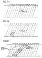
- Block shuffling circuit 101 divides the digital video signal into blocks each having a certain size to rearrange the video signal data on the basis of such block.
- the entire rectangular represents one whole screen.
- the entire screen is divided into six regions of A, B, C, D, E and F.
- Each region is further divided into small rectangular units (small blocks), where small blocks in each region are indicated by numbers such as 1, 2, 3, ... .
- region A is formed of a plurality of small blocks of A1, A2, A3, ...
- region B is formed of the same number of small blocks of B1, B2, B3, ... .
- the same can be said for the remaining regions C, D, E and F.
- Block shuffling circuit 101 divides the supplied digital video signal constituting an entire screen into the above-described rectangular units (small blocks). Then, the digital video signal is rearranged on a small block basis in such arrangement that small blocks are sequentially derived one by one from respective regions of A-F in ascending order, such as A1, B1, C1, D1, E1, F1, A2, B2, C2, D2, E2, F2, A3, ....
- Each group of small blocks of a corresponding number read out from the respective six regions A-F for example a group of (A1, B1, C1, D1, E1, F1), a group of (A2, B2, C2, D2, E2, F2) ..., is defined as one "large block".
- bit rate reduction coding circuit 102 where bit rate reduction coding of data on the basis of the above-described large block is carried out to realize an amount of information suitable for recording onto a tape. More specifically, a video signal of each small block entered into bit rate reduction coding circuit 102 is subjected to the well-known orthogonal transform coding, and then subjected to a variable length coding process according to the information amount of each small block so that the coded amount of a large block becomes constant. As a result, reduction of the data amount, i.e. bit rate reduction coding is realized.
- the data of the plurality of small blocks constituting each large block are gathered together to be provided as a block data of a fixed length to be supplied to an error correction coding circuit 103.
- Error correction coding circuit 103 adds an error correction code (parity) to the block data of a fixed length subjected to bit rate reduction coding, which is supplied to a synchronizing signal-ID signal applying circuit 104.
- Synchronizing signal-ID signal applying circuit 104 adds a synchronizing signal and an ID signal to the supplied video signal to provide the same to a modulation circuit 105.
- Modulation circuit 105 modulates the supplied signal while suppressing the direct current (DC) component thereof to record the same on the above-described fixed length block basis on a magnetic tape 107 as a recording medium via a magnetic head 106.
- Fig. 3 shows the recording manner on such a tape.
- Each track is constituted by a plurality of block data of a fixed length M1, M2, M3, M4, ....
- recorded data M1, M2, M3, ... on tape 107 such as that shown in Fig. 3 are reproduced via a magnetic head 108 to be demodulated by a demodulation circuit 109.
- the demodulated video signal is supplied to a synchronizing signal-ID signal detection circuit 110 where detection of a synchronizing signal and an ID signal is carried out. Then, the video signal is applied to an error correction decoding circuit 111.
- Error correction decoding circuit 111 carries out error correction to the applied video signal, and variable length decoding and inverse orthogonal transform process for data of each of small blocks forming the fixed length block to restore the original data of each small block.
- the restored data is supplied to a decoding-concealment circuit 112 where decoding and concealment of a video signal are carried out for the portion of data where error correction could not be carried out in error correction decoding circuit 111.
- the data subjected to an error correction and decoding process is supplied to a block de-shuffling circuit 113 where a inverse rearrangement of the rearrangement by block shuffling circuit 101 of the recording system is carried out.
- a block de-shuffling circuit 113 where a inverse rearrangement of the rearrangement by block shuffling circuit 101 of the recording system is carried out.
- the data signal of block de-shuffling circuit 113 is output appropriately to be provided to a monitor device and the like not shown.
- a plurality of small blocks that are located distant from each other on a screen (for example, A1, B1, C1, D1, E1, F1) are gathered together to form a large block, and control of the code amount is carried out on the basis of this large block to form a data block of a fixed length (for example M1) to be recorded on a tape. Therefore, corresponding small blocks (for example A1 and A2, B1 and B2) of two data of fixed length recorded adjacent to each other on a tape (for example M1 and M2) are the small blocks adjacent to each other on the screen.
- the deviation of the amount of information of video data is considered to be necessarily small between two adjacent small blocks on the screen. Therefore, deviation in each information amount of fixed length data (M1, M2, ...) recorded adjacent to each other on a tape is less likely to occur, so that the video signal can be transmitted with the desired quality of picture, that is, efficiency of bit rate reduction coding can be improved.
- the manner of block division of a screen in the above-described conventional VTR had a problem set forth in the following. From the standpoint of further improving the efficiency of bit rate reduction coding, it is preferable to divide the entire screen into as many regions as possible to increase the number of small blocks included in each large block (fixed length block) to suppress deviation in the information amount of each fixed length block data. However, from the standpoint of ensuring good visual quality of the reproduced picture at the time of high speed reproduction, it is preferable to reduce the number of small blocks included in each large block (fixed length block) to ensure continuity of data on a screen for preventing mosaic deformation on the screen.
- adjacent small blocks on a screen are the two small blocks corresponding to each other in the two adjacent fixed length blocks (for example M1 and M2) on the tape
- 1/6 (for example, 5 small blocks) of the small blocks for example, 30 small blocks
- the mosaic deformation is usually caused by generation of a large number of boundaries among blocks belonging to different fields. In order to present such mosaic deformation, therefore, it is required that small blocks belonging to the same field is reproduced on the screen as many as possible.
- the design parameter of a digital VTR particularly the number of small blocks included in each fixed length block can be determined only by a compromise between the efficiency of bit rate reduction coding and the visual quality of a high speed reproduced picture, resulting in a problem that the design of a digital VTR significantly lacks degree of flexibility.
- An object of the present invention is to provide a digital recording and/or reproduction apparatus of a video signal having the efficiency of bit rate reduction coding of a video signal improved.
- Another object of the present invention is to provide a digital recording and/or reproduction apparatus of a video signal having the picture quality of a reproduced picture at the time of high speed reproduction improved.
- a further object of the present invention is to provide a digital recording and/or reproduction apparatus of a video signal promoting individually optimization of bit rate reduction coding and optimization of picture quality of high speed reproduction.
- an apparatus for recording digitally a digital video signal comprises a circuit for forming a plurality of small blocks each having a plurality of pixels in the horizontal direction and the vertical direction of the digital video signal, a circuit for forming a plurality of large blocks each having a plurality of small blocks located distant from each other on a screen, a circuit for coding the digital video signal for each of the small blocks constituting the large block, a circuit for controlling the code amount for each large block so that the total code amount of the plurality of small blocks constituting the large block is constant to form a fixed length block, a circuit for dividing the fixed length block into a plurality of recording blocks so that respective main components (important for decoding of video data) of the plurality of small blocks constituting the fixed length block are included separately in the plurality of recording blocks, a circuit for applying coding for error correction to be made at the time of reproduction to the plurality of recording blocks to form a plurality of error correction blocks, a circuit for rearranging the plurality of recording blocks
- an apparatus for reproducing digitally a digital video signal recorded as described above comprises a circuit for detecting a plurality of recording blocks recorded on a recording medium, a circuit for rearranging the detected recording blocks on the basis of the recording block to be included in the plurality of error correction blocks in the original order prior to recording, a circuit for restoring the recording blocks at the time of recording by applying an error correction process to the rearranged recording blocks to correct an error generated at the time of reproduction, a circuit for reconstructing a fixed length block from the plurality of recording blocks constituting a large block, a circuit for decoding a digital video signal for each of the plurality of small blocks constituting the reconstructed fixed length block, a circuit for concealing the contents of each small block to reduce the effect of an error to a reproduced picture when error correction could not be carried out by the error correction circuit, and a circuit for rearranging the plurality of small blocks constituting the fixed length block to restore pixels corresponding to the digital video signal at the time of recording.
- an apparatus for digital-recording a supplied digital video signal and for digital-reproducing a recorded digital video signal includes a circuit for forming a plurality of small blocks, each including a plurality of pixels in the horizontal direction and the vertical direction of the digital video signal, a circuit for forming a plurality of large blocks, each including a plurality of the small blocks located distant from each other on a screen, a circuit for coding a digital video signal for each of the small blocks constituting the large block, a circuit for controlling the code amount for each large block so that the total code amount of the plurality of small blocks constituting the large block is constant to form a fixed length block, a circuit for dividing the fixed length block into a plurality of recording blocks so that respective main components of the plurality of small blocks constituting the fixed length block are included separately in the plurality of recording blocks, a circuit for applying coding for error correction to be made at the time of reproduction to the plurality of recording blocks to form a plurality of error correction blocks,
- a main advantage of the present invention is to reduce the possibility of deviation in the information amount of each large block to improve the efficiency of bit rate reduction coding by controlling the code amount of the large block formed by a plurality of small blocks located distant from each other on a screen to form a fixed length block, dividing the fixed length block so that the main components of respective small blocks are included separately on recording blocks, and rearranging error correction blocks so that recording blocks including the main components of small blocks adjacent on the screen are also adjacent on the recording medium.
- Another advantage of the present invention is to prevent mosaic deformation of a high speed reproduced picture to obtain a high speed reproduced picture of high visual quality, because the number of small blocks detected continuously on a track at the time of high speed reproduction are directly the number of small blocks successive on a screen.
- a further advantage of the present invention is to allow arbitrary setting of design parameters to achieve a desired efficiency of bit rate reduction coding regardless of the picture quality of a high speed reproduced picture.
- Fig. 1 is a block diagram schematically showing a structure of a conventional digital VTR.
- Fig. 2 schematically shows a manner of block division of a screen according to a bit rate reduction coding method.
- Fig. 3 schematically shows a data arrangement in a track formed on a tape by a conventional digital VTR.
- Fig. 4 is a block diagram schematically showing a structure of a digital VTR according to an embodiment of the present invention.
- Fig. 5 is a diagram schematically showing a manner of block division of a screen according to an embodiment of the present invention.
- Fig. 6 schematically shows a structure of a fixed length block according to an embodiment of the present invention.
- Figs. 7 and 8 schematically show division methods of a fixed length block according to an embodiment of the present invention.
- Figs. 9A-9C schematically show data arrangement when four error correction blocks are formed according to an embodiment of the present invention.
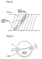
- Fig. 10 schematically shows the relationship between record tracks formed on a tape by a digital VTR according to an embodiment of the present invention and a trace of a head at the time of high speed reproduction.
- Fig. 11 schematically shows an example of an arrangement of heads used in a multichannel-multisegment recording method.
- Figs. 12A-12C schematically shows tracks formed by a digital VTR according to a multichannel-multisegment recording method.
- Fig. 4 is a block diagram schematically showing a structure of a digital VTR according to an embodiment of the present invention.
- a digital video signal provided from a video signal source not shown is supplied to a small blocking circuit 1 included in a digital VTR.
- small blocking circuit 1 combines a plurality of pixels in the horizontal direction and the vertical direction of a digital video signal to form a plurality of rectangular units (small blocks of data) A1, A2, ..., B1, B2, ..., C1, C2, ..., D1, D2, ..., as shown in Fig. 5.
- the digital video signal rearranged in such a manner is supplied to a large blocking circuit 2.
- Large blocking circuit 2 rearranges the digital video signal on the basis of small block by deriving in ascending order small blocks sequentially one by one from regions A, B, C and D obtained by dividing the entire screen into four as shown in Fig. 5, resulting in a plurality of large blocks (A1, B1, C1, D1), (A2, B2, C2, D2), ... .
- the digital video signal rearranged in such a manner is supplied to an orthogonal transform circuit 3.
- Orthogonal transform circuit 3 applies an orthogonal transform process to the entered digital video signal of each small block using a well known method such as discrete cosine conversion, and supplies the same to a variable length coding circuit 4.
- Variable length coding circuit 4 applies a variable length coding process for each small block according to the amount of information of each entered small block. Although the code amount of information of each small block is variable in the variable length coding process for each small block, variable length coding circuit 4 carries out control so that the total of the code length of the plurality of small blocks forming each large block is a fixed value, whereby a data block of a fixed length corresponding to each large block is obtained.
- variable length coding circuit 4 controls the code amount so that the total of the code amount of information in each large block is equal.
- a digital video signal subjected to variable length coding process as described above is supplied to a recording blocking circuit 5, whereby data division is carried out to form recording blocks which will be described afterwards.
- the code of each block forming a fixed length block as shown in Fig. 6 includes additional information representing the code length after coding, followed by real information having video information from a low frequency component to a high frequency component after orthogonal transformation disposed sequentially from the low frequency component.
- the above-mentioned additional information and the real information of a low frequency component are called the main components of information among the information included in a fixed length block.
- Recording blocking circuit 5 carries out data division of each fixed length block so that the above-mentioned main components of the plurality of small blocks constituting the fixed length block are included in separate recording blocks.
- divisional methods there are two methods, that is, a first method schematically shown in Fig. 7 and a second method schematically shown in Fig. 8.
- Fig. 7 shows the case where one fixed length block is divided into recording blocks of 1-5. From the information of small blocks A-D constituting one fixed length block, the main component information of respective small blocks are separately disposed into recording blocks 1-4, and components that are not so important and not included in the main components, such as high frequency information, are gathered from the respective four small blocks to be arranged in one additional recording block 5. Division of a fixed length block into recording blocks of 1-5 is carried out in such a manner.
- Fig. 8 shows the case where one fixed length block is divided into recording blocks of 1-4. More specifically, the average code length of small blocks A-D constituting one fixed length block is determined as the code length for each recording block, and information of respective small blocks A-D are disposed separately into recording blocks 1-4. The information, which could not be stored in the corresponding recording block, of a small block having a code length longer than the average value is stored into an empty region of another recording block where data of a small block having a code length shorter than the average value is stored. Division of a fixed length block into recording blocks 1-4 is carried out in such a manner.
- the first method of Fig. 7 is characterized in that the main components of respective small blocks can readily be divided into separate recording blocks, and that only the information required for high speed reproduction can be reliably detected because the main components of a video signal are recorded in one group.
- the second method of Fig. 8 is characterized in that the main components of respective small blocks can readily be divided into separate recording blocks and that every recording block necessarily includes the main components of the corresponding small block so that one small block can be surely reproduced if one recording block can be reproduced at the time of high speed reproduction.
- the video signal provided from recording blocking circuit 5 is supplied to error correction coding circuit 6 where an error correction code (parity) is added for correcting an error to be generated in a reproduction system. More specifically, the error correction coding process is carried out using the well known Read-Solomon product codes of outer codes and inner codes, resulting in a plurality of error correction blocks. In each error correction block, the above-described recording blocks are stored in one-to-one correspondence with inner codes.
- Figs. 9A-9C schematically show the data arrangement in case of forming 4 error correction blocks according to the present invention. More specifically, Fig. 9A corresponds to the divided screen of Fig. 5 where the recording blocks corresponding to small blocks of A1, A2, A3, A4, ..., B1, B2, B3, B4, ..., C1, C2, C3, C4, ..., D1, D2, D3, D4, ... on a screen are sequentially stored in error correction blocks of the corresponding numbers, as shown in Fig. 9B. For example, recording blocks of A1, B1, C1, D1, ... are stored in the first error correction block as the outer code with the outer parity added, and A2, B2, C2, D2, ... are stored in the second error correction block as the outer code with the outer parity added. The remaining recording blocks are sequentially stored in the corresponding error correction blocks in a similar manner.
- Rearranging circuit 7 rearranges the recording blocks arranged as shown in Fig. 9B as that shown in Fig. 9C where small blocks adjacent on a screen (for example A1, A2, A3, A4, ...) are also adjacent on a track when recorded on a tape.
- Recording blocks rearranged in such a manner are modulated by a modulation circuit not shown to be recorded on a magnetic tape 9 via a magnetic head 8.
- inner codes corresponding to respective adjacent small blocks on a screen are included in a distributed manner in separate error correction blocks (for example, in the first and second error correction blocks of Fig. 9B).
- small blocks adjacent on a screen (A1 and A2) have data rearranged so as to be adjacent even on the recording track as shown in Fig. 9C. Therefore, at the time of reproduction, inner codes are sequentially derived one by one from the four error correction blocks.
- the data arrangement of the present invention as described-above provides an effect that the length of a burst error that can be corrected with outer codes is quadrupled. There is also an advantage of improving the visual quality of the picture at the time of high speed reproduction.
- the small blocks A1, A2, A3, A4, ... of recorded data on tape 9 shown in Fig. 9C are reproduced via a magnetic head 10, and demodulated by a demodulation circuit not shown.
- the demodulated video signal is supplied to a inverse rearranging circuit 11 where the plurality of the error correction blocks have the small blocks rearranged to the original arrangement shown in Fig. 9B.
- Error correction decoding circuit 12 carries out error correction to the supplied video signal for correcting an error generated at the time of reproduction, whereby the original recording blocks are restored and supplied to a recording block decomposition circuit 13. Error correction decoding circuit 12 applies an error flag to a recording block (small block) that could not be corrected, and provides the same to recording block decomposition circuit 13.
- Recording block decomposition circuit 13 decomposes the recording block formed as shown in Fig. 9B to rearrange data so that coded data is restored for each small block constituting a fixed length block shown in Fig. 6. The resulting data is supplied to a first concealment circuit 14.
- first concealment circuit 14 replaces such not-important components with "0", for example, and cancels the error flag applied by error correction decoding circuit 12. If there is an error in the portion of a recording block, where the main components of the corresponding small block are included, first concealment circuit 14 generates an error flag which is supplied to a second concealment circuit 17 at the succeeding stage.
- variable length decoding circuit 15 applies a variable length decoding process of coded data for each small block to provide the same to a inverse orthogonal transform circuit 16.
- Inverse orthogonal transform circuit 16 applies an orthogonal transform process opposite to that at the time of recording to the data of each small block to obtain pixels for each small block.
- the video signal of a small block having the not-important components replaced by "0" due to an error by first concealment circuit 14 has its high frequency components slightly lost, it is possible to obtain a reproduced picture having a picture quality of a certain level. If there is an error in the portion of the recording block, where the main components of the corresponding small block are included, and an error flag has been supplied to second concealment circuit 17 by first concealment circuit 14, the pixels of that small block are replaced by pixels of a small block at the same position on a preceding screen by second concealment circuit 17.
- the pixels obtained for each small block are supplied to a large block decomposition circuit 18.
- Large block decomposition circuit 18 rearranges the small blocks as shown in Fig. 9A for reproduction on their respective positions on the screen.
- Small block decomposition circuit 19 decomposes the pixels of each small block to reproduce the arrangement of the digital video signal in the same manner as that of the digital video signal supplied to small blocking circuit 1 at the time of recording.
- the reproduced digital video signal is supplied to a monitor device not shown. Thus, display of a reproduced picture is possible.
- Fig. 10 schematically shows the relationship between record tracks formed on a tape by a digital VTR according to the above-described embodiment, and a trace of a head at the time of high speed reproduction.
- a head for reproduction traverses the plurality of record tracks formed on the tape for scanning.
- a video signal can be detected from every other track using one head, as shown by the shaded line in Fig. 10.
- data of small blocks adjacent on a screen for example, A1, A2, A3, A4, ...) are recorded successively on the basis of an inner code, as described in association with Fig. 9C, so that a signal can be detected with a certain continuity as such shown in Fig. 10 even at the time of high speed reproduction.
- inner codes adjacent on a record track have the main components of the small blocks located adjacent on a screen stored, as described in association with Figs. 9A-9C, so that the number of inner codes that could be detected successively on the record track (the shaded region of Fig. 10) at the time of high speed reproduction is directly the number of small blocks continuous on the screen.
- mosaic deformation on a screen at the time of high speed reproduction can be prevented to obtain a picture of high visual picture quality at the time of high speed reproduction.
- the so-called multichannel-multisegment recording method is employed in a conventional digital VTR wherein data of one screen is divided into a plurality of tracks to be recorded using a plurality of heads, considering the great amount of information of digital video signals to be recorded.
- An embodiment will be described hereinafter where the present invention is applied to a digital VTR of a multichannel-multisegment recording method.
- Fig. 11 schematically shows an example of an arrangement of heads used in a multichannel-multisegment recording method.
- the four heads shown in Fig. 11 are used to divide digital video signal data of one screen into four tracks to be recorded.
- heads a1 and a2 are + azimuth heads
- heads b1 and b2 are - azimuth heads.
- video data of one screen is recorded on a tape using the two pairs, i.e. a total of four heads, for every rotation of the rotary drum of Fig. 11.
- Fig. 12A shows the case where data of one screen is recorded in four tracks using the four heads.
- the area indicated by a thick solid line shows the region where data of one screen is recorded
- the two regions defined by dividing such region into two by a thin solid line are regions respectively formed by the head pairs of a1 and b1, and a2 and b2.
- Each region defined by a dotted line corresponds to a track formed by each head.
- error correction coding circuit 6 forms a plurality of error correction blocks (m blocks) to store recording blocks for each error correction blocks.
- m blocks error correction blocks
- the number of the inner codes is X and the number of the inner codes corresponding to the recording blocks including the main components of small blocks is Y for each correction block in case where the number of tracks is 4, for example, as in the case of embodiment.
- the number X should be a multiple of 4 and, particularly in view of the necessity that the real data as well as the parity data should be equally distributed, the number Y should be a multiple of 4 as well.
- respective error correction blocks have data arranged so that inner codes including the main components of small blocks adjacent on a screen are distributed onto separate error correction blocks.
- rearranging circuit 7 functions to arrange data so that inner codes including the main components of small blocks adjacent on a screen are adjacent even on tracks
- the two tracks (the regions defined by a thin solid line and a thick solid line) formed by the head pairs of a1 and b1, or a2 and b2 are taken as one track, in which data is rearranged as in the arrangement shown in Fig. 12B in the present embodiment.
- rearranging circuit 7 carries out rearrangement of data so that inner codes including small blocks adjacent on a screen are alternately recorded on the pair of tracks in a sequence, such as block A1 to track a1, block A2 to track b1, block A3 to track a1, block A4 to track b1, block A5 to track b1, block A6 to track a1, block A7 to track b1, block A8 to track a1.
- the invention may be implemented so that the order of arrangement is exchanged between blocks A1-A4 and blocks A5-A8 when error correction blocks are to be formed by error correction coding circuit 6, and then allocated to the pair of tracks as they are in rearranging data on the track by rearranging circuit 7.
- Fig. 12C schematically shows the relationship between record tracks on a tape formed as shown in Fig. 12B and the trace of a head pair (for example, head a1 and b1) at the time of high speed reproduction.
- a head pair for example, head a1 and b1
- the regions of tracks a1 and a2 and a1 (shaded area) scanned by head a1 to have recorded data detected, and the regions of different azimuth tracks b1 and b2 and b1 (shaded area) scanned by head b1 to have recorded data detected are located in substantially corresponding positions.
- the present invention is applicable to the recording/reproduction method of tapes of various formats where a similar effect can be obtained by rearranging data according to that recording/reproduction method.
- recording blocks and inner codes are in one-to-one correspondence. If the code length of each recording block is too long, one recording block can be divided to correspond to a plurality of inner codes taking into account the ability of error correction by inner codes. Conversely, if the code length of each recording block is too short and is disadvantageous from the standpoint of redundancy, a plurality of recording blocks including the main components of a plurality of small blocks adjacent on a screen can be combined to correspond to one inner code.
- the present invention has the screen divided into four as an example of obtaining a desired efficiency of bit rate reduction coding and a reproduced picture of high quality at the time of high speed reproduction, the present invention is not limited to this division of 4, and is applicable to a case where the screen is divided into another manner.
- a screen can be divided into an arbitrary number for achieving a desired efficiency of bit rate reduction coding independent of the picture quality of a high speed reproduced picture.
Landscapes
- Engineering & Computer Science (AREA)
- Multimedia (AREA)
- Signal Processing (AREA)
- Television Signal Processing For Recording (AREA)
- Signal Processing For Digital Recording And Reproducing (AREA)
Applications Claiming Priority (4)
| Application Number | Priority Date | Filing Date | Title |
|---|---|---|---|
| JP4006301A JP2664112B2 (ja) | 1992-01-17 | 1992-01-17 | 映像信号のディジタル記録及び再生装置 |
| JP6301/92 | 1992-01-17 | ||
| JP630192 | 1992-01-17 | ||
| EP93300250A EP0552049B1 (fr) | 1992-01-17 | 1993-01-15 | Appareil d'enregistrement et/ou de reproduction digitale d'un signal vidéo |
Related Parent Applications (2)
| Application Number | Title | Priority Date | Filing Date |
|---|---|---|---|
| EP93300250A Division EP0552049B1 (fr) | 1992-01-17 | 1993-01-15 | Appareil d'enregistrement et/ou de reproduction digitale d'un signal vidéo |
| EP93300250.3 Division | 1993-01-15 |
Publications (3)
| Publication Number | Publication Date |
|---|---|
| EP0801498A2 true EP0801498A2 (fr) | 1997-10-15 |
| EP0801498A3 EP0801498A3 (fr) | 1997-11-05 |
| EP0801498B1 EP0801498B1 (fr) | 2000-12-06 |
Family
ID=11634556
Family Applications (2)
| Application Number | Title | Priority Date | Filing Date |
|---|---|---|---|
| EP97110447A Expired - Lifetime EP0801498B1 (fr) | 1992-01-17 | 1993-01-15 | Appareil d'enregistrement et/ou reproduction digital d'un signal vidéo |
| EP93300250A Expired - Lifetime EP0552049B1 (fr) | 1992-01-17 | 1993-01-15 | Appareil d'enregistrement et/ou de reproduction digitale d'un signal vidéo |
Family Applications After (1)
| Application Number | Title | Priority Date | Filing Date |
|---|---|---|---|
| EP93300250A Expired - Lifetime EP0552049B1 (fr) | 1992-01-17 | 1993-01-15 | Appareil d'enregistrement et/ou de reproduction digitale d'un signal vidéo |
Country Status (9)
| Country | Link |
|---|---|
| US (1) | US5309292A (fr) |
| EP (2) | EP0801498B1 (fr) |
| JP (1) | JP2664112B2 (fr) |
| KR (1) | KR960006845B1 (fr) |
| CN (4) | CN1040933C (fr) |
| DE (2) | DE69329739T2 (fr) |
| ES (2) | ES2134826T3 (fr) |
| HK (1) | HK1002216A1 (fr) |
| MY (1) | MY109117A (fr) |
Families Citing this family (30)
| Publication number | Priority date | Publication date | Assignee | Title |
|---|---|---|---|---|
| EP0497545B1 (fr) * | 1991-01-29 | 1997-01-08 | Canon Kabushiki Kaisha | Dispositif de codage de signal d'image |
| US5473479A (en) * | 1992-01-17 | 1995-12-05 | Sharp Kabushiki Kaisha | Digital recording and/or reproduction apparatus of video signal rearranging components within a fixed length block |
| EP1137280B1 (fr) * | 1992-01-29 | 2003-04-02 | Mitsubishi Denki Kabushiki Kaisha | Dispositif et procédé d'enregistrement/reproduction de l'information vidéo |
| US6870884B1 (en) * | 1992-01-29 | 2005-03-22 | Mitsubishi Denki Kabushiki Kaisha | High-efficiency encoder and video information recording/reproducing apparatus |
| US5589994A (en) * | 1992-08-21 | 1996-12-31 | Mitsubishi Denki Kabushiki Kaisha | Image recording method and apparatus with reduced error propagation |
| JPH06153151A (ja) * | 1992-10-31 | 1994-05-31 | Sony Corp | ディジタルビデオ信号記録装置 |
| JP2855067B2 (ja) * | 1992-11-28 | 1999-02-10 | 三星電子株式会社 | デジタルvcrの画像記録方法 |
| JP2651100B2 (ja) * | 1993-02-17 | 1997-09-10 | 松下電器産業株式会社 | ディジタル磁気記録再生装置 |
| DE4308235A1 (de) * | 1993-03-10 | 1994-09-15 | Thomson Brandt Gmbh | Verfahren zur Speicherung oder Wiedergabe von Datenpaketen |
| TW323029U (en) * | 1993-06-30 | 1997-12-11 | Victor Company Of Japan Co Ltd | Processing system for digital video signal |
| JPH07105638A (ja) * | 1993-10-05 | 1995-04-21 | Matsushita Electric Ind Co Ltd | 画像データの記録再生装置 |
| AU701481B2 (en) * | 1994-04-08 | 1999-01-28 | Koninklijke Philips Electronics N.V. | Recording and reproducing an MPEG information signal on/from a record carrier |
| US5579183A (en) * | 1994-04-08 | 1996-11-26 | U.S. Philips Corporation | Recording and reproducing an MPEG information signal on/from a record carrier |
| EP0684734B1 (fr) * | 1994-05-25 | 2000-09-13 | Canon Kabushiki Kaisha | Dispositif et procédé de détection de signal pilote d'un signal numérique ainsi qu'un appareil de reproduction |
| JP2912831B2 (ja) * | 1994-10-05 | 1999-06-28 | オリンパス光学工業株式会社 | 情報記録媒体及び情報再生装置 |
| JP3115199B2 (ja) * | 1994-12-16 | 2000-12-04 | 松下電器産業株式会社 | 画像圧縮符号化装置 |
| JP3351645B2 (ja) | 1995-01-31 | 2002-12-03 | 松下電器産業株式会社 | 動画像信号の符号化方法 |
| KR0151021B1 (ko) * | 1995-02-16 | 1998-10-15 | 김광호 | 디지탈 비디오 테이프 레코더의 비트스트림 배치/복원방법 및 그에 적합한 데이타압축장치 및 복원장치 |
| US5852706A (en) * | 1995-06-08 | 1998-12-22 | Sony Corporation | Apparatus for recording and reproducing intra-frame and inter-frame encoded video data arranged into recording frames |
| CA2180189C (fr) * | 1995-08-03 | 2001-07-03 | Satoru Adachi | Dispositif de transmission de donnees codees de longueur variable |
| US5926610A (en) * | 1995-11-15 | 1999-07-20 | Sony Corporation | Video data processing method, video data processing apparatus and video data recording and reproducing apparatus |
| JP2001043616A (ja) | 1999-07-30 | 2001-02-16 | Sharp Corp | 記録方法、記録媒体及び記録装置 |
| JP3887593B2 (ja) * | 2002-10-15 | 2007-02-28 | シャープ株式会社 | オフセット補正装置およびオフセット補正方法 |
| US7116840B2 (en) * | 2002-10-31 | 2006-10-03 | Microsoft Corporation | Decoding and error correction in 2-D arrays |
| JP4598374B2 (ja) * | 2003-06-12 | 2010-12-15 | パナソニック株式会社 | 画像処理装置 |
| JP5443516B2 (ja) * | 2009-06-25 | 2014-03-19 | ジーブイビービー ホールディングス エス.エイ.アール.エル. | マクロブロック・シャッフリング装置、シャッフリング方法、及びシャッフリング・プログラム |
| US10003803B1 (en) | 2012-04-18 | 2018-06-19 | Matrox Graphics Inc. | Motion-based adaptive quantization |
| US9300984B1 (en) * | 2012-04-18 | 2016-03-29 | Matrox Graphics Inc. | Independent processing of data streams in codec |
| US10003802B1 (en) | 2012-04-18 | 2018-06-19 | Matrox Graphics Inc. | Motion-based adaptive quantization |
| JP2015177221A (ja) * | 2014-03-13 | 2015-10-05 | オリンパス株式会社 | 撮像装置、撮像方法、データ記録装置、及びプログラム |
Citations (4)
| Publication number | Priority date | Publication date | Assignee | Title |
|---|---|---|---|---|
| WO1991002430A1 (fr) * | 1989-08-03 | 1991-02-21 | Deutsche Thomson-Brandt Gmbh | Systeme de traitement numerique des signaux |
| EP0471118A1 (fr) * | 1990-08-13 | 1992-02-19 | Matsushita Electric Industrial Co., Ltd. | Appareil numérique d'enregistrement et de reproduction d'un signal vidéo |
| EP0512623A2 (fr) * | 1991-05-10 | 1992-11-11 | Koninklijke Philips Electronics N.V. | Système de télévision pour la transmission de signaux d'images en format numérique |
| EP0559467A2 (fr) * | 1992-03-05 | 1993-09-08 | Matsushita Electric Industrial Co., Ltd. | Dispositif d'enregistrement et/ou de reproduction d'un signal vidéo numérique |
Family Cites Families (5)
| Publication number | Priority date | Publication date | Assignee | Title |
|---|---|---|---|---|
| JP2900385B2 (ja) * | 1988-12-16 | 1999-06-02 | ソニー株式会社 | フレーム化回路及び方法 |
| US5073821A (en) * | 1989-01-30 | 1991-12-17 | Matsushita Electric Industrial Co., Ltd. | Orthogonal transform coding apparatus for reducing the amount of coded signals to be processed and transmitted |
| JP2953704B2 (ja) * | 1989-02-20 | 1999-09-27 | 松下電器産業株式会社 | ディジタル映像信号記録及び再生方法 |
| JPH04177992A (ja) * | 1990-11-09 | 1992-06-25 | Victor Co Of Japan Ltd | 階層性を有する画像符号化装置 |
| JP3141896B2 (ja) * | 1991-08-09 | 2001-03-07 | ソニー株式会社 | ディジタルビデオ信号の記録装置 |
-
1992
- 1992-01-17 JP JP4006301A patent/JP2664112B2/ja not_active Expired - Lifetime
-
1993
- 1993-01-15 DE DE69329739T patent/DE69329739T2/de not_active Expired - Lifetime
- 1993-01-15 US US08/005,382 patent/US5309292A/en not_active Expired - Lifetime
- 1993-01-15 EP EP97110447A patent/EP0801498B1/fr not_active Expired - Lifetime
- 1993-01-15 DE DE69325933T patent/DE69325933T2/de not_active Expired - Lifetime
- 1993-01-15 ES ES93300250T patent/ES2134826T3/es not_active Expired - Lifetime
- 1993-01-15 ES ES97110447T patent/ES2153146T3/es not_active Expired - Lifetime
- 1993-01-15 MY MYPI93000066A patent/MY109117A/en unknown
- 1993-01-15 EP EP93300250A patent/EP0552049B1/fr not_active Expired - Lifetime
- 1993-01-16 CN CN93100402A patent/CN1040933C/zh not_active Expired - Lifetime
- 1993-01-16 CN CNB981039545A patent/CN1166196C/zh not_active Expired - Lifetime
- 1993-01-16 KR KR1019930000525A patent/KR960006845B1/ko not_active IP Right Cessation
-
1998
- 1998-01-03 CN CN98103953A patent/CN1126365C/zh not_active Expired - Lifetime
- 1998-01-03 CN CN98103955A patent/CN1126364C/zh not_active Expired - Lifetime
- 1998-02-18 HK HK98101238A patent/HK1002216A1/xx not_active IP Right Cessation
Patent Citations (4)
| Publication number | Priority date | Publication date | Assignee | Title |
|---|---|---|---|---|
| WO1991002430A1 (fr) * | 1989-08-03 | 1991-02-21 | Deutsche Thomson-Brandt Gmbh | Systeme de traitement numerique des signaux |
| EP0471118A1 (fr) * | 1990-08-13 | 1992-02-19 | Matsushita Electric Industrial Co., Ltd. | Appareil numérique d'enregistrement et de reproduction d'un signal vidéo |
| EP0512623A2 (fr) * | 1991-05-10 | 1992-11-11 | Koninklijke Philips Electronics N.V. | Système de télévision pour la transmission de signaux d'images en format numérique |
| EP0559467A2 (fr) * | 1992-03-05 | 1993-09-08 | Matsushita Electric Industrial Co., Ltd. | Dispositif d'enregistrement et/ou de reproduction d'un signal vidéo numérique |
Non-Patent Citations (2)
| Title |
|---|
| IEEE TRANSACTIONS ON CONSUMER ELECTRONICS, vol. 37, no. 3, 1 August 1991, pages 261-266, XP000263194 YAMAMITSU C ET AL: "A STUDY ON TRICK PLAYS FOR DIGITAL VCR" * |
| SIGNAL PROCESSING OF HDTV, 3, TURIN, SEPT. 4 - 6, 1991, no. WORKSHOP 4, 4 September 1991, YASUDA H;CHIARIGLIONE L, pages 33-41, XP000379936 KAUFF P ET AL: "A DCT CODING SCHEME FOR DIGITAL HDTV RECORDING" * |
Also Published As
| Publication number | Publication date |
|---|---|
| US5309292A (en) | 1994-05-03 |
| CN1203498A (zh) | 1998-12-30 |
| KR960006845B1 (ko) | 1996-05-23 |
| EP0801498A3 (fr) | 1997-11-05 |
| HK1002216A1 (en) | 1998-08-07 |
| ES2134826T3 (es) | 1999-10-16 |
| DE69329739D1 (de) | 2001-01-11 |
| KR930016943A (ko) | 1993-08-30 |
| JPH06290549A (ja) | 1994-10-18 |
| DE69325933T2 (de) | 2000-01-20 |
| MY109117A (en) | 1996-12-31 |
| CN1166196C (zh) | 2004-09-08 |
| JP2664112B2 (ja) | 1997-10-15 |
| CN1040933C (zh) | 1998-11-25 |
| ES2153146T3 (es) | 2001-02-16 |
| EP0801498B1 (fr) | 2000-12-06 |
| CN1126364C (zh) | 2003-10-29 |
| DE69329739T2 (de) | 2001-05-23 |
| CN1203496A (zh) | 1998-12-30 |
| EP0552049A2 (fr) | 1993-07-21 |
| CN1075387A (zh) | 1993-08-18 |
| DE69325933D1 (de) | 1999-09-16 |
| CN1203497A (zh) | 1998-12-30 |
| EP0552049B1 (fr) | 1999-08-11 |
| CN1126365C (zh) | 2003-10-29 |
| EP0552049A3 (fr) | 1994-03-30 |
Similar Documents
| Publication | Publication Date | Title |
|---|---|---|
| EP0801498B1 (fr) | Appareil d'enregistrement et/ou reproduction digital d'un signal vidéo | |
| US5473479A (en) | Digital recording and/or reproduction apparatus of video signal rearranging components within a fixed length block | |
| EP0367264B1 (fr) | Enregistreur à bande vidéo numérique permettant une reproduction d'images à haute vitesse | |
| EP0527611B1 (fr) | Dispositif d'enregistrement de signal vidéo numérique | |
| US5434677A (en) | Digital video signal reproducing apparatus with high-speed play mode | |
| EP0644691B1 (fr) | Appareils d'enregistrement et de reproduction de signaux vidéo comprimés | |
| US5101274A (en) | Digital signal recording apparatus time-division multiplexing video and audio signals | |
| USRE37312E1 (en) | Digital recording and/or reproducing apparatus which rearranges error correction blocks representing video signal and corresponding to data blocks of image represented by video signal | |
| US6081649A (en) | Digital VTR for processing intra-picture data according to replay modes | |
| US5583651A (en) | Method of and system for transmitting and receiving digitally encoded video images | |
| US5499144A (en) | Magnetic recording/playback apparatus which shifts the head scan by a 1/2 tr | |
| US5953486A (en) | Recording and reproducing apparatus | |
| KR100718833B1 (ko) | 비디오 데이타 처리 방법, 비디오 데이타 처리 장치 및비디오 데이타 기록 및 재생 장치 | |
| US7174090B2 (en) | Digital VTR | |
| JP3207739B2 (ja) | 画像再生装置 | |
| US6192182B1 (en) | Digital information signal recording apparatus and method thereof | |
| US5519547A (en) | Magnetic recording and reproducing apparatus recording and reproducing plural types of data signals at different data rates | |
| JP2869291B2 (ja) | 映像信号のディジタル記録及び再生装置 | |
| JP2869292B2 (ja) | 映像信号のディジタル記録及び再生装置 | |
| JP2869290B2 (ja) | 映像信号のディジタル記録及び再生装置 | |
| KR100213421B1 (ko) | 착오정정부호화 수단을 가진 기록장치 | |
| JP2633556B2 (ja) | 回転ヘッド式ビデオテープレコーダにおける音声データの記録方法 | |
| JPH01165281A (ja) | 伝送方法及び伝送装置 | |
| JPH0795512A (ja) | 記録再生装置 | |
| GB2324673A (en) | Digital VTR with header identification means |
Legal Events
| Date | Code | Title | Description |
|---|---|---|---|
| PUAI | Public reference made under article 153(3) epc to a published international application that has entered the european phase |
Free format text: ORIGINAL CODE: 0009012 |
|
| PUAL | Search report despatched |
Free format text: ORIGINAL CODE: 0009013 |
|
| AC | Divisional application: reference to earlier application |
Ref document number: 552049 Country of ref document: EP |
|
| AK | Designated contracting states |
Kind code of ref document: A2 Designated state(s): DE ES FR GB |
|
| AK | Designated contracting states |
Kind code of ref document: A3 Designated state(s): DE ES FR GB |
|
| RIN1 | Information on inventor provided before grant (corrected) |
Inventor name: TAKAKURA, EIICHI, MIKI-HOUSE 102 |
|
| 17P | Request for examination filed |
Effective date: 19980408 |
|
| GRAG | Despatch of communication of intention to grant |
Free format text: ORIGINAL CODE: EPIDOS AGRA |
|
| 17Q | First examination report despatched |
Effective date: 20000418 |
|
| GRAG | Despatch of communication of intention to grant |
Free format text: ORIGINAL CODE: EPIDOS AGRA |
|
| GRAH | Despatch of communication of intention to grant a patent |
Free format text: ORIGINAL CODE: EPIDOS IGRA |
|
| GRAH | Despatch of communication of intention to grant a patent |
Free format text: ORIGINAL CODE: EPIDOS IGRA |
|
| GRAA | (expected) grant |
Free format text: ORIGINAL CODE: 0009210 |
|
| AC | Divisional application: reference to earlier application |
Ref document number: 552049 Country of ref document: EP |
|
| AK | Designated contracting states |
Kind code of ref document: B1 Designated state(s): DE ES FR GB |
|
| REF | Corresponds to: |
Ref document number: 69329739 Country of ref document: DE Date of ref document: 20010111 |
|
| ET | Fr: translation filed | ||
| REG | Reference to a national code |
Ref country code: ES Ref legal event code: FG2A Ref document number: 2153146 Country of ref document: ES Kind code of ref document: T3 |
|
| PLBE | No opposition filed within time limit |
Free format text: ORIGINAL CODE: 0009261 |
|
| STAA | Information on the status of an ep patent application or granted ep patent |
Free format text: STATUS: NO OPPOSITION FILED WITHIN TIME LIMIT |
|
| 26N | No opposition filed | ||
| REG | Reference to a national code |
Ref country code: GB Ref legal event code: IF02 |
|
| PGFP | Annual fee paid to national office [announced via postgrant information from national office to epo] |
Ref country code: FR Payment date: 20120202 Year of fee payment: 20 |
|
| PGFP | Annual fee paid to national office [announced via postgrant information from national office to epo] |
Ref country code: DE Payment date: 20120111 Year of fee payment: 20 |
|
| PGFP | Annual fee paid to national office [announced via postgrant information from national office to epo] |
Ref country code: GB Payment date: 20120111 Year of fee payment: 20 |
|
| REG | Reference to a national code |
Ref country code: DE Ref legal event code: R071 Ref document number: 69329739 Country of ref document: DE |
|
| REG | Reference to a national code |
Ref country code: GB Ref legal event code: PE20 Expiry date: 20130114 |
|
| PG25 | Lapsed in a contracting state [announced via postgrant information from national office to epo] |
Ref country code: GB Free format text: LAPSE BECAUSE OF EXPIRATION OF PROTECTION Effective date: 20130114 Ref country code: DE Free format text: LAPSE BECAUSE OF EXPIRATION OF PROTECTION Effective date: 20130116 |
|
| PGFP | Annual fee paid to national office [announced via postgrant information from national office to epo] |
Ref country code: ES Payment date: 20120127 Year of fee payment: 20 |
|
| REG | Reference to a national code |
Ref country code: ES Ref legal event code: FD2A Effective date: 20130718 |
|
| PG25 | Lapsed in a contracting state [announced via postgrant information from national office to epo] |
Ref country code: ES Free format text: LAPSE BECAUSE OF EXPIRATION OF PROTECTION Effective date: 20130116 |