EP0801276A2 - Bâtiment avec zones de parois ou d'appui utilisant l'énergie solaire - Google Patents
Bâtiment avec zones de parois ou d'appui utilisant l'énergie solaire Download PDFInfo
- Publication number
- EP0801276A2 EP0801276A2 EP97101744A EP97101744A EP0801276A2 EP 0801276 A2 EP0801276 A2 EP 0801276A2 EP 97101744 A EP97101744 A EP 97101744A EP 97101744 A EP97101744 A EP 97101744A EP 0801276 A2 EP0801276 A2 EP 0801276A2
- Authority
- EP
- European Patent Office
- Prior art keywords
- wall
- building
- building according
- interior
- heating
- Prior art date
- Legal status (The legal status is an assumption and is not a legal conclusion. Google has not performed a legal analysis and makes no representation as to the accuracy of the status listed.)
- Withdrawn
Links
- 238000010438 heat treatment Methods 0.000 claims abstract description 33
- 238000005253 cladding Methods 0.000 claims abstract description 17
- 239000008236 heating water Substances 0.000 claims abstract description 14
- XLYOFNOQVPJJNP-UHFFFAOYSA-N water Substances O XLYOFNOQVPJJNP-UHFFFAOYSA-N 0.000 claims abstract description 6
- 230000005855 radiation Effects 0.000 claims description 13
- 238000010521 absorption reaction Methods 0.000 claims description 10
- 238000009413 insulation Methods 0.000 claims description 4
- 210000001503 joint Anatomy 0.000 claims description 4
- 238000005338 heat storage Methods 0.000 claims description 3
- 238000000926 separation method Methods 0.000 claims 1
- 241000127225 Enceliopsis nudicaulis Species 0.000 abstract 1
- 239000012720 thermal barrier coating Substances 0.000 description 2
- 230000001419 dependent effect Effects 0.000 description 1
- 230000000694 effects Effects 0.000 description 1
- 230000001771 impaired effect Effects 0.000 description 1
- 238000013021 overheating Methods 0.000 description 1
- 238000002834 transmittance Methods 0.000 description 1
- 230000007723 transport mechanism Effects 0.000 description 1
Images


Classifications
-
- F—MECHANICAL ENGINEERING; LIGHTING; HEATING; WEAPONS; BLASTING
- F24—HEATING; RANGES; VENTILATING
- F24D—DOMESTIC- OR SPACE-HEATING SYSTEMS, e.g. CENTRAL HEATING SYSTEMS; DOMESTIC HOT-WATER SUPPLY SYSTEMS; ELEMENTS OR COMPONENTS THEREFOR
- F24D3/00—Hot-water central heating systems
- F24D3/005—Hot-water central heating systems combined with solar energy
-
- F—MECHANICAL ENGINEERING; LIGHTING; HEATING; WEAPONS; BLASTING
- F24—HEATING; RANGES; VENTILATING
- F24S—SOLAR HEAT COLLECTORS; SOLAR HEAT SYSTEMS
- F24S20/00—Solar heat collectors specially adapted for particular uses or environments
- F24S20/60—Solar heat collectors integrated in fixed constructions, e.g. in buildings
- F24S20/61—Passive solar heat collectors, e.g. operated without external energy source
-
- F—MECHANICAL ENGINEERING; LIGHTING; HEATING; WEAPONS; BLASTING
- F24—HEATING; RANGES; VENTILATING
- F24D—DOMESTIC- OR SPACE-HEATING SYSTEMS, e.g. CENTRAL HEATING SYSTEMS; DOMESTIC HOT-WATER SUPPLY SYSTEMS; ELEMENTS OR COMPONENTS THEREFOR
- F24D3/00—Hot-water central heating systems
- F24D3/08—Hot-water central heating systems in combination with systems for domestic hot-water supply
-
- Y—GENERAL TAGGING OF NEW TECHNOLOGICAL DEVELOPMENTS; GENERAL TAGGING OF CROSS-SECTIONAL TECHNOLOGIES SPANNING OVER SEVERAL SECTIONS OF THE IPC; TECHNICAL SUBJECTS COVERED BY FORMER USPC CROSS-REFERENCE ART COLLECTIONS [XRACs] AND DIGESTS
- Y02—TECHNOLOGIES OR APPLICATIONS FOR MITIGATION OR ADAPTATION AGAINST CLIMATE CHANGE
- Y02B—CLIMATE CHANGE MITIGATION TECHNOLOGIES RELATED TO BUILDINGS, e.g. HOUSING, HOUSE APPLIANCES OR RELATED END-USER APPLICATIONS
- Y02B10/00—Integration of renewable energy sources in buildings
- Y02B10/20—Solar thermal
-
- Y—GENERAL TAGGING OF NEW TECHNOLOGICAL DEVELOPMENTS; GENERAL TAGGING OF CROSS-SECTIONAL TECHNOLOGIES SPANNING OVER SEVERAL SECTIONS OF THE IPC; TECHNICAL SUBJECTS COVERED BY FORMER USPC CROSS-REFERENCE ART COLLECTIONS [XRACs] AND DIGESTS
- Y02—TECHNOLOGIES OR APPLICATIONS FOR MITIGATION OR ADAPTATION AGAINST CLIMATE CHANGE
- Y02E—REDUCTION OF GREENHOUSE GAS [GHG] EMISSIONS, RELATED TO ENERGY GENERATION, TRANSMISSION OR DISTRIBUTION
- Y02E10/00—Energy generation through renewable energy sources
- Y02E10/40—Solar thermal energy, e.g. solar towers
- Y02E10/46—Conversion of thermal power into mechanical power, e.g. Rankine, Stirling or solar thermal engines
Definitions
- the invention relates to a building with parapet and wall areas which have a solar radiation absorbing layer for the use of solar energy between a wall shell on the inside of the building and a wall shell on the outside of the building which is permeable to solar radiation, the heat energy obtained in the absorption layer from the solar radiation having a through the inside wall shell and the flowing surface of the wall gives heat flow.
- the invention has for its object to further develop the arrangement in a building with parapet and wall areas of the type mentioned in such a way that the consciously accepted reduction in the use of solar energy is as small as possible.
- At least one heating element provided for space heating and containing heating water as heat storage means, in particular a radiator or a convector, on the inside of the parapet and Wall areas is arranged in thermal contact with the inner wall surface.
- the heating element which has a high absolute heat capacity, that is to say that a given heat input leads only to a relatively small increase in the temperature of the heating element above room temperature. This means that more heat can be transported to the inner surface of the wall before the uncomfortable temperature is reached.
- the provision of the heater with the high heat capacity means that the heater can give off a lot of heat until it cools down to room temperature again.
- the heating element forming an inner end wall is integrated into the wall shell on the inside of the building. This means that the heating element does not lead to a reduction in the usable space cross-section and offers the same advantages as underfloor heating. In addition, the aesthetic effect is more advantageous.
- An embodiment is particularly preferred which is characterized in that the heating water can be circulated by a circulating pump between radiators which are assigned to parapet and wall elements oriented in different directions.
- the heating element can be understood as a heat exchanger and as a water cooler, which allows a higher heat flow through the outer wall before the temperature on the inner wall surface reaches the critical value.
- a heating water tank is kept separate from the radiators, which in connection with a heat exchanger is also suitable for providing domestic water.
- a further embodiment is characterized in that a convection space through which the air of the interior of the building can flow is formed by a cladding, and that adjustable flow devices are provided with which the air flow through the convection space can be adjusted.
- the heating element and the cladding serve to shield part of the inner wall surface and thereby reduce the heat radiation of this part of the inner wall surface into the interior of the building, so that a correspondingly higher value is permitted for the maximum temperature on the inner wall surface without this Feeling of comfort in the interior of the building is impaired.
- This permissible higher maximum temperature on the inner surface of the wall again means better use of the solar energy supply.
- the adjustment of the air flow through the convection room makes it possible to influence the heat transfer from the radiator towards the building interior by reducing the air flow by reducing the heat transfer.
- the adjustment of the flow devices with which the air flow through the convection space can be adjusted generally takes place in dependence on the prevailing thermal conditions outside and inside the building and on the solar energy supply. In the simplest and roughest cases, this adjustment can be made by hand in such a way that the air flow through the convection space is throttled or completely blocked in summer, but can flow in winter.
- An embodiment of the invention which is much better than and therefore preferred is characterized in that the flow devices have actuators for their adjustment and the actuators are dependent on selected climate values are controllable outside and / or inside the building.
- the outside temperature and the solar energy supply on the one hand and the inside temperature in the interior of the building on the other hand can serve as climate values for the control, for which purpose sensors which record the climate values can be provided.
- the circulation of the heating water is controlled according to the values recorded by the sensors.
- a further preferred embodiment of the invention is characterized in that the cladding has a top wall that overlaps the convection space and adjoins the inner wall surface of the outer wall with outlet openings for the air flowing through the convection space, and that the adjustable flow devices of closure members, such as sliders, flaps or the like, are formed for the outlet openings.
- the cladding preferably also has a front wall which is essentially parallel to the inner wall surface and which adjoins the top wall at the top and closes the convection space below the top wall from the interior of the building. The front wall can completely cover the radiator towards the interior of the building, so that the radiator as a whole is located within the convection room.
- the front wall has a recess receiving the radiator, in which the radiator with its wall facing the interior of the building is essentially flush with the outer surface of the front wall and with its upper edge and its two lateral edges close to the associated edges of the recess.
- the cladding can then not hinder the heat radiation of the radiator into the building interior during the heating period, so that their heating is carried out by a combination of heat conduction, convection and heat radiation, which is physiologically advantageous compared to a heating based on a single heat transport mechanism and found to be particularly pleasant becomes.
- the air supply to the convection room can be done in different ways.
- the front wall in the floor area of the building interior can have entry openings for the air to enter the convection room.
- the air flow can result solely from gravitational forces; but a blower driving it can also be provided.
- the top wall and / or the front wall of the cladding preferably extends continuously over all heating elements, so that, for example, the entire parapet area of the outer wall can be covered on the inside of the building by the cladding or heating element.
- the cladding can have a thermal barrier coating on the inner surface facing the convection space, so that a high air temperature in the convection space, for example low or lack of air flow on the surface of the cladding facing the building interior cannot generate undesirable high temperatures.
- the butt joint formed by the radiators on the mullion or transom is covered by a strip which lies against the radiators via seals and is screwed to the mullion or transom.
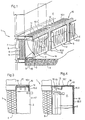
- Fig. 6 is a Fig. 5 corresponding representation of an alternative embodiment with a butt joint covered by a bar.
- Fig. 1 shows a part of a building with parapet and wall areas 1 and on the inside of these areas provided for space heating, filled with heating water heater 2.
- a floor ceiling of the building is designated by 4.
- the parapet and wall areas 1 have a structure intended for the use of solar energy, the details of which are only shown in the central wall element of the part of the parapet and wall areas 1 shown.
- An absorption layer 9, which absorbs the solar radiation from the air space 8 is arranged between a wall shell 6 on the inside of the building, which is designed as a heat insulation layer, and a wall shell 7 which is permeable to solar radiation and which contains an air space 8 as a heat insulation layer.
- the heat energy obtained in the absorption layer 9 from the solar radiation results in a heat flow directed outwards on the one hand, and a heat flow flowing through the wall shell 6 on the inside of the building and the wall surface 3 into the interior of the building (in each case on the right side of the outer wall 1 in the drawing).
- the heating elements 2 are in thermal contact with the inner wall surface 3.
- the heating elements 2 lie directly against the inner wall surface 3 and are supported on the floor ceiling 4 with feet 5.
- the heating elements 2 can also form the end wall of the wall shell 6 on the building side.
- the radiators 2 are connected to a heating water circuit, not shown in detail, in which the heating water is circulated by means of a circulating pump from parapet and wall areas with a high solar energy input to parapet and wall areas that are exposed to a low solar energy supply.
- the heating elements 2 are designed as radiators or convectors.
- the heating water forms a heat storage medium that can absorb heat directly from the wall shell 6 of the building with the thermal barrier coating. If this heat is not required for room heating, it can be fed to a domestic water reservoir via a heat exchanger.
- a cladding 10 is provided on the inside of the building, through which a convection space 11 through which the air of the interior of the building can flow is formed.
- the strength of the air flow flowing through the convection chamber 10 can be adjusted by means of adjustable flow devices.
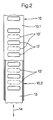
- the cladding 10 has a convection space 11 at the top that adjoins the inner wall surface 3 of the outer wall 1 Cover wall 10.1 with outlet openings 12 for the air flowing through the convection chamber 11.
- the flow devices adjusting the air flow are formed by suitable closure members 13 for these outlet openings 12.
- Such closure members 13 can be adjustable sliders, as in FIGS. 1, 2 and 3 or flaps (FIG.
- the closure members 13 being pulled out in the drawing in their position closing the outlet openings 12, in their position in which the outlet openings 12 are completely exposed 13 'are shown in dashed lines (Fig. 2).
- the adjustment of the closure members 13 takes place in the direction of the double arrows 14.
- the cladding 10 has a front wall 10.2 which is essentially parallel to the inner wall surface 3 and which adjoins the top wall 10.1 above and below the top wall 10.1 the convection chamber 11 towards the building interior except for im Floor area of the building interior provided openings 15 for the entry of air into the convection space 11 closes.
- the top wall 10.1 and the front wall 10.2 extend continuously over all radiators 2. In this case, as shown in FIGS.
- the front wall 10.2 can have a recess 16 for each radiator 2 in which the radiator 2 with its Building interior facing wall 17 is flush with the outer surface of the front wall 10.2 and with its upper edge and its two lateral edges closely adjoins the associated edges of the recess 16.
- the closure members 13 forming the flow devices have actuators, not shown in detail, which can be controlled outside and / or inside the building depending on selected climate values.
- climate values can be the outside temperature and the solar energy supply on the one hand and the inside temperature in the building interior on the other hand.
- sensors can be provided, which are also not shown in the drawing.
- the circulation pump can also be controlled as a function of the values recorded by the sensors.
- the lining 10 can carry a thermal insulation layer 18 on the inner surface facing the convection space 11, which is indicated in FIGS. 3 and 4 only by a thicker stroke width.
- radiators 2 and the posts or bars 19 are each thermally separated by an insulating intermediate layer 20.
- the butt joint 21 formed by the radiators 2 is by means of a strip 22 covered, which rests on seals 23, the radiators 2 and is screwed to the posts or bolts 19.
Landscapes
- Engineering & Computer Science (AREA)
- Physics & Mathematics (AREA)
- Life Sciences & Earth Sciences (AREA)
- Sustainable Development (AREA)
- Sustainable Energy (AREA)
- Thermal Sciences (AREA)
- Chemical & Material Sciences (AREA)
- Combustion & Propulsion (AREA)
- Mechanical Engineering (AREA)
- General Engineering & Computer Science (AREA)
- Building Environments (AREA)
Applications Claiming Priority (2)
| Application Number | Priority Date | Filing Date | Title |
|---|---|---|---|
| DE19614516A DE19614516C1 (de) | 1996-04-12 | 1996-04-12 | Anordnung zur Beeinflussung des zur Gebäudeinnenseite gerichteten Wärmetransports bei einem mit Solarenergie beheizbaren Gebäude |
| DE19614516 | 1996-04-12 |
Publications (2)
| Publication Number | Publication Date |
|---|---|
| EP0801276A2 true EP0801276A2 (fr) | 1997-10-15 |
| EP0801276A3 EP0801276A3 (fr) | 1999-03-03 |
Family
ID=7791109
Family Applications (1)
| Application Number | Title | Priority Date | Filing Date |
|---|---|---|---|
| EP97101744A Withdrawn EP0801276A3 (fr) | 1996-04-12 | 1997-02-05 | Bâtiment avec zones de parois ou d'appui utilisant l'énergie solaire |
Country Status (3)
| Country | Link |
|---|---|
| EP (1) | EP0801276A3 (fr) |
| DE (1) | DE19614516C1 (fr) |
| PL (1) | PL184989B1 (fr) |
Cited By (1)
| Publication number | Priority date | Publication date | Assignee | Title |
|---|---|---|---|---|
| CN103697531A (zh) * | 2013-12-17 | 2014-04-02 | 柳州市五环水暖器材经营部 | 一种挂壁多功能暖气片 |
Families Citing this family (2)
| Publication number | Priority date | Publication date | Assignee | Title |
|---|---|---|---|---|
| DE19737944A1 (de) * | 1997-08-30 | 1999-03-04 | Wilfrid Balk | Solarfassade |
| DE19805190A1 (de) * | 1998-02-10 | 1999-08-12 | Martin Merkler | Speicherheizkörper für solare Beheizung |
Citations (1)
| Publication number | Priority date | Publication date | Assignee | Title |
|---|---|---|---|---|
| WO1995010741A1 (fr) | 1993-10-13 | 1995-04-20 | Norsk Hydro A.S. | Structure de paroi exterieure pour batiments, notamment panneaux de lambris pour la zone d'appui de la paroi d'un batiment |
Family Cites Families (9)
| Publication number | Priority date | Publication date | Assignee | Title |
|---|---|---|---|---|
| DE2708128A1 (de) * | 1977-02-25 | 1978-08-31 | Nipp & Co Ernst | Fassadenelement fuer eine gebaeude- vorhangwand |
| US4237865A (en) * | 1979-03-02 | 1980-12-09 | Lorenz Peter J | Solar heating siding panel |
| DE2932628C2 (de) * | 1979-08-11 | 1985-04-11 | Prof. Dr.-Ing. Friedrich 3000 Hannover Haferland | Einrichtung zur Klimatisierung von Gebäuden |
| US4442826A (en) * | 1980-11-04 | 1984-04-17 | Pleasants Frank M | Prefabricated panel for building construction and method of manufacturing |
| DE3230639A1 (de) * | 1982-08-18 | 1984-02-23 | Fraunhofer-Gesellschaft zur Förderung der angewandten Forschung e.V., 8000 München | Waermeschutz und klimatisierung mit fassadenkollektoren |
| DE3507876A1 (de) * | 1985-03-06 | 1986-09-11 | Didier-Werke Ag, 6200 Wiesbaden | Verwendung von zementfreien vibriermassen auf basis von aluminiumoxid und/oder zirkoniumdioxid zur herstellung von verschleissteilen |
| DE3912095A1 (de) * | 1989-04-13 | 1990-10-18 | Johann B Pfeifer | Grossflaechenwaermetauscher |
| DE9116975U1 (de) * | 1990-04-28 | 1995-02-16 | Rud. Otto Meyer-Umwelt-Stiftung, 22047 Hamburg | Anlage zum Heizen und/oder Kühlen eines Gebäudes mit Solarenergie unter Verwendung von transparenter Wärmedämmung |
| DE9109213U1 (de) * | 1991-07-25 | 1992-11-19 | Bossert, Gerdi, 7730 Villingen-Schwenningen | Plattenelement |
-
1996
- 1996-04-12 DE DE19614516A patent/DE19614516C1/de not_active Expired - Fee Related
-
1997
- 1997-02-05 EP EP97101744A patent/EP0801276A3/fr not_active Withdrawn
- 1997-04-11 PL PL97319448A patent/PL184989B1/pl not_active IP Right Cessation
Patent Citations (1)
| Publication number | Priority date | Publication date | Assignee | Title |
|---|---|---|---|---|
| WO1995010741A1 (fr) | 1993-10-13 | 1995-04-20 | Norsk Hydro A.S. | Structure de paroi exterieure pour batiments, notamment panneaux de lambris pour la zone d'appui de la paroi d'un batiment |
Cited By (1)
| Publication number | Priority date | Publication date | Assignee | Title |
|---|---|---|---|---|
| CN103697531A (zh) * | 2013-12-17 | 2014-04-02 | 柳州市五环水暖器材经营部 | 一种挂壁多功能暖气片 |
Also Published As
| Publication number | Publication date |
|---|---|
| PL184989B1 (pl) | 2003-01-31 |
| PL319448A1 (en) | 1997-10-13 |
| EP0801276A3 (fr) | 1999-03-03 |
| DE19614516C1 (de) | 1997-10-09 |
Similar Documents
| Publication | Publication Date | Title |
|---|---|---|
| DE1301454B (de) | Raumkuehlgeraet | |
| EP0890800B1 (fr) | Radiateur a une ou a plusieurs plaques avec au moins deux sections différentes | |
| EP0177657B1 (fr) | Système pour assurer la demande d'énergie d'un local | |
| DE1604246A1 (de) | Verfahren und System zur Klimatisierung eines Gebaeudes | |
| EP0062297A2 (fr) | Installation de chauffage et de ventilation | |
| DE2621186C3 (de) | Vorrichtung zum Temperieren von außenliegenden Räumen eines Gebäudes | |
| DE19614516C1 (de) | Anordnung zur Beeinflussung des zur Gebäudeinnenseite gerichteten Wärmetransports bei einem mit Solarenergie beheizbaren Gebäude | |
| DE3312998A1 (de) | Gebaeudefassade zur nutzung der solarenergie | |
| EP0287106B1 (fr) | Chauffage pour un sauna | |
| DE19831918C2 (de) | Verfahren und Einrichtung zum Heizen oder Kühlen von vorwiegend geschlossenen Räumen | |
| DE3248226A1 (de) | Umlaufende einfassung fuer tueren oder fenster, sowie kastenbauteil, insbesondere rolladenkasten, zur verwendung oberhalb der einfassung | |
| DE1804281A1 (de) | Vorrichtung fuer Raumkonditionierung | |
| DE19614515C1 (de) | Anordnung zur Beeinflussung des zur Gebäudeinnenseite gerichteten Wärmetransports bei einem mit Solarenergie beheizbaren Gebäude | |
| DE3248227A1 (de) | Umlaufende einfassung fuer tueren oder fenster, sowie kastenbauteil, insbesondere rolladenkasten, zur verwendung oberhalb der einfassung | |
| DE1579777C (fr) | ||
| DE102007036143A1 (de) | Ein- oder mehrreihiger Heizkörper mit zumindest zwei verschiedenen ausgelegten Abschnitten | |
| DE102007036142A1 (de) | Ein- oder mehrreihiger Heizkörper mit zumindest zwei verschieden ausgelegten Abschnitten | |
| DE2323141A1 (de) | Verfahren und vorrichtung zum regeln der temperatur mittels eines stromes untertemperierter luft | |
| EP2990023A1 (fr) | Hybride de chauffage de cabine de traitement thermique | |
| DE1454614C3 (de) | Lüftungsgerät | |
| DE10320365B4 (de) | Kühldecke bzw. Kühlsegel mit Speicherfähigkeit | |
| DE1579777B2 (de) | Raumheizungsanlage mit waermespeicherofen | |
| DE69525672T2 (de) | Gebäudekonstruktionen und Verfahren zur Temperatursteuerung des Innenraums solcher Gebäude | |
| DE2307373C3 (de) | Elektrischer Speicherofen | |
| DE2940591C2 (de) | Zentralheizungsanlage |
Legal Events
| Date | Code | Title | Description |
|---|---|---|---|
| PUAI | Public reference made under article 153(3) epc to a published international application that has entered the european phase |
Free format text: ORIGINAL CODE: 0009012 |
|
| AK | Designated contracting states |
Kind code of ref document: A2 Designated state(s): AT BE CH DE LI NL SE |
|
| RBV | Designated contracting states (corrected) |
Designated state(s): AT BE CH DE LI NL SE |
|
| PUAL | Search report despatched |
Free format text: ORIGINAL CODE: 0009013 |
|
| AK | Designated contracting states |
Kind code of ref document: A3 Designated state(s): AT BE CH DE LI NL SE |
|
| 17P | Request for examination filed |
Effective date: 19990612 |
|
| 17Q | First examination report despatched |
Effective date: 20011218 |
|
| STAA | Information on the status of an ep patent application or granted ep patent |
Free format text: STATUS: THE APPLICATION IS DEEMED TO BE WITHDRAWN |
|
| 18D | Application deemed to be withdrawn |
Effective date: 20030902 |