EP0800923A2 - Mit einer Vielzahl von Elementen arbeitender Drucker und zugehöriges Justierverfahren - Google Patents
Mit einer Vielzahl von Elementen arbeitender Drucker und zugehöriges Justierverfahren Download PDFInfo
- Publication number
- EP0800923A2 EP0800923A2 EP97105733A EP97105733A EP0800923A2 EP 0800923 A2 EP0800923 A2 EP 0800923A2 EP 97105733 A EP97105733 A EP 97105733A EP 97105733 A EP97105733 A EP 97105733A EP 0800923 A2 EP0800923 A2 EP 0800923A2
- Authority
- EP
- European Patent Office
- Prior art keywords
- printing
- receiving medium
- dots
- printhead
- feeding
- Prior art date
- Legal status (The legal status is an assumption and is not a legal conclusion. Google has not performed a legal analysis and makes no representation as to the accuracy of the status listed.)
- Granted
Links
- 238000000034 method Methods 0.000 title claims description 32
- 238000012546 transfer Methods 0.000 claims description 40
- 238000003825 pressing Methods 0.000 claims description 11
- 230000002093 peripheral effect Effects 0.000 claims description 6
- 238000012840 feeding operation Methods 0.000 claims description 5
- 238000012545 processing Methods 0.000 description 23
- 239000006185 dispersion Substances 0.000 description 14
- 238000012360 testing method Methods 0.000 description 14
- 238000010586 diagram Methods 0.000 description 11
- 230000002411 adverse Effects 0.000 description 8
- 238000012544 monitoring process Methods 0.000 description 8
- 230000000694 effects Effects 0.000 description 7
- 230000003247 decreasing effect Effects 0.000 description 4
- 230000015572 biosynthetic process Effects 0.000 description 3
- 238000004140 cleaning Methods 0.000 description 3
- 238000004519 manufacturing process Methods 0.000 description 3
- 230000002829 reductive effect Effects 0.000 description 3
- 230000002441 reversible effect Effects 0.000 description 3
- 239000011159 matrix material Substances 0.000 description 2
- 230000000452 restraining effect Effects 0.000 description 2
- 238000004904 shortening Methods 0.000 description 2
- 238000001514 detection method Methods 0.000 description 1
- 230000003292 diminished effect Effects 0.000 description 1
Images


Classifications
-
- B—PERFORMING OPERATIONS; TRANSPORTING
- B41—PRINTING; LINING MACHINES; TYPEWRITERS; STAMPS
- B41J—TYPEWRITERS; SELECTIVE PRINTING MECHANISMS, i.e. MECHANISMS PRINTING OTHERWISE THAN FROM A FORME; CORRECTION OF TYPOGRAPHICAL ERRORS
- B41J2/00—Typewriters or selective printing mechanisms characterised by the printing or marking process for which they are designed
- B41J2/485—Typewriters or selective printing mechanisms characterised by the printing or marking process for which they are designed characterised by the process of building-up characters or image elements applicable to two or more kinds of printing or marking processes
- B41J2/505—Typewriters or selective printing mechanisms characterised by the printing or marking process for which they are designed characterised by the process of building-up characters or image elements applicable to two or more kinds of printing or marking processes from an assembly of identical printing elements
-
- G—PHYSICS
- G06—COMPUTING; CALCULATING OR COUNTING
- G06K—GRAPHICAL DATA READING; PRESENTATION OF DATA; RECORD CARRIERS; HANDLING RECORD CARRIERS
- G06K15/00—Arrangements for producing a permanent visual presentation of the output data, e.g. computer output printers
- G06K15/02—Arrangements for producing a permanent visual presentation of the output data, e.g. computer output printers using printers
- G06K15/10—Arrangements for producing a permanent visual presentation of the output data, e.g. computer output printers using printers by matrix printers
- G06K15/102—Arrangements for producing a permanent visual presentation of the output data, e.g. computer output printers using printers by matrix printers using ink jet print heads
- G06K15/105—Multipass or interlaced printing
Definitions
- the present invention relates to a multiple element printer conducting printing operation by relatively moving a printhead provided with a plurality of printing elements and a receiving medium in a main scan direction and in a sub scan direction, and a method of adjusting a multiple element printer.
- the present invention relates to a multiple element printer realizing high print density by controlling image printing operation of a plurality of printheads each including a plurality of printing elements.
- feed accuracy of the receiving medium and positional accuracy of a plurality of printing elements arranged at the printhead are pointed out as factors influencing on quality.
- the high density formation of the printing elements is actually limited.
- the high density formation is realized by arranging a plurality of printing elements at intervals each of a printing resolution multiplied by an integer in a direction of feeding a receiving medium (referred to as sub scan direction) and carrying out plural times of scanning in a direction of moving the printhead (referred to as main scan direction) and feeding of a receiving medium in the sub scan direction by a unit of a minimum resolution.
- the receiving medium is fed by 1 dot in the sub scan direction at every scanning of the printhead in the main scan direction.
- the dispersion is caused by a deviation in arrangement of the printing elements per se or is caused by a deviation in forming dots on receiving medium.
- the deviation in the print position is significantly manifested at portions of continuous print regions by one printing element coupled with portions of continuous print regions by other printing element whereby the image quality may be deteriorated.
- the amount of feed in the sub scan direction the amount of feed by 1 dot and the amount of feed by ⁇ (n-1)k+1 ⁇ dots are mixed.
- the feed accuracy of the receiving medium is dispersed depending on the amount of feed in the sub scan direction and therefore, when the amounts of feed in the sub scan direction of two kinds or more are mixed, the difference in the accuracy may influence on image quality and may deteriorate the quality.
- interlace printing method to reduce such a dispersion of printing elements and the difference in the feed accuracy.
- An interlace printing method is described in, for example, U.S. Patent No. 4,198,642.
- the interlace printing method is a method where a relationship between an interval k of printing elements and a number thereof is specified and a receiving medium is fed in the sub scan direction by a constant pitch.
- k and n are mutually prime with each other and the feed pitch is set to n by which the interlace printing can be realized.
- the printing elements printing contiguous lines are made to differ from each other whereby a disturbance in image quality derived from the positional dispersion of the printing elements is diminished and the deviation in the feed accuracy of a total of a print region is made uniform.
- a disturbance in image quality derived from the positional dispersion of the printing elements is diminished and the deviation in the feed accuracy of a total of a print region is made uniform.
- Figure 21 is an explanatory view for explaining problems in the conventional interlace printing method.
- Figure 21 shows a case where the interlace printing is carried out by using a printhead conducting the operation illustrated by Figure 20 and is an example of a case where a resolution of a drive source such as a motor or the like is poor and therefore, the feed accuracy of the receiving medium is not permissible.
- an error of (- ⁇ ) is caused with respect to n dots of the feed amount of a receiving medium, the amount of feed at one time is shortened.
- the error of the feed amount in the negative direction has been described in the above example, the streaks are also manifested in the case where the error is caused in the positive direction.
- the conventional multiple element printers are constructed as described above and therefore, even if the interlace printing is carried out, when the resolution of the drive source such as a motor or the like is poor and therefore, the feed accuracy of the receiving medium is not permissible, or the attachment accuracy of the printhead is poor, the streaks emerge in printed images and disturbances in the image quality are caused.
- the high density printing system or the interlace printing system is conducted by adopting the plural time scanning and the feed by a unit of a minimum resolution and therefore, a very fine deviation in the print position in the sub scan direction of the printing element (that is caused by a dispersion in the characteristic of the printing elements, a deviation in arrangement of the printing elements, a deviation in printing dots on the receiving medium, or the like) or a deviation in feed accuracy of the receiving medium (that is caused by the mixed feed amounts of two kinds or more in the sub scan direction) which is significantly manifested at coupled portions of continuous print regions of the printing elements, deteriorates the image quality.
- the present invention has been carried out in order to resolve the above-described problems and it is a first object of the present invention to provide a multiple element printer capable of obtaining images having stable printing quality and where even if an error occurs in feed accuracy of a receiving medium or in an accuracy of attaching a printhead, adverse influence thereof is not manifested in printed images. It is a second object of the present invention to provide a method of adjusting a multiple element printer capable of easily adjusting a multiple element printer for achieving excellent image quality.
- a multiple element printer comprising:
- a multiple element printer according to the first aspect, further comprising:
- a multiple element printer according to the second aspect, further comprising:
- a multiple element printer according to the second aspect, further comprising:
- a multiple element printer comprising:
- a multiple element printer according to the first or the fifth aspect, further comprising:
- a multiple element printer comprising:
- the dot diameter adjusting means adjusts the sizes of the dot diameters printed by the 1-th one and the N-th one of the printing elements as well as sizes of dot diameters printed by a 2-th one and a (N-1)-th one of the printing elements.
- a multiple element printer comprising:
- a multiple element printer comprising:
- a multiple element printer according to the eleventh or the twelfth aspect, wherein the first driving means uses a drum capable of mounting the receiving medium and rotated with an axis as a center.
- a fourteenth aspect of the present invention there is provided a multiple element printer comprising:
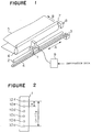
- Figure 1 is a constitutional view showing a multiple element printer according to Embodiment 1.
- numeral 1 designates an ink jet head (hereinafter printhead) arranged with a group of printing elements where a plurality of nozzles ejecting ink are installed as the printing elements
- numeral 2 designates a shaft for supporting the printhead 1 and guiding the printhead 1 in an arrow mark A direction (hereinafter, referred to as main scan direction) when the printhead is moved
- numeral 3 designates a scan motor as a second driving means for moving the printhead
- numeral 4 designates a drive belt for transmitting the drive force of the scan motor 3 to the printhead
- numerals 6 and 7 are rollers for supporting a receiving medium 5 and feeding the receiving medium 5 in an arrow mark B direction (hereinafter, referred to as sub scan direction)
- numeral 8 designates a feed motor as a first driving means for driving the roller 6 for driving the receiving medium 5
- numeral 9 designates a control unit for driving the printhead
- N of nozzles as the printing elements for ejecting ink to the receiving medium 5 are arranged at the printhead 1 along the sub scan direction. Any methods of ejecting ink may be used; for example, methods for ejecting ink by generating a pressure by using an electricity-mechanical converting element such as a piezoelectric element, an electricity-heat converting element where the pressure is applied on ink by heated steam or the like, and so on are available.
- the control unit 9 generates drive signals for actually driving the respective nozzles in the printhead 1 based on information data expressing image or letter information and output them to the printhead 1 by which ink is made to eject onto the receiving medium 5 whereby printing image is formed.
- the scan motor 3 and the printhead 1 are connected by the drive belt 4 and when the control unit 9 drives the scan motor 3, the printhead 1 is moved in the main scan direction while ejecting ink by being guided by the shaft 2 whereby one operation of image printing is conducted.
- the control unit 9 successively drives the feed motor 8, progresses the receiving medium 5 in the sub scan direction by a constant distance (P dots) and returns the printhead 1 to the initial position. Further, the control unit 9 makes the printhead 1 eject ink while moving it by which a second operation of image printing is carried out. Thereafter, the operation of feeding the receiving medium by the constant distance (P dots) after finishing the one operation of image printing, is repeated until all the information data are printed.
- Figure 2 is a constitutional view showing the printhead of the present invention where an arrangement of nozzles is shown.
- notations 10a through 10f designate respective nozzles. Defining an interval between contiguous nozzles as k (dots) and a number of nozzles as N, the following relationships are satisfied among k, N and the amount of feed P in one feeding operation of the above-described receiving medium 5.
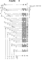
- Figure 3 is a constitutional diagram showing the control unit 9 shown by Figure 1.
- numeral 11 designates a data forming circuit having a storing means for storing information data expressing image or data information
- numeral 12 designates a processing circuit as a processing means for selecting and reading as data 16 the information data in accordance with the arrangement of the nozzles in the printhead 1 from the data forming circuit 11 and outputting printing data 16a through 16f in accordance with the respectives of the nozzles 10a through 10f
- numeral 13 designates a nozzle driving circuit as a signal generating means for generating drive signals 17a through 17f for actually driving the nozzles 10a through 10f based on the printing data 16a through 16f
- numeral 14 designates a printing element drive signal forming means comprising the processing circuit 12 and the nozzle driving circuit 13
- numeral 15 designates an administration unit as a controlling means for controlling the scan motor 3 and the feed motor 8 and starting up the data forming circuit
- the control unit 9 When the information data is inputted, the information data is stored in the data forming circuit 11.
- the administration unit 15 outputs the start signal 18 to the data forming circuit 11, the data forming circuit 11 successively reads the information data in correspondence with 1 line of pixels which are to be printed by the respectives of the nozzles 10a through 10f at the printhead 1 and outputs the information data to the processing circuit 12 as the data 16a through 16f.
- the data 16a through 16f are inputted to the processing circuit 12, the data 16a through 16f are distributed in respect to the respective nozzles and when the instruction signal 19 is inputted from the administration unit 15, the printing data 16a through 16f are outputted to the nozzle driving circuit 13.
- the printing data 16a through 16f are data only representing whether ink is to be ejected or not and when ink is to be ejected, "1" is outputted and when ink is not to be ejected, "0" is outputted.
- the instruction signal 19 is a signal of 6 bits where the lowest bit corresponds to the nozzle 10a and the highest bit corresponds to the nozzle 10f.
- the printing data in correspondence with the data 10a through 10f are outputted to the nozzles where "1" is described in the instruction signal 19 and the printing data prohibiting to eject ink are outputted to the nozzles where "0" is described in the instruction signal 19, with respect to all the data of 1 line.
- the printing data 16a in correspondence with the nozzle 10a always outputs "0" to pixels of even ordinal numbers and the printing data 16f in correspondence with the nozzle 10f always outputs "0" to pixels of odd ordinal numbers.
- the nozzle driving circuit 13 When the printing data 16a through 16f are inputted to the nozzle driving circuit 13, the nozzle driving circuit 13 generates the drive signals 17a through 17f for actually driving the respective nozzles in accordance with values of the data and outputs them to the nozzles 10a through 10f.
- the administration unit 15 outputs the start signal 18 to the data forming circuit 11, successively operates the scan motor 3 and moves the printhead 1 in the main scan direction.
- the administration unit 15 detects the amount of movement of the printhead 1 in the main scan direction by monitoring a rotational angle of the scan motor 3 and when the printhead 1 is moved to a position on the receiving medium 5 where a dot is initially formed, the administration unit 15 outputs the start signal 19 to the processing circuit 12 such that the printing data 16a through 16f are outputted to the nozzle driving circuit 13.
- the nozzle driving circuit 13 generates the drive signals 17a through 17f for actually driving the nozzles 10a through 10f in accordance with the printing data outputted from the processing circuit 12 and outputs them to the printhead 1 by which the respective nozzles carries out the one operation of printing 1 line.
- the administration unit 15 drives the feed motor 8, moves the receiving medium 5 in the sub scan direction by 5 lines, returns the printhead 1 to the initial position and repeats the above-described printing operation again.
- Figure 4 is an explanatory view for explaining printing operation of the multiple element printer according to Embodiment 1.
- N 6 in respect of the number of the nozzles
- notation d represents printed dots printed by the respective nozzles
- notation t designates a number of scan.
- a printed dot contiguous to other printed pixel is printed by a nozzle that is always different from a nozzle for printing the other printed pixel by which a print result similar to that in the interlace printing is provided.
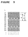
- Figure 5 is an explanatory view for explaining the operation of preventing occurrence of streaks by the multiple element printer according to Embodiment 1 where a print result when an error is caused in the amount of feeding the receiving medium 5 in the sub scan direction, is shown.
- similar reasoning is applicable also in the case where the actual amount of feed is larger than the feed amount P of the receiving medium 5 whereby the occurrence of streaks can also be prevented.
- FIG. 6 is a constitutional diagram showing a controlling unit of a multiple element printer according to Embodiment 2 of the present invention where notations the same as those in Figure 3 represent the same or the corresponding portions and an explanation thereof will be omitted.
- notation 13a designates a nozzle driving circuit where in generating drive signals 21a through 21f for actually driving the nozzles 10a through 10f based on the printing data 16a through 16f, voltage values of the drive signals 21a through 21f are changed in accordance with inputted set values and thereafter, the voltage values are outputted and notation 14a designates a printing element drive signal forming means comprising the processing circuit 12 and the nozzle driving circuit 13a and numeral 20 designates a dot diameter setting circuit for outputting set values for changing the voltage values of the drive signal 21a and 21f outputted by the nozzle driving circuit 13a.
- a series of operations from inputting the information data to the data forming circuit 11 to outputting the printing data 16a through 16f from the processing circuit 12 to the nozzle driving circuit 13a are the same as those in Embodiment 1.
- the driving signals 21a through 21f for actually driving the respective nozzles in accordance with the data values are generated and outputted to the nozzles 10a through 10f.
- the nozzle driving circuit 13a receives the set values in accordance with, for example, values of variable resistors installed to the dot diameter setting circuit 20 and voltage values of the drive signal 21a of the nozzle 10a and the drive signal 21f of the nozzle 10f are made different from the other drive signals 21b through 21e based on the given set values and outputted.
- the drive signals 21a through 21f outputted from the nozzle driving circuit 13a are outputted to the printhead, the nozzle 10a through 10f eject ink in accordance with the voltage values of the drive signals in correspondence with the respective nozzles by which dots are printed on the receiving medium 5.
- the nozzles 10a and 10f print dots with sizes of diameters of the printed dots different from sizes of diameters of dots printed by the other nozzles.
- the other operations are the same as those in Embodiment 1.
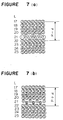
- Figures 7(a) and 7(b) are explanatory views for explaining printing operation of the multiple element printer according to Embodiment 2 of the present invention in which a result of the case where the printing operation is carried out by changing the dot diameters when an error is caused in the amount of feeding the receiving medium.
- Figure 7(a) shows the case where the actual amount of feed is shorter than the regular amount of feed P by ⁇ .
- Figure 7(b) shows the case where the actual amount of feed is longer than the regular amount of feed P by ⁇ .
- the set values are changed by printing information data for adjusting image quality and adjustment of the sizes of the dot diameters is finished when the occurrence of streaks is dispensed with.
- the occurrence of streaks due to an error in feeding the receiving medium 5 in the sub scan direction of the multiple element printer can be prevented by which printed images having high quality can be obtained.
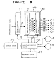
- Figure 8 is a constitutional diagram showing another control unit in the multiple element printer according to Embodiment 3 of the present invention where notations the same as those in Figure 3 designate the same or the corresponding portions and an explanation thereof will be omitted.
- notation 13b designates a nozzle driving circuit in which in generating drive signals 23a through 23f for actually driving the nozzles 10a through 10f based on the printing data 16a through 16f, voltage values of the drive signals 23a and 23f are changed in accordance with inputted set values and outputted
- notation 14b designates a printing element drive signal forming means comprising the processing circuit 12 and the nozzle driving circuit 13b
- numeral 24 designates an input unit for instructing sizes of dot diameters
- numeral 25 designates a storing unit storing a plurality of the set values and the other constitutions are the same those in Embodiment 2.
- a series of operations from inputting the information data to the data forming circuit 11 to outputting the printing data 16a through 16f from the processing circuit 12 to the nozzle driving circuit 13b are the same as those in Embodiment 1.
- the drive signals 23a through 23f for actually driving the respective nozzles in accordance with data values are generated and outputted to the nozzles 10a through 10f.
- set values are inputted from the administration unit 15 to the nozzle driving circuit 13b and voltage values of the drive signal 23a of the nozzle 10a and the drive signal 23f of the nozzle 10f are changed from those of the other drive signals 23b through 23f based on the given set values and outputted.
- the drive signals 23a through 23f outputted from the nozzle driving circuit 13b are inputted to the printhead, the nozzles 10a through 10f eject ink in accordance with the voltage values of the drive signals in correspondence with the respective nozzles whereby dots are printed on the receiving medium.
- the input unit 24 may have a simple constitution capable of inputting numerical values from outside such as that of a dip switch and numerical values instructing desired sizes of dot diameters are set in the input unit 24.
- a numerical value "0" when instructed, it signifies that the outputting operation is conducted without changing the sizes of the dot diameters.
- the administration unit 15 initially reads the information of the input unit 24.
- the storing unit 25 is consisted by an involatile memory where a plurality of set values for changing the sizes of the dot diameters are stored.
- the administration unit 15 reads the plurality of set values from the storing unit 25 based on the values of the input unit 24 and set the values to the nozzle driving circuit 13b.
- the other operations are the same as those in Embodiment 2.
- the occurrence of streaks due to an error in feeding the receiving medium 5 in the sub scan direction can be restrained in the multiple element printer by constituting the multiple element printer as described above by which printed images having high quality may be achieved and the adjusting operation for preventing the occurrence of streaks can simply be executed.
- FIG. 9 is a flowchart showing a method of adjusting a multiple element printer according to Embodiment 4 of the present invention where contents of respective steps are described in steps S1 through S12.
- the constitution of the multiple element printer and the constitution of the control unit in Embodiment 4 are the same as those in Embodiment 3.
- step S1 receives instruction of test printing from an operation panel, not illustrated, image data for test printing is written to the data forming circuit 11 as test data (step S1) and the receiving medium is fed (step S2).
- step S3 set values of initial sizes of dot diameters are read from the storing unit 25 (step S3) and are set to the nozzle driving circuit (step S4).
- step S8 an operation of printing the test data on the receiving medium 5 is conducted in steps of S5 through S8.
- the operation of the image printing is the same as that in Embodiment 3.
- step S9 the receiving medium 5 is fed by a constant amount for printing successive test data (step S9).
- step S10 whether the test printing has been finished is determined in step S10.
- step S12 the next set value is read from the storing unit 25 (step S12) and the steps of S4 through S8 from setting the values to the nozzle driving circuit 13b to finishing the printing of the predetermined number of lines, are repeated again.
- step S10 the receiving medium 5 is discharged (step S11) whereby the test printing is finished.
- a plurality of test print samples where the dot diameters are changed can be obtained on one sheet of the receiving medium 5 in one operation. Further, the set values in respect of the sizes of the dot diameters are set in the order of numerical values instructed to the input unit 24. Accordingly, when the number of the sample having the best image quality among the plurality of obtained test printing samples, is instructed to the input unit 24, excellent printing is always carried out in the actual image printing, the operation of adjusting print quality can efficiently be performed and images having excellent print quality can simply be provided.
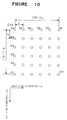
- FIG. 10 is a constitutional diagram showing a printhead of a multiple element printer according to Embodiment 5 of the present invention where notation Dxy represents a nozzle and nozzles D11 through D66 are installed in a printhead.
- the nozzles are arranged in a matrix in which an interval between contiguous nozzles in the sub scan direction is designated by notation k (dots), an interval between contiguous nozzles in the main scan direction is designated by notation j (dots), a number of the nozzles in the sub scan direction is designated by notation N and a number of the nozzles in the main scan direction is designated by notation M.
- an amount of feeding the receiving medium 5 in one motion is designated by P (dots) and a distance for moving the printhead in the main scan direction after finishing one dot until a successive dot is formed in the case where one of the nozzles forms dots by ejecting ink onto the receiving medium 5, is designated by notation Q (dots).
- P dots
- Q dots
- the components of the pairs may be the same as each other or different from each other.
- the constitution of the printhead and the constitution of other portions of the multiple element printer are same as those in Embodiment 1 except the operation of the control unit.
- the image printing is conducted by moving the printhead in the main scan direction while ejecting ink onto the receiving medium 5 based on information data expressing image or letter information.
- the printhead 1 is moved in a continuous operation at a constant speed.
- the other operations are the same as those in Embodiment 1.
- Figures 11(a) and 11(b) are explanatory diagrams for explaining the printing operation of the multiple element printer according to Embodiment 5 of the present invention in which a printing result in the main scan direction when the printing operation is conducted by the printhead shown by Embodiment 5, is illustrated.
- Figure 11(a) is an explanatory view for explaining the printing operation of one row of a group of nozzles, that is, nozzles of D16 through D66 illustrated by Figure 10.
- notation m designates a printed dot that is printed by each of the nozzles
- notation T designates a number of ejecting ink in the main scanning.
- Dots are formed also in the main scan direction similar to the above-described printing operation in the sub scan direction.
- the first nozzle and the sixth nozzle print the same position in the main scan direction also with respect to the main scan direction similar to the printing operation in the sub scan direction.
- the first nozzles and the sixth nozzles in the main scan direction can print dots alternately at the same positions.
- the printing speed in one main scanning operation can be accelerated and a high-speed printing device can be obtained by constituting the multiple element printer as described above. Further, the printing operation in the main scan direction is conducted similar to that in the sub scan direction and therefore, even if an error is caused in the moving speed of the printhead, the continuity of the printed dots in the main scan direction is not deteriorated, the occurrence of streaks can be prevented and further, images having stabilized high image quality can be obtained.
- the multiple element printer is naturally adaptable to color printing.
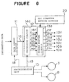
- FIG. 12 is a constitutional diagram showing a multiple element printer according to Embodiment 6 of the present invention.
- notation 1a designates a printhead having a plurality of nozzles for ejecting ink as printing elements
- numeral 26 designates a print roller as an intermediate transfer medium where printed dots are formed by the printhead 1
- numeral 27 designates a transfer roller that is a transfer means for transferring a receiving medium 31 and transferring the dots formed on the print roller 26 to the receiving medium
- notations 28a and 28b designate feed rollers for feeding the receiving medium
- notations 29(a) and 29(b) designate eject rollers for ejecting the receiving medium
- numeral 30 designates a cleaning unit for absorbing ink remaining on the above-described print roller 26
- numeral 31 designates the receiving medium
- numeral 32 designates a control unit for driving the printhead 1 to eject ink based on information data expressing
- N of nozzles as printing elements for ejecting ink to the receiving medium 31 are arranged in the printhead 1a. Any methods may be selected in respect of methods of ejecting ink, for example, there are methods of ejecting ink by generating a pressure by using an electricity-mechanical converting element such as a piezoelectric element, a electricity-heat converting element whereby the pressure is applied on ink by heated steam or the like.
- the control unit 32 generates drive signals for actually driving the respective nozzles in the printhead 1 based on information data expressing image or letter information, outputs the drive signals to the printhead 1 and ejects ink on the surface of the print roller 26 whereby printed images are formed.
- control unit 32 drives a scan motor, not illustrated, for moving the printhead 1, the printhead 1 is moved in C direction (main scan direction) illustrated in the drawing while ejecting ink by which one operation of image printing is conducted.
- the control unit 32 drives a driving motor, not illustrated, for rotating the print roller 16 by which the print roller 26 is rotated in D direction illustrated in the drawing by an angle corresponding to a constant distance (P dots) on the periphery and returns the printhead 1 to the initial position.
- the control unit 32 makes the printhead 1 eject ink while moving the printhead 1 again, by which a second image printing operation is conducted. Thereafter, the operation of rotating the print roller 26 by the angle corresponding to the constant distance (P dots) on the periphery after finishing the one image printing operation and these operations are repeated until printing of all the information data has been finished.
- the constitution of the printhead 1 and the method of printing dots on the surface of the print roller 26 are the same as those in Embodiment 1 and printed images similar to those in Embodiment 1 are formed on the surface of the print roller 26.
- the receiving medium 31 is fed by the feed rollers 28a and 28b and is transferred between the print roller 26 and the transfer roller 27.
- the transferred receiving medium 31 is transferred in an arrow mark E direction at a speed the same as the peripheral speed of the print roller 26 and in synchronism with the print roller 26 by the same pitch of P dots by the print roller 26 and the transfer roller 27.
- the printed dots formed on the print roller 26 are transferred onto the receiving medium 31 by pressing the transfer roller 27 to the receiving medium 31, final printed dots 33 are formed and the receiving medium is ejected by the eject rollers 29a and 29b.
- a portion of the surface of print roller 26 where the printed dots have been transferred onto the receiving medium 31, are cleaned in respect of the surface at the cleaning unit 30 and dots are formed again by the printhead 1a.
- the printed dots are formed once on the surface of the print roller 26 by ejecting ink and thereafter, the dots are transferred onto the receiving medium 31 by pressing the transfer roller 27 to the receiving medium 26. Accordingly, the image printing onto the receiving medium 31 can firmly be performed by the pressing force even in the case where ink having poor absorbability in respect of the receiving medium 31 is used. As a result, an effect capable of diversifying choice of ink for obtaining printed image having high image quality, is achieved.
- the printhead 1 where the printing elements are arranged in one row in Embodiment 6 as an example, the printhead 1 is not limited thereto but a printhead where printing elements are arranged in a matrix may be used.
- Figure 13 is a constitutional view showing a printhead 34 of a multiple element printer according to Embodiment 7 of the present invention.
- numeral 34 designates a printhead having a plurality of nozzles for ejecting ink as printing elements
- notations 35a through 35e designate respective nozzles as printing elements.
- k and N are positive integers mutually prime with each other.
- Figure 14 is a constitutional view showing a multiple element printer according to Embodiment 7 of the present invention where notations the same as those in Figure 3 designate the same or the corresponding portions and an explanation thereof will be omitted.
- notation 12c designates a processing circuit as a processing means for reading data 16 by selecting information data in accordance with arrangement of the nozzles in the printhead 34 from the data forming circuit 11 and outputting printing data 44a through 44c in correspondence with the respective nozzles 35a through 35e
- notation 13c designates a nozzle driving circuit for generating drive signals 45a through 45e for actually driving the nozzles 35a through 35e based on the printing data 44a through 44e
- notation 14c designates a printing element drive signal forming means comprising the processing circuit 12c and the nozzle driving circuit 13c
- numeral 39 designates an adjusting circuit as a dot diameter adjusting means for outputting output signals 46a through 46e to the nozzles 35a through 35e by changing voltage values of the drive signals 45a and 45
- the data is stored in the data forming circuit 11.
- the administration unit 15c outputs the start signal 18c to the data forming circuit 11
- the data forming circuit 11 successively reads the information data in correspondence with 1 line of dots which are to be printed by the respective nozzles 35a through 35e at the printhead 34 and outputs the information data to the processing circuit 12c as the data 16.
- the data 16 is inputted to the processing circuit 12c
- the data 16 is distributed in accordance with the respective nozzles and outputted as the printing data 44a through 44e to the nozzle driving circuit 13c when the instruction signal 19c is inputted from the administration unit 15c.
- the printing data 44a through 44e are data only showing whether ink is to be ejected or not and "1" is outputted when ink is to be ejected and "0" is outputted when ink is not to be ejected.
- the instruction signal 19c is a signal of 5 bits where the lowest bit corresponds to the nozzle 35a and the highest bit corresponds to the nozzle 35e, respectively.
- Printing data in correspondence with the data 16 is outputted to nozzles where "1" is described by the instruction signal 19c and printing data prohibiting to eject ink to all of 1 line of dots is outputted to nozzles where "0" is described thereby.
- the drive signal 45a through 45e for actually driving the respective nozzles in accordance with data values are generated and outputted.
- Certain adjust values are given from outside to the adjusting circuit 39 by, for example, variable resistors.
- the drive signals 45a through 45b are inputted to the adjusting circuit 39, the voltage values of the drive signal 45a of the nozzle 35a and the drive signal 45e of the nozzle 35e are changed based on the given adjust values and the other drive signals 45b through 45d stay with the voltage values as they are by which the partially modified drive signals 45a through 45e are outputted as the output signals 46a through 46e.
- the signals 46a through 46e outputted from the adjusting circuit 39 are inputted to the printhead 34, ink is ejected from the nozzles 35a through 35e in accordance with voltage values of the drive signals in correspondence with the respective nozzles and dots are printed on the receiving medium.
- the printing operation is conducted with sizes of dot diameters printed by the nozzles 35a and 35e different from sizes of dot diameters printed by the other nozzles.
- the administration unit 15c outputs the start signal 18c to the data forming circuit 11, successively operates the scan motor 3 and moves the printhead 34 in a constant direction (main scan direction).
- the administration unit 15c detects the amount of transfer of the printhead 34 in the main scan direction by monitoring a rotational angle of the scan motor 3 and outputs the instruction signal 19c to the processing circuit 12c such that when the printhead 34 is moved to a position where a dot is initially formed, the printing data 44a through 44e are outputted to the nozzle driving circuit 13c.
- the nozzle driving circuit 13c generates the drive signals 45a through 45e for actually driving the nozzles 35a through 35e in accordance with the printing data outputted from the processing circuit 12c and outputs the signals to the printhead 34 by which the respective nozzles carry out an operation of printing 1 line of dots.
- the interlace printing as shown by Figure 22 can be executed by carrying out the above-described printing operation.
- the continuity of printed dots in the sub scan direction is lost whereby streaks are formed and image quality is deteriorated.
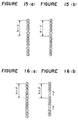
- Figure 15(b) shows an example of printing dots in the case where sizes of dot diameters of dots printed by the first nozzle and the fifth nozzle are made larger than sizes of dot diameters printed by the other nozzles by giving adjust values whereby occurrence of streaks is effectively prevented by enlarging the sizes of the dot diameters.
- Figure 16(b) shows an example of printing dots in the case where the sizes of the dot diameters of the dots printed by the first nozzle and the fifth nozzle are made smaller than the sizes of the dot diameters printed by the other nozzles by giving adjust values by which occurrence of streaks is prevented by decreasing the sizes of the diameters.
- set values are changed while printing information data for adjusting image quality and the adjustment of the sizes of the dot diameters is finished when the occurrence of streaks is dispensed with.
- Embodiment 7 Although an explanation has been given of Embodiment 7 with an example of the ink jet head for ejecting ink as a group of printing elements, a group of printing elements using a thermal head may be used.
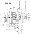
- Figure 17 is a constitutional view showing a multiple element printer according to Embodiment 8 of the present invention where notations the same as those in Figure 14 designate the same or the corresponding portions and an explanation thereof will be omitted.
- numeral 49 designates an adjusting circuit as a dot diameter adjusting means in which with respect to the drive signals 45a through 45e, voltage values of the drive signals 45a and 45e are changed in accordance with inputted first set values and voltage values of the drive signals 45b and 45d are changed in accordance with inputted second set values whereby output signals 50a through 50e are outputted to the nozzles 35a through 35e and other constitutions are the same as those in Embodiment 7.
- Two kinds of adjust values are given from outside to the adjusting circuit 49 by, for example, variable resistors as first set values and second set values.
- the drive signals 45a through 45e are inputted to the adjusting circuit 49, the voltage values of the drive signal 45a of the nozzle 35a and the drive signal 45e of the nozzle 35e are changed based on the given first set values and the voltage values of the drive signal 45b of the nozzle 35b and the drive signal 45d of the nozzle 35d are changed based on the second set values and the voltage value of the other drive signal stays as it is and the drive signals 45a through 45e are outputted as output signal 50a through 50e.
- the nozzles 35a through 35e eject ink in accordance with the voltage values of the drive signals in accordance with the respective nozzles by which dots are printed on the receiving medium.
- a printing operation is conducted with sizes of diameters of dots printed by the nozzles 35a, 35b, 35d and 35e different from a size of a dot diameter of a dot printed by the other nozzle.
- the nozzle 35a and the nozzle 35e share the same size of the dot diameter and the nozzle 35b and the nozzle 35d share the same size of the dot diameter that is different from the size of the dot diameter described immediately above.
- the other operations for conducting image printing are the same as those in Embodiment 7.
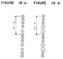
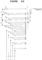
- the interlace printing as shown by Figure 20 can be conducted by executing the above-described printing operation.
- the interlace printing shown by Figure 20 when an error is caused in the amount of feeding the receiving medium in the sub scan direction, the continuity of the printed dots in the sub scan direction is lost whereby streaks are formed and image quality is deteriorated.
- Figure 18(b) shows an example of printing dots in the case where sizes of dot diameters of dots printed by the first nozzle and the fifth nozzle are enlarged and sizes of dot diameters of dots printed by the second nozzle and the fourth nozzle respectively contiguous to the dots printed by the first nozzle and the fifth nozzle, are conversely decreased.
- the sizes of the dot diameters of the dots printed by the first nozzle and the fifth nozzle are enlarged, portions thereof overlapping with the contiguous dots are increased which may become sources of occurrence of new streaks.
- the occurrence of streaks can effectively be prevented by adjusting the sizes of the dot diameters in respect of the contiguous dots in the reverse direction.
- the occurrence of streaks can be prevented even in the case where an error is caused in the feed accuracy of the receiving medium 5 and the accuracy of installing the printhead 34 by constituting the multiple element printer executing the interlace printing as described above by which adverse influence thereof is restrained in respect of printed images and images having further stabilized image quality can be obtained.
- a multiple element printer in Embodiment 9 of the present invention there are arranged a plurality of printheads, for example, printheads 1a and 1b each having as printing elements a plurality of ink jet nozzles ejecting ink to a receiving medium by a pressure generated by an electricity-mechanical converting element (piezoelectric element or the like) or a electricity-heat converting element (ink pressurizing element in use of heat or the like) satisfying the following conditions.
- an electricity-mechanical converting element piezoelectric element or the like
- electricity-heat converting element in use of heat or the like
- the head supporting/guiding shaft 2 supports the respective printheads 1a and 1b and guides them in the main scan direction (arrow mark A).
- the scan motor 3 transmits a drive force via the drive belt 4 in accordance with a drive signal 106 inputted from a control means 9 by which the respective printheads 1a and 1b are moved in the main scan direction (arrow mark A). Further, a signal 107 detecting the amount of movement of the printheads 1a and 1b in the main scan direction by monitoring a rotational angle by, for example, a rotary encoder or the like, is outputted to the control means 9.
- the feed rollers 6 and 7 are driven by the feed motor 8, support the printing medium 5 and moves it in the sub scan direction (arrow mark B).
- the feed motor 8 rotates the feed rollers 6 and 7 in accordance with a drive signal 108 inputted from the control means 9.
- high-speed printing can be performed by increasing the amount of feed of the printheads in the sub scan direction by a unit feed amount of the printhead multiplied by the number of the printheads.
- the present invention lowers fabrication yield and achieves reduction in cost without adopting a printing element number increase system by high-density formation of the printing elements or prolongation of the printheads.
- the multiple element printer in accordance with Embodiment 9 adopts a system of driving the respective printing elements of the printheads (high-density printing system by controlling printing operation).
- control means 9 successively reads information data corresponding to 1 line of dots and arrangement of nozzles to be printed by the nozzles 10a through 10f and 11a through 11f included in the printheads 1a and 1b in accordance with a start signal 103 issued by an administration unit 93 to a data forming unit 91 storing inputted information data 100 and outputs the information data as selection data 101a and 101b.
- drive signal forming units 92a and 92b output the inputted selection data 101a and 101b by distributing them in respect of the nozzles in accordance with instruction signals 104a and 104b issued by the administration unit 93.
- the administration unit 93 outputs a start signal 103 to the data forming unit 91, outputs a signal 106 for driving the scan motor 3, inputs a signal 107 for detecting the amount of movement of the printheads 1a and 1b in the main scan direction by monitoring the rotational angle of the scan motor, and outputs the instruction signals 104a and 104b for instructing to which nozzles ink is to be ejected to drive signal forming units 92a and 92b, when the printheads 1a and 1b are moved to initial dot forming positions on the receiving medium 5.
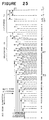
- the instruction signals 104a and 104b are signals each of 5 bits where the lowest bits correspond to the nozzles 10a and 11a and the highest bits correspond to the nozzles 10e and 11e and instruct the nozzles corresponding to the bit "1" or "0" to eject or not to eject ink. Further, the administration unit 93 outputs a signal 108 for driving the feed motor 8 by which the receiving medium 5 is moved in the sub scan direction by 10 dots and the printheads 1a and 1b are returned to initial positions. The above-described control of printing operation is repeated until printing of all the information data has been finished.
- a printed dot contiguous to a printed dot d 1 or d 2 in the sub scan direction is printed by a nozzle that is always different from a nozzle for printing the printed dot d 1 or d 2 by which a print result the same as that in interlace printing is provided.
- Embodiment 9 of the present invention illustrated by Figure 22 such that the control means 9 inputs the signal 107 for detecting the amount of movement of the printheads 1a an 1b in the main scan direction by monitoring the rotational angle of the scan motor and outputs the instruction signals 104a and 104b when the printheads 1a and 1b are moved to the initial dot forming positions on the receiving medium 5.
- control means 9 may be replaced by a control means 9a which measures the inputted detection signal 106 and outputs the instruction signal 104a and 104b at every time where the printheads 1a and 1b are moved by P dots (10 dots) in the main scan direction and printheads 1a and 1b arranged with the printing elements in the main scan direction instead of the sub scan direction, may be arranged in the main scan direction instead of the sub scan direction.
- a control means 9a which measures the inputted detection signal 106 and outputs the instruction signal 104a and 104b at every time where the printheads 1a and 1b are moved by P dots (10 dots) in the main scan direction and printheads 1a and 1b arranged with the printing elements in the main scan direction instead of the sub scan direction, may be arranged in the main scan direction instead of the sub scan direction.
- a time period required for one printing element for printing a successive image may be a time period for scanning the printheads corresponding to an interval of an amount of feeding the receiving medium (P dots) whereby reduction in cost
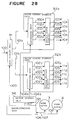
- control means 9a is constituted similar to the control means 9 in Figure 24 except provision of an output control unit 94 that is installed in addition to the administration unit 93.
- the output control unit 94 measures the signal 107 inputted by the administration unit 93 for detecting the amount of movement of the printheads 1a and 1b in the main scan direction by monitoring the rotational angle of the scan motor and outputs to the drive signal forming units 92a and 92b the instruction signals 104a and 10b instructing to which nozzles ink is to be outputted at every time where the printheads 1a and 1b are moved by 10 dots.
- a printed dot contiguous to a printed dot d 3 or d 4 in the main scan direction is printed by a nozzle that is always different from a nozzle for printing the printed dot d 3 or d 4 whereby a print result the same as that in the interlace printing is provided.
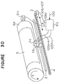
- control means 9 in Embodiment 9 of the present invention illustrated by Figure 22 may be constituted as a control means 9b as illustrated by Figure 30.
- the printheads 1a and 1b correspond to those in Figure 22 of the above-described embodiment.
- Feed rollers 21a and 21b and eject rollers 22a and 22b feed and eject the receiving medium 31.
- Print image is formed on a print roller 23 as an intermediate transfer medium by ejecting ink on a surface thereof by the printheads 1a and 1b.
- a transfer roller 24 forms final printed dots d 0 on the receiving medium 31 for transfer printed dots formed on the print roller 23 by pressing the transfer roller 24.
- a cleaning unit 25 cleans the surface by absorbing ink remaining on the print roller 23 after the transfer operation.
- the control means 9c when a first image printing operation has been finished by the printheads 1a and 1b scanning in the main scan direction in accordance with a signal for detecting the amount of movement of the printheads in the main scan direction by monitoring the rotational angle by a driving scan motor, not illustrated, the receiving medium 31 is fed between the print roller 23 rotated by an angle corresponding to a constant distance of P dots on the periphery by a driving feed motor, not illustrated, and the transfer roller 24 that is rotated by a speed and a feed amount in synchronism with the peripheral speed and the rotated angle of the print roller 23, and printing element drive signals formed based on inputted information data are outputted to the printheads 1a and 1b.
- the image printing can be carried out with certainty by a pressing force on the receiving medium 31 for transferring the printed dots after the printed dots have been formed by ejecting ink on the surface of the print roller 23 by which choice of ink for providing higher quality image can be diversified.
- k, n and m may be any values so far as the above-described conditions for arranging the printing elements are satisfied and the printheads are naturally applicable to a color system.
- ink jet heads as groups of printing elements
- other groups of printing elements capable of forming dots on a receiving medium, such as thermal heads may be used.
- a multiple element printer in which dot diameters of the 1-th one of the printing elements and the N-th one of the printing elements of the printhead are made adjustable in accordance with values of the printing element drive signals. Then, in addition to an effect achieved by alternately printing the dots at odd ordinal numbers and the dots at even ordinal numbers on substantially the same print lines by the 1-th one of the printing elements and the N-th one of the printing elements, the dot diameters of the 1-th one of the printing elements and N-th one of the printing elements are properly set. In this way, the effect of restraining occurrence of streaks due to an error in feeding the receiving medium in the sub scan direction is more promoted and printed images having high quality are obtained.
- a multiple element printer in which the values of the plurality of printing element drive signals stored in storing means by inputting means, are instructed, and dot diameter setting means sets the values of the printing element drive signals in accordance with an instruction of the inputting means. Accordingly, the set values of different dot diameters sizes can selectively set by which occurrence of streaks due to an error in feeding the receiving medium in the sub scan direction can be restrained and an adjusting operation for preventing the occurrence of streaks can simply be conducted.
- a multiple element printer in which the values of the plurality of printing element drive signals are stored in storing means and dot diameter setting means sets different values of the printing element drive signals stored in the storing means at every time of printing a predetermined number of the print lines when the receiving medium is instructed to print. Accordingly, a test printing in which dot diameter sizes are changed and a test printing of printing data by constant width can be carried out in respect of one dot diameter size. In this way an operation of adjusting image quality can more efficiently be performed and images having excellent quality can simply be obtained.
- the multiple element printer prevents occurrence of streaks even if an error is caused in feed accuracy of the receiving medium or accuracy of attaching the printhead and accordingly, adverse influence thereof can be restrained in printed images and images having stable image quality can be obtained.
- a multiple element printer in which an intermediate transfer medium is moved in the direction of feeding the receiving medium by a distance of P dots at every time of scanning a printhead, the printhead prints dots on a surface of the intermediate transfer medium in place of the surface of the receiving medium and the dots printed on the surface of the intermediate transfer medium are transferred onto the receiving medium by placing the surface of the intermediate transfer medium to the receiving medium. Accordingly, even if ink having poor absorbability in respect of the receiving medium is used, image printing in respect of receiving medium can firmly be carried out by the pressing force by which choice of ink for obtaining print images having higher image quality can be diversified.
- a multiple element printer in which N of printing elements are arranged in a printhead at intervals of k dots where k and N are positive integers mutually prime with each other, in a direction of feeding a receiving medium, first driving means is controlled by controlling means such that the receiving medium is moved by a distance of N dots at every printing and scanning of a printhead in a direction of print lines, printing element drive signals for driving the respective printing elements to the printhead based on information data by printing element drive signal forming means and sizes of dot diameters printed by a 1-th one of printing elements and an N-th one of the printing elements are adjusted by dot diameter adjusting means.
- the multiple element printer carries out interlace printing and an error is caused in feed accuracy of the receiving medium or accuracy in attaching the printhead, occurrence of streaks is prevented, adverse influence thereof can be prevented in printed images and images having stable image quality can be obtained.
- the dot diameter adjusting means adjusts the sizes of the dot diameters printed by the 1-th one of the printing elements and the N-th one of the printing elements, and adjust sizes of dot diameters printed by a 2-th one of the printing elements and a (N-1)-th one of the printing elements. Accordingly, the sizes of the dot diameters printed by the 2-th one and the (N-1)-th one of the printed elements can be changed in a direction reverse to a direction of changing the sizes of dot diameters of dots printed by the 1-th one and the N-th one of the print elements by which occurrence of streaks can more firmly be restrained and printed images having higher quality can be obtained.
- a method of adjusting a multiple element printer for printing information by scanning in a direction of printing lines a printhead arranged with N of printing elements for printing dots on a surface of a receiving medium at intervals of k dots where k and N are positive integers mutually prime with each other, in a direction of moving the receiving medium by moving the receiving medium by a distance of P dots where N P+1 at every printing and scanning of the printhead in the direction of the print lines orthogonal to the direction of moving the printhead, the method comprising a printing step of printing a predetermined number of lines by the respective printing elements such that a 1-th one and an N-th one of the printing elements alternately print the dots of odd ordinal numbers and the dots of even ordinal numbers substantially on a same print line and an adjusting step of adjusting dot sizes of the 1-th one and the N-th one of the printing elements.
- the dot diameters of the 1-th one of the printing elements and the N-th one of the print elements are properly set by which an effect of restraining occurrence of streaks due to an error in feeding the receiving medium in the sub scan direction can be promoted and printed images having high quality can be obtained.
- a method of adjusting a multiple element printer for printing information by scanning in a direction of print lines a printhead arranged with N of printing elements for printing dots on a surface of a receiving medium at intervals of k dots where k and N are positive integers mutually prime with each other, in a direction of moving the receiving medium by moving the receiving medium by a distance of P dots where N P+1 at every printing and scanning of printhead in the direction of the print lines orthogonal to the direction of feeding the printhead, the method comprising a printing step of printing a predetermined number of lines by the respective printing elements and an adjusting step of adjusting dot sizes of a 1-th one of the printing elements and an N-th one of the printing elements.
- the printhead is scanned at plural times in the main scan direction and a printhead is fed in the sub scan direction by a unit of a minimum resolution, or the conventional interlace printing system by which a disturbance of image quality of images due to a dispersion of printing elements is reduced by using printing elements for printing contiguous lines which are different from each other and a dispersion in feed accuracy of a receiving medium is made uniform in respect of a total of a print region, the present invention provides stable image quality by using printed elements for printing contiguous lines which are different from each other and making uniform the dispersion of the printing elements and a fabrication dispersion of the respective printheads.
- high-speed printing can be carried out by decreasing the amount in the sub scan direction by a factor of a number of the printheads. Also, a system of increasing the number of the printing elements by high density information of the printing elements or prolongation of the printhead which deteriorates the fabrication yield, is not adopted by which the cost is reduced. In addition to the above-described effects, the following effects are achieved by the respective aspects of the present invention.
Landscapes
- Physics & Mathematics (AREA)
- Engineering & Computer Science (AREA)
- Mathematical Physics (AREA)
- General Engineering & Computer Science (AREA)
- General Physics & Mathematics (AREA)
- Theoretical Computer Science (AREA)
- Ink Jet (AREA)
- Particle Formation And Scattering Control In Inkjet Printers (AREA)
- Electronic Switches (AREA)
Applications Claiming Priority (6)
| Application Number | Priority Date | Filing Date | Title |
|---|---|---|---|
| JP8968196 | 1996-04-11 | ||
| JP89681/96 | 1996-04-11 | ||
| JP8089681A JPH09277601A (ja) | 1996-04-11 | 1996-04-11 | 多重素子プリンタ及びこのプリンタの調整方法 |
| JP8266044A JPH10109442A (ja) | 1996-10-07 | 1996-10-07 | 多重素子プリンタ |
| JP266044/96 | 1996-10-07 | ||
| JP26604496 | 1996-10-07 |
Publications (3)
| Publication Number | Publication Date |
|---|---|
| EP0800923A2 true EP0800923A2 (de) | 1997-10-15 |
| EP0800923A3 EP0800923A3 (de) | 1998-05-06 |
| EP0800923B1 EP0800923B1 (de) | 2004-09-01 |
Family
ID=26431095
Family Applications (1)
| Application Number | Title | Priority Date | Filing Date |
|---|---|---|---|
| EP97105733A Expired - Lifetime EP0800923B1 (de) | 1996-04-11 | 1997-04-08 | Mit einer Vielzahl von Elementen arbeitender Drucker und zugehöriges Justierverfahren |
Country Status (6)
| Country | Link |
|---|---|
| US (1) | US5988790A (de) |
| EP (1) | EP0800923B1 (de) |
| KR (1) | KR100239604B1 (de) |
| CN (1) | CN1168320A (de) |
| CA (1) | CA2202002C (de) |
| DE (1) | DE69730461T2 (de) |
Cited By (5)
| Publication number | Priority date | Publication date | Assignee | Title |
|---|---|---|---|---|
| EP0878772A2 (de) * | 1997-05-14 | 1998-11-18 | Seiko Epson Corporation | Drucksystem und -verfahren |
| EP0931668A2 (de) * | 1998-01-27 | 1999-07-28 | Fuji Photo Film Co., Ltd. | Aufzeichnungsverfahren für einen Tintenstrahldrucker |
| EP0941859A1 (de) * | 1998-03-12 | 1999-09-15 | Brother Kogyo Kabushiki Kaisha | Druckgerät, Druckersystem und Speichermedium |
| EP1110740A1 (de) * | 1998-09-02 | 2001-06-27 | Star Micronics Co., Ltd. | Verfahren und gerät zum drucken auf endlosem material, verfahren und gert zum rotationsdruck und rotationsdruckkopf |
| CN1690848B (zh) * | 2004-04-27 | 2010-08-25 | 大日本网目版制造株式会社 | 图像记录装置 |
Families Citing this family (19)
| Publication number | Priority date | Publication date | Assignee | Title |
|---|---|---|---|---|
| US6439677B1 (en) * | 1997-05-20 | 2002-08-27 | Seiko Epson Corporation | Printer and printing therefor |
| JPH11208029A (ja) * | 1998-01-21 | 1999-08-03 | Seiko Epson Corp | 印刷装置および印刷方法並びに記録媒体 |
| US6590598B2 (en) * | 2000-02-28 | 2003-07-08 | Fuji Photo Film Co., Ltd. | Image forming apparatus |
| US7317553B2 (en) * | 2000-09-27 | 2008-01-08 | Seiko Epson Corporation | Settings of sub-scan feed error and sub-scan feed amount suitable for printing medium |
| US7417768B1 (en) * | 2000-10-13 | 2008-08-26 | Hewlett-Packard Development Company, L.P. | Apparatus and method for mitigating colorant-deposition errors in incremental printing |
| US6592203B1 (en) | 2002-02-11 | 2003-07-15 | Lexmark International, Inc. | Subcovered printing mode for a printhead with multiple sized ejectors |
| US6960037B2 (en) * | 2002-09-20 | 2005-11-01 | Fuji Photo Film Co., Ltd. | Printer and feeding control method |
| US6712442B1 (en) | 2002-09-23 | 2004-03-30 | Lexmark International, Inc. | Method of image rasterization and imaging an address space an ink jet printers |
| JP4200372B2 (ja) * | 2003-10-02 | 2008-12-24 | セイコーエプソン株式会社 | 被記録媒体の送り精度調整装置、記録装置、液体噴射装置及び被記録媒体の送り精度調整方法 |
| JP4412379B2 (ja) * | 2007-10-01 | 2010-02-10 | ブラザー工業株式会社 | 画像形成装置 |
| JP4412378B2 (ja) * | 2007-10-01 | 2010-02-10 | ブラザー工業株式会社 | 画像形成装置 |
| WO2009116255A1 (ja) * | 2008-03-17 | 2009-09-24 | 大日本スクリーン製造株式会社 | 画像記録装置 |
| JP5538752B2 (ja) * | 2009-06-10 | 2014-07-02 | キヤノン株式会社 | 記録装置、記録方法及び画像処理装置 |
| JP5812261B2 (ja) | 2011-06-30 | 2015-11-11 | ブラザー工業株式会社 | 印刷装置、および、コンピュータプログラム |
| JP5817257B2 (ja) | 2011-06-30 | 2015-11-18 | ブラザー工業株式会社 | 印刷装置、印刷装置に関する設定を行う設定方法 |
| JP5807412B2 (ja) | 2011-06-30 | 2015-11-10 | ブラザー工業株式会社 | 印刷装置、印刷装置に関する設定方法、コンピュータプログラム |
| EP3838597A4 (de) * | 2018-08-17 | 2022-04-27 | Mimaki Engineering Co., Ltd. | Druckvorrichtung und druckverfahren |
| JP7371418B2 (ja) * | 2019-09-30 | 2023-10-31 | セイコーエプソン株式会社 | 液体吐出装置 |
| CN114100876B (zh) * | 2021-11-12 | 2024-07-23 | 深圳市奥极因科技有限公司 | 一种通过智能算法对离心机转子偏转状态定位控制的方法 |
Citations (5)
| Publication number | Priority date | Publication date | Assignee | Title |
|---|---|---|---|---|
| JPS57176176A (en) * | 1981-04-23 | 1982-10-29 | Hitachi Ltd | Printing system |
| EP0458650A2 (de) * | 1990-05-25 | 1991-11-27 | Tektronix Inc. | Verfahren und Vorrichtung zum mehrfarbigen verketteten Drucken |
| EP0507328A2 (de) * | 1991-04-05 | 1992-10-07 | Seiko Epson Corporation | Druckverfahren für einen Seriendrucker und Seriendrucker hierfür |
| EP0517543A2 (de) * | 1991-06-07 | 1992-12-09 | Canon Kabushiki Kaisha | Farbstrahlaufzeichnungsverfahren |
| EP0679518A1 (de) * | 1994-03-02 | 1995-11-02 | Seiko Epson Corporation | Druckkopf, speziell für den Gebrauch eines seriellen Druckers |
Family Cites Families (6)
| Publication number | Priority date | Publication date | Assignee | Title |
|---|---|---|---|---|
| US4069486A (en) * | 1976-06-28 | 1978-01-17 | International Business Machines Corporation | Single array ink jet printer |
| US4198642A (en) * | 1978-01-09 | 1980-04-15 | The Mead Corporation | Ink jet printer having interlaced print scheme |
| JPS5843028B2 (ja) * | 1978-09-25 | 1983-09-24 | 株式会社リコー | 荷電偏向型マルチインクジェットプロッタ− |
| JPH0792917B2 (ja) * | 1988-07-19 | 1995-10-09 | キヤノン株式会社 | 光学的情報再生及び消去方法 |
| US5760807A (en) * | 1993-08-05 | 1998-06-02 | Seiko Epson Corporation | Ink jet recording method and ink jet recording apparatus |
| JP3329167B2 (ja) * | 1995-12-20 | 2002-09-30 | セイコーエプソン株式会社 | 印刷装置 |
-
1997
- 1997-04-04 US US08/834,551 patent/US5988790A/en not_active Expired - Fee Related
- 1997-04-07 CA CA002202002A patent/CA2202002C/en not_active Expired - Fee Related
- 1997-04-08 DE DE69730461T patent/DE69730461T2/de not_active Expired - Fee Related
- 1997-04-08 EP EP97105733A patent/EP0800923B1/de not_active Expired - Lifetime
- 1997-04-09 CN CN97113058A patent/CN1168320A/zh active Pending
- 1997-04-09 KR KR1019970012999A patent/KR100239604B1/ko not_active IP Right Cessation
Patent Citations (5)
| Publication number | Priority date | Publication date | Assignee | Title |
|---|---|---|---|---|
| JPS57176176A (en) * | 1981-04-23 | 1982-10-29 | Hitachi Ltd | Printing system |
| EP0458650A2 (de) * | 1990-05-25 | 1991-11-27 | Tektronix Inc. | Verfahren und Vorrichtung zum mehrfarbigen verketteten Drucken |
| EP0507328A2 (de) * | 1991-04-05 | 1992-10-07 | Seiko Epson Corporation | Druckverfahren für einen Seriendrucker und Seriendrucker hierfür |
| EP0517543A2 (de) * | 1991-06-07 | 1992-12-09 | Canon Kabushiki Kaisha | Farbstrahlaufzeichnungsverfahren |
| EP0679518A1 (de) * | 1994-03-02 | 1995-11-02 | Seiko Epson Corporation | Druckkopf, speziell für den Gebrauch eines seriellen Druckers |
Non-Patent Citations (1)
| Title |
|---|
| PATENT ABSTRACTS OF JAPAN vol. 007, no. 024 (M-189), 29 January 1983 & JP 57 176176 A (HITACHI SEISAKUSHO KK), 29 October 1982, * |
Cited By (10)
| Publication number | Priority date | Publication date | Assignee | Title |
|---|---|---|---|---|
| EP0878772A2 (de) * | 1997-05-14 | 1998-11-18 | Seiko Epson Corporation | Drucksystem und -verfahren |
| EP0878772A3 (de) * | 1997-05-14 | 2001-01-17 | Seiko Epson Corporation | Drucksystem und -verfahren |
| US6334665B1 (en) | 1997-05-14 | 2002-01-01 | Seiko Epson Corporation | Printing system and method of printing |
| EP0931668A2 (de) * | 1998-01-27 | 1999-07-28 | Fuji Photo Film Co., Ltd. | Aufzeichnungsverfahren für einen Tintenstrahldrucker |
| EP0931668A3 (de) * | 1998-01-27 | 2000-02-02 | Fuji Photo Film Co., Ltd. | Aufzeichnungsverfahren für einen Tintenstrahldrucker |
| EP0941859A1 (de) * | 1998-03-12 | 1999-09-15 | Brother Kogyo Kabushiki Kaisha | Druckgerät, Druckersystem und Speichermedium |
| US6603564B1 (en) | 1998-03-12 | 2003-08-05 | Brother Kogyo Kabushiki Kaisha | Printing device, printing system, and storage medium |
| EP1110740A1 (de) * | 1998-09-02 | 2001-06-27 | Star Micronics Co., Ltd. | Verfahren und gerät zum drucken auf endlosem material, verfahren und gert zum rotationsdruck und rotationsdruckkopf |
| EP1110740A4 (de) * | 1998-09-02 | 2003-04-02 | Star Mfg Co | Verfahren und gerät zum drucken auf endlosem material, verfahren und gert zum rotationsdruck und rotationsdruckkopf |
| CN1690848B (zh) * | 2004-04-27 | 2010-08-25 | 大日本网目版制造株式会社 | 图像记录装置 |
Also Published As
| Publication number | Publication date |
|---|---|
| DE69730461T2 (de) | 2005-09-01 |
| US5988790A (en) | 1999-11-23 |
| CA2202002A1 (en) | 1997-10-11 |
| DE69730461D1 (de) | 2004-10-07 |
| EP0800923B1 (de) | 2004-09-01 |
| CN1168320A (zh) | 1997-12-24 |
| KR970069338A (ko) | 1997-11-07 |
| KR100239604B1 (ko) | 2000-01-15 |
| CA2202002C (en) | 2000-05-16 |
| EP0800923A3 (de) | 1998-05-06 |
Similar Documents
| Publication | Publication Date | Title |
|---|---|---|
| US5988790A (en) | Multiple element printer and method of adjusting thereof | |
| US6457806B2 (en) | Ink-jet print pass microstepping | |
| EP0827107B1 (de) | Matrix-Druckverfahren und -gerät | |
| EP0817113A2 (de) | Tintenstrahlaufzeichnungsverfahren | |
| EP0817114B1 (de) | Punktzuweisungsplanung in Tintenstrahldruckern | |
| EP1029693A1 (de) | Mehrgängiges Drucken | |
| US7370927B2 (en) | Recording apparatus | |
| JP4598249B2 (ja) | 非一様なオーバーラップ印刷 | |
| EP0497614B1 (de) | Verfahren zum verschachtelten Hochgeschwindigkeitsdruck Gemäss der Abtastrichtung der Druckkopfachse | |
| US6069709A (en) | Bi-directional printing with overlap using both breaks and transition regions | |
| EP0738068A2 (de) | Zufallsdrucktechniquen für Drucker mit flüssiger Tinte | |
| US6174037B1 (en) | Multiple pass ink jet printer with optimized power supply | |
| EP1014299B1 (de) | Farbdruck unter Verwendung eines vertikalen Düsenreihenkopfes | |
| US7093925B2 (en) | Method and device for printing with a uniform printing medium transport distance | |
| US20060146080A1 (en) | Ink jet printing device and image forming apparatus | |
| JP2000094753A (ja) | 記録装置及び記録装置の制御方法 | |
| JPH10157087A (ja) | インクジェット記録装置 | |
| JPH11268344A (ja) | ドット記録方法およびドット記録装置、並びに、そのための記録媒体 | |
| US5779377A (en) | Printing apparatus | |
| US20030137556A1 (en) | Draft printing with multiple same-hue ink nozzles | |
| EP1676710B1 (de) | Druckvorrichtung und Verfahren zur deren Ansteuerung | |
| JPH09277601A (ja) | 多重素子プリンタ及びこのプリンタの調整方法 | |
| EP1479522B1 (de) | Verfahren und Vorrichtung zum Drucken mit einem konstanten Druckmedientransportabstand | |
| JP3592039B2 (ja) | インクジェット記録装置 | |
| JP3531892B2 (ja) | インクジェット記録装置 |
Legal Events
| Date | Code | Title | Description |
|---|---|---|---|
| PUAI | Public reference made under article 153(3) epc to a published international application that has entered the european phase |
Free format text: ORIGINAL CODE: 0009012 |
|
| AK | Designated contracting states |
Kind code of ref document: A2 Designated state(s): DE FR GB |
|
| PUAL | Search report despatched |
Free format text: ORIGINAL CODE: 0009013 |
|
| RHK1 | Main classification (correction) |
Ipc: G06K 15/10 |
|
| AK | Designated contracting states |
Kind code of ref document: A3 Designated state(s): DE FR GB |
|
| 17P | Request for examination filed |
Effective date: 19980616 |
|
| 17Q | First examination report despatched |
Effective date: 20030428 |
|
| GRAP | Despatch of communication of intention to grant a patent |
Free format text: ORIGINAL CODE: EPIDOSNIGR1 |
|
| GRAS | Grant fee paid |
Free format text: ORIGINAL CODE: EPIDOSNIGR3 |
|
| GRAA | (expected) grant |
Free format text: ORIGINAL CODE: 0009210 |
|
| AK | Designated contracting states |
Kind code of ref document: B1 Designated state(s): DE FR GB |
|
| REG | Reference to a national code |
Ref country code: GB Ref legal event code: FG4D |
|
| REF | Corresponds to: |
Ref document number: 69730461 Country of ref document: DE Date of ref document: 20041007 Kind code of ref document: P |
|
| PLBE | No opposition filed within time limit |
Free format text: ORIGINAL CODE: 0009261 |
|
| STAA | Information on the status of an ep patent application or granted ep patent |
Free format text: STATUS: NO OPPOSITION FILED WITHIN TIME LIMIT |
|
| ET | Fr: translation filed | ||
| 26N | No opposition filed |
Effective date: 20050602 |
|
| PGFP | Annual fee paid to national office [announced via postgrant information from national office to epo] |
Ref country code: GB Payment date: 20060405 Year of fee payment: 10 |
|
| PGFP | Annual fee paid to national office [announced via postgrant information from national office to epo] |
Ref country code: DE Payment date: 20060406 Year of fee payment: 10 |
|
| PGFP | Annual fee paid to national office [announced via postgrant information from national office to epo] |
Ref country code: FR Payment date: 20060410 Year of fee payment: 10 |
|
| GBPC | Gb: european patent ceased through non-payment of renewal fee |
Effective date: 20070408 |
|
| PG25 | Lapsed in a contracting state [announced via postgrant information from national office to epo] |
Ref country code: DE Free format text: LAPSE BECAUSE OF NON-PAYMENT OF DUE FEES Effective date: 20071101 |
|
| PG25 | Lapsed in a contracting state [announced via postgrant information from national office to epo] |
Ref country code: GB Free format text: LAPSE BECAUSE OF NON-PAYMENT OF DUE FEES Effective date: 20070408 |
|
| PG25 | Lapsed in a contracting state [announced via postgrant information from national office to epo] |
Ref country code: FR Free format text: LAPSE BECAUSE OF NON-PAYMENT OF DUE FEES Effective date: 20070430 |