EP0800868B1 - Dispergiersystem für eine Pulversprüheinrichtung - Google Patents
Dispergiersystem für eine Pulversprüheinrichtung Download PDFInfo
- Publication number
- EP0800868B1 EP0800868B1 EP97105590A EP97105590A EP0800868B1 EP 0800868 B1 EP0800868 B1 EP 0800868B1 EP 97105590 A EP97105590 A EP 97105590A EP 97105590 A EP97105590 A EP 97105590A EP 0800868 B1 EP0800868 B1 EP 0800868B1
- Authority
- EP
- European Patent Office
- Prior art keywords
- powder
- air
- control air
- air stream
- dispersion apparatus
- Prior art date
- Legal status (The legal status is an assumption and is not a legal conclusion. Google has not performed a legal analysis and makes no representation as to the accuracy of the status listed.)
- Expired - Lifetime
Links
Images


Classifications
-
- B—PERFORMING OPERATIONS; TRANSPORTING
- B05—SPRAYING OR ATOMISING IN GENERAL; APPLYING FLUENT MATERIALS TO SURFACES, IN GENERAL
- B05B—SPRAYING APPARATUS; ATOMISING APPARATUS; NOZZLES
- B05B5/00—Electrostatic spraying apparatus; Spraying apparatus with means for charging the spray electrically; Apparatus for spraying liquids or other fluent materials by other electric means
- B05B5/025—Discharge apparatus, e.g. electrostatic spray guns
- B05B5/03—Discharge apparatus, e.g. electrostatic spray guns characterised by the use of gas, e.g. electrostatically assisted pneumatic spraying
- B05B5/032—Discharge apparatus, e.g. electrostatic spray guns characterised by the use of gas, e.g. electrostatically assisted pneumatic spraying for spraying particulate materials
-
- B—PERFORMING OPERATIONS; TRANSPORTING
- B05—SPRAYING OR ATOMISING IN GENERAL; APPLYING FLUENT MATERIALS TO SURFACES, IN GENERAL
- B05D—PROCESSES FOR APPLYING FLUENT MATERIALS TO SURFACES, IN GENERAL
- B05D1/00—Processes for applying liquids or other fluent materials
- B05D1/02—Processes for applying liquids or other fluent materials performed by spraying
- B05D1/04—Processes for applying liquids or other fluent materials performed by spraying involving the use of an electrostatic field
-
- B—PERFORMING OPERATIONS; TRANSPORTING
- B05—SPRAYING OR ATOMISING IN GENERAL; APPLYING FLUENT MATERIALS TO SURFACES, IN GENERAL
- B05C—APPARATUS FOR APPLYING FLUENT MATERIALS TO SURFACES, IN GENERAL
- B05C19/00—Apparatus specially adapted for applying particulate materials to surfaces
- B05C19/008—Accessories or implements for use in connection with applying particulate materials to surfaces; not provided elsewhere in B05C19/00
-
- B—PERFORMING OPERATIONS; TRANSPORTING
- B05—SPRAYING OR ATOMISING IN GENERAL; APPLYING FLUENT MATERIALS TO SURFACES, IN GENERAL
- B05D—PROCESSES FOR APPLYING FLUENT MATERIALS TO SURFACES, IN GENERAL
- B05D1/00—Processes for applying liquids or other fluent materials
- B05D1/02—Processes for applying liquids or other fluent materials performed by spraying
- B05D1/12—Applying particulate materials
Definitions
- the invention relates to a method and a dispersing device for design a powder cloud that emerges when a powder / air mixture emerges from a Powder spraying device is created.
- the dispersing device is particularly suitable for spray devices in which a Powder / air mixture exits a fluidization chamber through a nozzle; it is but also applicable in other systems, such as a spray device, in the case of the dispersing device, a powder / air mixture via a hose is fed.
- EP A1 0574 305 describes a dispersing system with a rapidly rotating one Disc proposed, using speeds above 3000 rpm. Such However, systems are mechanically sensitive and have been used in powder sprayers only a limited service life.
- the object of the invention is a method and a Specify dispersing device with which, in addition to a design possibility of Spray cloud also improved charging can be achieved.
- This task is carried out in a method for forming a powder cloud according to the Preamble of claim 1 by introducing the control air at several points solved within the spray device.
- a dispersing device having specified features solved.
- a hollow body becomes flows through a powder / air mixture.
- the hollow body has in its wall Bores through which one or more streams of compressed air can be introduced tangentially.
- An alternative embodiment of a dispersing device is specified in claim 9.
- a powder / air stream flowing from a nozzle impinges the tip of a conical baffle and flows along the conical surface an outlet.
- the powder / air flow is passed through an annular gap, which through the cone jacket and a funnel-shaped guide wall spaced from it is formed.
- annular channel In the area of the inlet nozzle there is an annular channel with several holes arranged, through which in the tangential direction a controlling compressed air on the powder / air flow is conductive.
- this control air can also be drilled through holes in the funnel-shaped guide wall can be initiated.
- the powder spray cloud shape is not determined solely by the constructive design is, but still changeable during operation by changing the control air supply is. It can also be used with a flat nozzle. Powder deposits in the dispersing device are largely avoided. The one with the disperser achieved helical movement of the powder particles in the powder cloud leads the powder particles are very likely to be close to the high voltage electrodes over and thereby causes an improved electrostatic charge, which in turn leads to an improved deposition of powder on a workpiece.
- FIG. 1 shows a schematic representation of a section through a fluidization container 2, only a section of the container 2, which is closed per se, being shown.
- the container 2 In the container 2 there is fluidized powder 8, which can be removed from the fluid bed with the aid of a removal tube 25 and controlled by a closing device 13.
- the locking device 13 In the exemplary embodiment shown, the locking device 13 consists of a tube opening into the extraction tube 25, through which compressed air can be introduced, which in the closed state forces fluidized powder 8 back into the container 2.
- the fluidized powder 8 passes through a nozzle 11 as a powder / air stream 16 into a dispersing device 1 a.
- the dispersing device 1 is designed as a cavity 3, the through a tube 4, the nozzle 11 as an inlet for the fluidized powder 8 and through a Outlet 12 is formed.
- the cavity 3 can also have a different geometry, e.g. B. instead of a tube 4, a cone can also be used, the nozzle 11 is arranged at the beginning of the cone with the smaller diameter.
- a plurality of holes 5 are made in a row over the circumference of the tube are distributed; it is also possible to use several such rows with holes 5 in succession in the axial direction, d. H. in the spray direction. From the sectional view A-A, the design of the holes 5 can be seen more clearly. You are executed that a compressed air introduced through the bores 5 into the cavity 3 as Control air 6 tangentially touches the powder / air stream 16. This forms one towards the outlet 12 increasing helical movement of the powder / air flow 16 out.
- the outlet 12 can be made funnel-shaped, whereby - supported by the centrifugal force of those in rotation Powder particles - an expanding powder cloud 15 forms.
- the dispersing device 1 is double-walled, whereby an outer chamber 7 is created, into which the control air 6 via a feed line 9 is supplied and from which the control air 6 into the cavity 3 through the bores 5 can be initiated.
- the powder particles are charged with the aid of high-voltage electrodes 14 outside the outlet area 12.
- the shape of the powder cloud 15 can be influenced not only during operation by the supply of control air, but also by the choice and optimization of the geometry of the dispersing device.
- Some essential parameters are given in Fig. 2 . These parameters are the length L 2 , measured from the - possibly first - inlet point 5 for control air 6 and the start of the outlet 12, the distance L 1 between the nozzle 11 and the inlet point 5, the diameter D1 of the tube 4, the diameter D2 the funnel-shaped expansion of the outlet 12, the opening angle ⁇ 1 of the funnel-shaped expansion, the opening diameter D 3 of the nozzle 11, the diameter D 4 of the bores 5 and the number of bores 5.
- Fluidized powder 8 is introduced into the dispersing device in the axial direction via a nozzle 11.
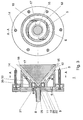
- the powder / air flow 16 generated by the nozzle 11 strikes the tip of a large conical baffle 17 just behind the nozzle 11.
- the powder / air flow 16 flows along the jacket of the conical baffle 17 to an outlet 12.
- the expanding powder / air flow 16 is guided through a guide wall 18 adapted to the cone shape.
- the guide wall 18 is part of a feed channel 19 into which control air 6 is introduced via a feed line 9, which flows out tangentially toward the powder / air stream 16 via bores 5, which are shown in the sectional drawing by a sectional plane AA.
- control air 6 also via an annular channel 20 in the axial direction, but also tangential to the Powder / air stream 16 are passed.
- the ring channel 20 is for this purpose via a second supply line 21 control air 6 is supplied, which exits through holes 22.
- the one from the Ring channel 20 through the bores 22 tangential to the powder / air stream 16 Control air 6 accelerates the powder / air flow 16 on the one hand in the axial direction and also sets it in a rotating motion.
- In the outlet area 12 are high voltage electrodes 14 arranged.
- the emerging from the slot-shaped outlet 12 Powder cloud 15 is particularly effective due to its helical movement charged.
- the shape of the powder cloud 15 can be determined by the two feed lines 9 and 21 supplied control air 6 are influenced.
- control air 6 is supplied only in such an amount as for formation the desired shape of the powder cloud 15 is required because the control air 6 Powder density reduced in an undesirable manner per se.
- the proposed dispersing device of the first and second variant or the one proposed at the same time Methods for influencing the shape of the emerging powder cloud are therefore Particularly suitable as a dispersing device for a spray device, which with a Powder / air mixture with a high powder content works, such as that in FIG. 1 indicated spraying device.
Landscapes
- Electrostatic Spraying Apparatus (AREA)
- Application Of Or Painting With Fluid Materials (AREA)
- Separation Of Particles Using Liquids (AREA)
Description
Es zeigen:
- Fig. 1
- einen Ausschnitt einer Pulversprüheinrichtung mit einer angeschlossenen ersten Variante einer Dispergiereinrichtung mit tangentialer Steuerlufteinleitung, wobei zwei Schnittebenen dargestellt sind;
- Fig. 2
- ein Gestaltungs- und Dimensionierungsbeispiel zur ersten Variante;
- Fig. 3
- eine zweite Variante einer Dispergiereinrichtung mit tangentialer Steuerlufteinleitung, wobei zwei Schnittebenen dargestellt sind.
Claims (10)
- Verfahren zur Formung der aus einer - zur elektrostatischen Pulverbeschichtung vorgesehenen - Pulversprüheinrichtung austretenden, aus einem Pulver/Luftgemisch bestehenden Pulverwolke, wobei innerhalb eines Hohlkörpers (3), den das Pulver/Luftgemisch (16) in axialer Sprührichtung durchströmt, auf den Pulver/Luftstrom (16) in tangentialer Richtung eine Druckluft als Steuerluft (6) geleitet wird, die dem Pulver/Luftstrom (16) zusätzlich zum axialen Impuls einen tangentialen Impuls verleiht, wodurch eine Aufweitung des Pulver/Luftstroms (16) zur Pulverwolke (15) unterstützt wird, dadurch gekennzeichnet, daß die Steuerluft (6) aufgeteilt in mehrere Steuerluftströme tangential an mehreren Stellen innerhalb der Sprüheinrichtung auf den Pulver/Luftstrom (16) geleitet wird.
- Dispergiereinrichtung (1) zur Formung der aus einer - zur elektrostatischen Pulverbeschichtung verwendbaren - Pulversprüheinrichtung austretenden, aus einem Pulver/Luftgemisch (8, 16) bestehenden Pulverwolke (15), wobei ein Hohlkörper (3) angeordnet ist, der einen axial in Sprührichtung angeordneten Einlaß (11) für einen Pulver/Luftstrom (16) aufweist, und einen Auslaß (12) für den durch eine Steuerluft (6) mit einem Drall versehenen Pulver/Luftstrom (16) hat, dadurch gekennzeichnet, daß der Hohlkörper (3) mehrere Bohrungen (5) in seiner Wandung (4, 18) hat, durch die Steuerluft (6) tangential auf den Pulver/Luftstrom (16) leitbar ist.
- Dispergiereinrichtung nach Anspruch 2, dadurch gekennzeichnet, daß der Hohlkörper (3) als Rohr (4) mit Bohrungen (5) für die Steuerlufteinleitung (6, 9) in seiner Wand ausgeführt ist.
- Dispergiereinrichtung nach Anspruch 2, dadurch gekennzeichnet, daß der Hohlraum (3) als Konus mit Bohrungen für die Steuerlufteinleitung ausgeführt ist, wobei sich der Einlaß für den Pulver/Luftstrom auf der Seite mit dem kleineren Durchmesser befindet.
- Dispergiereinrichtung nach einem der Ansprüche 2 bis 4, dadurch gekennzeichnet, daß die Dispergiereinrichtung doppelwandig ausgeführt ist und in einer zwischen den Wänden befindlichen äußeren Kammer (7, 19) die Steuerluft (6) einleitbar ist, die durch mehrere Bohrungen (5) in der inneren Wand (4, 18) tangential auf den Pulver/Luftstrom (16) geführt ist.
- Dispergiereinrichtung nach einem der Ansprüche 2 bis 5, dadurch gekennzeichnet, daß am Auslaß (12), beispielsweise auf das Rohr (4), eine Flachdüse aufsteckbar ist.
- Dispergiereinrichtung nach einem der Ansprüche 2 bis 6, dadurch gekennzeichnet, daß der Auslaß (12) als trichterförmige Erweiterung des Hohlkörpers (3) ausgebildet ist.
- Dispergiereinrichtung nach einem der Ansprüche 2 bis 7, dadurch gekennzeichnet, daß in relativ keinem Abstand zum Einlaß (11) für das Pulver/Luftgemisch (8, 16) in axialer Richtung, noch vor der Einleitungsstelle (5) für Steuerluft (6) ein sehr kleiner Prallkörper (10) angeordnet ist, womit eine Aufweitung des Pulver/Luftstroms (16) und eine verbesserte Wirkung der tangential eingeleiteten Steuerluft (6) erzielt wird.
- Dispergiereinrichtung (1), zur Formung der aus einer - zur elektrostatischen Pulverbeschichtung verwendbaren - Pulversprüheinrichtung austretenden, aus einem Pulver/Luftgemisch bestehenden Pulverwolke, wobei in die Einreichtung (1) in einer zur Sprührichtung vorwiegend tangentialen Richtung Steuerluft (6) einleitbar ist, die eine schraubenförmige Bewegung eines zu einem Auslaß (12) strömenden Pulver/Luftstroms (16) bewirkt, dadurch gekennzeichnet, daßa) als Einlaß eine Düse (11) angeordnet ist, durch die der Pulver/Luftstrom (16) axial in Sprührichtung in die Dispergiereinrichtung (1) eintritt,b) ein kegelförmiger Prallkörper (17) vorhanden, auf dessen Kegelspitze der Pulver/Luftstrom (16) trifft und entlang des Kegelmantels zum Auslaß (12) geleitet wird,c) eine vom Kegelmantel des Prallkörpers (17) beabstandete Wand (18) einer trichterförmigen Führung einen Ringspalt (3) bildet, durch den der Pulver/Luftstrom (16) zum Auslaß (12) geführt wird, undd) im Bereich der Düse (11) ein Ringkanal (20) mit mehreren Bohrungen (22) angeordnet ist, durch den die Steuerluft (6) einleitbar ist.
- Dispergiereinrichtung nach Anspruch 9, dadurch gekennzeichnet, daß zusätzlich zur Steuerlufteinleitung über den Ringkanal (20) oder anstelle dieser Steuerlufteinleitung eine tangentiale Einleitung von Steuerluft (6) durch Bohrungen (5) in der Führungswand (18) ermöglicht ist.
Applications Claiming Priority (2)
| Application Number | Priority Date | Filing Date | Title |
|---|---|---|---|
| DE19614192A DE19614192A1 (de) | 1996-04-10 | 1996-04-10 | Dispergiersystem für eine Pulversprüheinrichtung |
| DE19614192 | 1996-04-10 |
Publications (2)
| Publication Number | Publication Date |
|---|---|
| EP0800868A1 EP0800868A1 (de) | 1997-10-15 |
| EP0800868B1 true EP0800868B1 (de) | 1999-03-03 |
Family
ID=7790913
Family Applications (1)
| Application Number | Title | Priority Date | Filing Date |
|---|---|---|---|
| EP97105590A Expired - Lifetime EP0800868B1 (de) | 1996-04-10 | 1997-04-04 | Dispergiersystem für eine Pulversprüheinrichtung |
Country Status (6)
| Country | Link |
|---|---|
| EP (1) | EP0800868B1 (de) |
| JP (1) | JP4018192B2 (de) |
| KR (1) | KR970069152A (de) |
| DE (2) | DE19614192A1 (de) |
| DK (1) | DK0800868T3 (de) |
| ES (1) | ES2131421T3 (de) |
Families Citing this family (4)
| Publication number | Priority date | Publication date | Assignee | Title |
|---|---|---|---|---|
| ITMI20010654A1 (it) * | 2001-03-28 | 2002-09-28 | Ines Urbani | Dispositivo per verniciatura elettrostatica ad emissione lineare di polvere attraverso una doppia fenditura di qualsivoglia lunghezza per us |
| DE10138917A1 (de) | 2001-08-08 | 2003-03-06 | Itw Gema Ag | Pulversprühbeschichtungsvorrichtung |
| DE10261978B3 (de) * | 2002-01-18 | 2004-11-11 | Fraunhofer-Gesellschaft zur Förderung der angewandten Forschung e.V. | Pulversprühvorrichtung und Verfahren |
| US6874712B2 (en) * | 2002-09-27 | 2005-04-05 | Abb Inc. | Swirl gun for powder particles |
Family Cites Families (16)
| Publication number | Priority date | Publication date | Assignee | Title |
|---|---|---|---|---|
| US2879003A (en) * | 1956-09-24 | 1959-03-24 | Finn Equipment Company | Nozzles for spraying aqueous solutions containing a high percentage of solids |
| FR92033E (fr) * | 1967-03-22 | 1968-09-13 | Sames Mach Electrostat | Appareil nouveau et perfectionné pour le poudrage électrostatique d'objets |
| DE1475162A1 (de) * | 1964-11-28 | 1969-01-23 | Sem Bjarne | Spritzmundstueck |
| US3310240A (en) * | 1965-01-07 | 1967-03-21 | Gen Motors Corp | Air atomizing nozzle |
| IT992150B (it) * | 1973-05-29 | 1975-09-10 | Turbosol A I Srl | Testina spruzzatrice di impasti cementizi per l applicazione mec canica di intonaci |
| US3901184A (en) * | 1974-07-23 | 1975-08-26 | Continental Can Co | Pneumatic powder flow diverting device |
| US3940061A (en) * | 1974-09-16 | 1976-02-24 | Champion Spark Plug Company | Electrostatic spray gun for powder coating material |
| DE2923451C2 (de) * | 1979-06-09 | 1986-10-16 | Ransburg-Gema AG, St. Gallen | Verfahren und Vorrichtung zum Sprühbeschichten von Gegenständen mit Pulver |
| DE3014133C2 (de) * | 1980-04-12 | 1984-04-19 | Ransburg-Gema AG, 9015 St.Gallen | Vorrichtung zum Zerstäuben von Pulver |
| DE3242362A1 (de) * | 1982-11-16 | 1984-05-17 | Hestermann, Gerhard, 7990 Friedrichshafen | Verfahren und vorrichtung zum gerichteten auftragen pulverfoermiger anstrichstoffe |
| DE3644849A1 (de) * | 1986-03-13 | 1987-09-17 | Gema Ransburg Ag | Elektrostatische sprueheinrichtung fuer beschichtungspulver |
| GB8704749D0 (en) * | 1987-02-28 | 1987-04-01 | Hirt Combustion Eng | Atomiser |
| DE3725672A1 (de) * | 1987-08-03 | 1989-02-16 | Marresearch | Druckluftblaseinrichtung |
| FR2660215B1 (fr) * | 1990-04-02 | 1995-07-21 | Stein Industrie | Lance de dispersion de pulpe. |
| US5297733A (en) * | 1991-09-16 | 1994-03-29 | Plastic Flamecoat Systems, Inc. | Flame spray gun |
| US5322222A (en) * | 1992-10-05 | 1994-06-21 | Lott W Gerald | Spiral jet fluid mixer |
-
1996
- 1996-04-10 DE DE19614192A patent/DE19614192A1/de not_active Withdrawn
-
1997
- 1997-04-04 ES ES97105590T patent/ES2131421T3/es not_active Expired - Lifetime
- 1997-04-04 DE DE59700097T patent/DE59700097D1/de not_active Expired - Lifetime
- 1997-04-04 EP EP97105590A patent/EP0800868B1/de not_active Expired - Lifetime
- 1997-04-04 DK DK97105590T patent/DK0800868T3/da active
- 1997-04-08 JP JP08955397A patent/JP4018192B2/ja not_active Expired - Fee Related
- 1997-04-09 KR KR1019970012981A patent/KR970069152A/ko not_active Withdrawn
Also Published As
| Publication number | Publication date |
|---|---|
| JPH1034028A (ja) | 1998-02-10 |
| DK0800868T3 (da) | 1999-10-04 |
| JP4018192B2 (ja) | 2007-12-05 |
| DE59700097D1 (de) | 1999-04-08 |
| DE19614192A1 (de) | 1997-10-16 |
| KR970069152A (ko) | 1997-11-07 |
| ES2131421T3 (es) | 1999-07-16 |
| EP0800868A1 (de) | 1997-10-15 |
Similar Documents
| Publication | Publication Date | Title |
|---|---|---|
| DE69503946T2 (de) | Gas-Zerstäuber mit reduziertem Rückfluss | |
| DE69923360T2 (de) | Thermische Lichtbogenspritzpistole und ihre Gaskappe | |
| EP1986788B1 (de) | Zweistoffdüse mit kreisförmig angeordneten sekundärluftdüsen | |
| EP0076472B1 (de) | Vorrichtung zum gleichmässigen Verteilen eines Schüttgutstroms | |
| DE69629276T2 (de) | Flachstrahldüse | |
| DE69417679T2 (de) | Durch Ansaugen gespeiste Düse für Niederdruckspritzpistolen | |
| DE3116660C2 (de) | Mehrstoff-Zerstäuberdüse | |
| DE2541927C3 (de) | Zerstäuberdüse | |
| DE3851894T2 (de) | Flache spritzdüse für eine spritzpistole. | |
| DE3100002A1 (de) | Pulverspritzgeraet | |
| DE10126100A1 (de) | Verfahren und Vorrichtung zum Kaltgasspritzen | |
| DE2908723A1 (de) | Verfahren und vorrichtung zum elektrostatischen spruehen einer fluessigkeit | |
| DE1577919A1 (de) | Elektrostatisches Spritzgeraet | |
| DE3014133C2 (de) | Vorrichtung zum Zerstäuben von Pulver | |
| DE69518670T2 (de) | Verbesserung zu den flüssigkeitsabgabevorrichtungen | |
| EP0801990B1 (de) | Sprühdüse, insbesondere zum Versprühen von Wasser in Brandschutzanlagen | |
| EP0941145B1 (de) | Pulversprüheinrichtung | |
| DE69414872T2 (de) | Pulversprühbeschichtung | |
| DE3706694A1 (de) | Zweistoff-zerstaeubungsduese zur erzeugung eines vollkegelstrahls | |
| DE2141291C3 (de) | Sprühdüse zur Erzielung eines kegelstumpfförmigen Sprühnebels | |
| DE2757522C2 (de) | Rund- oder Ringstrahldüse zum Erzeugen und Abstrahlen eines Nebels oder Aerosols zur Beschichtung von Gegenständen | |
| DE2356229B2 (de) | Kegelstumpfförmige, radiale Gaskanäle aufweisende Zerstäuberdüse | |
| EP0800868A1 (de) | Dispergiersystem für eine Pulversprüheinrichtung | |
| DE3546231A1 (de) | Pulver-spruehpistole | |
| DE3117715C2 (de) | Pulverbeschichtungsvorrichtung |
Legal Events
| Date | Code | Title | Description |
|---|---|---|---|
| PUAI | Public reference made under article 153(3) epc to a published international application that has entered the european phase |
Free format text: ORIGINAL CODE: 0009012 |
|
| AK | Designated contracting states |
Kind code of ref document: A1 Designated state(s): BE CH DE DK ES FI FR GB IT LI NL PT SE |
|
| 17P | Request for examination filed |
Effective date: 19971004 |
|
| 17Q | First examination report despatched |
Effective date: 19980317 |
|
| GRAG | Despatch of communication of intention to grant |
Free format text: ORIGINAL CODE: EPIDOS AGRA |
|
| GRAG | Despatch of communication of intention to grant |
Free format text: ORIGINAL CODE: EPIDOS AGRA |
|
| GRAH | Despatch of communication of intention to grant a patent |
Free format text: ORIGINAL CODE: EPIDOS IGRA |
|
| GRAH | Despatch of communication of intention to grant a patent |
Free format text: ORIGINAL CODE: EPIDOS IGRA |
|
| GRAH | Despatch of communication of intention to grant a patent |
Free format text: ORIGINAL CODE: EPIDOS IGRA |
|
| GRAA | (expected) grant |
Free format text: ORIGINAL CODE: 0009210 |
|
| PGFP | Annual fee paid to national office [announced via postgrant information from national office to epo] |
Ref country code: DK Payment date: 19990216 Year of fee payment: 3 |
|
| PGFP | Annual fee paid to national office [announced via postgrant information from national office to epo] |
Ref country code: SE Payment date: 19990218 Year of fee payment: 3 |
|
| AK | Designated contracting states |
Kind code of ref document: B1 Designated state(s): BE CH DE DK ES FI FR GB IT LI NL PT SE |
|
| PGFP | Annual fee paid to national office [announced via postgrant information from national office to epo] |
Ref country code: BE Payment date: 19990315 Year of fee payment: 3 |
|
| REG | Reference to a national code |
Ref country code: CH Ref legal event code: EP |
|
| ITF | It: translation for a ep patent filed | ||
| GBT | Gb: translation of ep patent filed (gb section 77(6)(a)/1977) |
Effective date: 19990308 |
|
| PGFP | Annual fee paid to national office [announced via postgrant information from national office to epo] |
Ref country code: FI Payment date: 19990401 Year of fee payment: 3 |
|
| REF | Corresponds to: |
Ref document number: 59700097 Country of ref document: DE Date of ref document: 19990408 |
|
| ET | Fr: translation filed | ||
| PGFP | Annual fee paid to national office [announced via postgrant information from national office to epo] |
Ref country code: PT Payment date: 19990513 Year of fee payment: 3 |
|
| REG | Reference to a national code |
Ref country code: ES Ref legal event code: FG2A Ref document number: 2131421 Country of ref document: ES Kind code of ref document: T3 |
|
| REG | Reference to a national code |
Ref country code: PT Ref legal event code: SC4A Free format text: AVAILABILITY OF NATIONAL TRANSLATION Effective date: 19990513 |
|
| REG | Reference to a national code |
Ref country code: DK Ref legal event code: T3 |
|
| PGFP | Annual fee paid to national office [announced via postgrant information from national office to epo] |
Ref country code: ES Payment date: 19991014 Year of fee payment: 3 |
|
| PLBE | No opposition filed within time limit |
Free format text: ORIGINAL CODE: 0009261 |
|
| STAA | Information on the status of an ep patent application or granted ep patent |
Free format text: STATUS: NO OPPOSITION FILED WITHIN TIME LIMIT |
|
| 26N | No opposition filed | ||
| PG25 | Lapsed in a contracting state [announced via postgrant information from national office to epo] |
Ref country code: SE Free format text: LAPSE BECAUSE OF NON-PAYMENT OF DUE FEES Effective date: 20000405 Ref country code: ES Free format text: THE PATENT HAS BEEN ANNULLED BY A DECISION OF A NATIONAL AUTHORITY Effective date: 20000405 |
|
| PG25 | Lapsed in a contracting state [announced via postgrant information from national office to epo] |
Ref country code: FI Free format text: LAPSE BECAUSE OF NON-PAYMENT OF DUE FEES Effective date: 20000430 Ref country code: DK Free format text: LAPSE BECAUSE OF NON-PAYMENT OF DUE FEES Effective date: 20000430 Ref country code: BE Free format text: LAPSE BECAUSE OF NON-PAYMENT OF DUE FEES Effective date: 20000430 |
|
| BERE | Be: lapsed |
Owner name: ABB RESEARCH LTD Effective date: 20000430 |
|
| PG25 | Lapsed in a contracting state [announced via postgrant information from national office to epo] |
Ref country code: PT Free format text: LAPSE BECAUSE OF NON-PAYMENT OF DUE FEES Effective date: 20001031 |
|
| EUG | Se: european patent has lapsed |
Ref document number: 97105590.0 |
|
| REG | Reference to a national code |
Ref country code: DK Ref legal event code: EBP |
|
| REG | Reference to a national code |
Ref country code: PT Ref legal event code: MM4A Free format text: LAPSE DUE TO NON-PAYMENT OF FEES Effective date: 20001031 |
|
| PG25 | Lapsed in a contracting state [announced via postgrant information from national office to epo] |
Ref country code: LI Free format text: LAPSE BECAUSE OF NON-PAYMENT OF DUE FEES Effective date: 20010503 Ref country code: CH Free format text: LAPSE BECAUSE OF NON-PAYMENT OF DUE FEES Effective date: 20010503 |
|
| PG25 | Lapsed in a contracting state [announced via postgrant information from national office to epo] |
Ref country code: NL Free format text: LAPSE BECAUSE OF NON-PAYMENT OF DUE FEES Effective date: 20011101 |
|
| REG | Reference to a national code |
Ref country code: CH Ref legal event code: PL |
|
| REG | Reference to a national code |
Ref country code: GB Ref legal event code: IF02 |
|
| NLV4 | Nl: lapsed or anulled due to non-payment of the annual fee |
Effective date: 20011101 |
|
| REG | Reference to a national code |
Ref country code: ES Ref legal event code: FD2A Effective date: 20020204 |
|
| PGFP | Annual fee paid to national office [announced via postgrant information from national office to epo] |
Ref country code: FR Payment date: 20110510 Year of fee payment: 15 Ref country code: DE Payment date: 20110421 Year of fee payment: 15 |
|
| PGFP | Annual fee paid to national office [announced via postgrant information from national office to epo] |
Ref country code: GB Payment date: 20110421 Year of fee payment: 15 |
|
| PGFP | Annual fee paid to national office [announced via postgrant information from national office to epo] |
Ref country code: IT Payment date: 20110422 Year of fee payment: 15 |
|
| GBPC | Gb: european patent ceased through non-payment of renewal fee |
Effective date: 20120404 |
|
| REG | Reference to a national code |
Ref country code: FR Ref legal event code: ST Effective date: 20121228 |
|
| PG25 | Lapsed in a contracting state [announced via postgrant information from national office to epo] |
Ref country code: GB Free format text: LAPSE BECAUSE OF NON-PAYMENT OF DUE FEES Effective date: 20120404 |
|
| REG | Reference to a national code |
Ref country code: DE Ref legal event code: R119 Ref document number: 59700097 Country of ref document: DE Effective date: 20121101 |
|
| PG25 | Lapsed in a contracting state [announced via postgrant information from national office to epo] |
Ref country code: FR Free format text: LAPSE BECAUSE OF NON-PAYMENT OF DUE FEES Effective date: 20120430 Ref country code: IT Free format text: LAPSE BECAUSE OF NON-PAYMENT OF DUE FEES Effective date: 20120404 |
|
| PG25 | Lapsed in a contracting state [announced via postgrant information from national office to epo] |
Ref country code: DE Free format text: LAPSE BECAUSE OF NON-PAYMENT OF DUE FEES Effective date: 20121101 |