EP0800765A2 - Verfahren zur Vorbereitung von Organen auf Langzeitkonservierung und Transplantation - Google Patents
Verfahren zur Vorbereitung von Organen auf Langzeitkonservierung und Transplantation Download PDFInfo
- Publication number
- EP0800765A2 EP0800765A2 EP97107891A EP97107891A EP0800765A2 EP 0800765 A2 EP0800765 A2 EP 0800765A2 EP 97107891 A EP97107891 A EP 97107891A EP 97107891 A EP97107891 A EP 97107891A EP 0800765 A2 EP0800765 A2 EP 0800765A2
- Authority
- EP
- European Patent Office
- Prior art keywords
- organ
- concentration
- cryoprotectant
- fluid
- osmotic
- Prior art date
- Legal status (The legal status is an assumption and is not a legal conclusion. Google has not performed a legal analysis and makes no representation as to the accuracy of the status listed.)
- Granted
Links
- 210000000056 organ Anatomy 0.000 title claims abstract description 204
- 238000000034 method Methods 0.000 title claims abstract description 68
- 238000002054 transplantation Methods 0.000 title claims abstract description 19
- 238000004321 preservation Methods 0.000 title claims abstract description 9
- 230000007774 longterm Effects 0.000 title claims abstract description 6
- 239000002577 cryoprotective agent Substances 0.000 claims abstract description 128
- 230000003204 osmotic effect Effects 0.000 claims abstract description 52
- 238000004017 vitrification Methods 0.000 claims abstract description 22
- 230000002829 reductive effect Effects 0.000 claims abstract description 13
- 239000006172 buffering agent Substances 0.000 claims abstract description 11
- 230000001965 increasing effect Effects 0.000 claims abstract description 5
- 238000005406 washing Methods 0.000 claims abstract description 3
- 230000003028 elevating effect Effects 0.000 claims abstract 4
- 230000003247 decreasing effect Effects 0.000 claims abstract 2
- 210000003734 kidney Anatomy 0.000 claims description 34
- IAZDPXIOMUYVGZ-UHFFFAOYSA-N Dimethylsulphoxide Chemical compound CS(C)=O IAZDPXIOMUYVGZ-UHFFFAOYSA-N 0.000 claims description 10
- ZHNUHDYFZUAESO-UHFFFAOYSA-N Formamide Chemical compound NC=O ZHNUHDYFZUAESO-UHFFFAOYSA-N 0.000 claims description 10
- DNIAPMSPPWPWGF-UHFFFAOYSA-N monopropylene glycol Natural products CC(O)CO DNIAPMSPPWPWGF-UHFFFAOYSA-N 0.000 claims description 7
- 238000001727 in vivo Methods 0.000 claims description 5
- 235000013772 propylene glycol Nutrition 0.000 claims description 5
- DNIAPMSPPWPWGF-GSVOUGTGSA-N (R)-(-)-Propylene glycol Chemical compound C[C@@H](O)CO DNIAPMSPPWPWGF-GSVOUGTGSA-N 0.000 claims description 4
- OWBTYPJTUOEWEK-UHFFFAOYSA-N butane-2,3-diol Chemical compound CC(O)C(C)O OWBTYPJTUOEWEK-UHFFFAOYSA-N 0.000 claims description 4
- 239000003146 anticoagulant agent Substances 0.000 claims description 2
- 229940127219 anticoagulant drug Drugs 0.000 claims description 2
- ZMXDDKWLCZADIW-UHFFFAOYSA-N Vilsmeier-Haack reagent Natural products CN(C)C=O ZMXDDKWLCZADIW-UHFFFAOYSA-N 0.000 claims 2
- 229940121363 anti-inflammatory agent Drugs 0.000 claims 1
- 239000002260 anti-inflammatory agent Substances 0.000 claims 1
- 229940127218 antiplatelet drug Drugs 0.000 claims 1
- 239000012530 fluid Substances 0.000 description 150
- 230000010412 perfusion Effects 0.000 description 90
- 239000000243 solution Substances 0.000 description 58
- 230000008569 process Effects 0.000 description 34
- 238000002156 mixing Methods 0.000 description 31
- 238000004140 cleaning Methods 0.000 description 25
- PEDCQBHIVMGVHV-UHFFFAOYSA-N Glycerine Chemical compound OCC(O)CO PEDCQBHIVMGVHV-UHFFFAOYSA-N 0.000 description 24
- XLYOFNOQVPJJNP-UHFFFAOYSA-N water Substances O XLYOFNOQVPJJNP-UHFFFAOYSA-N 0.000 description 21
- 238000001816 cooling Methods 0.000 description 19
- 230000006378 damage Effects 0.000 description 18
- 239000002699 waste material Substances 0.000 description 18
- 108091006146 Channels Proteins 0.000 description 17
- 229960002240 iloprost Drugs 0.000 description 17
- HIFJCPQKFCZDDL-ACWOEMLNSA-N iloprost Chemical compound C1\C(=C/CCCC(O)=O)C[C@@H]2[C@@H](/C=C/[C@@H](O)C(C)CC#CC)[C@H](O)C[C@@H]21 HIFJCPQKFCZDDL-ACWOEMLNSA-N 0.000 description 17
- 239000000872 buffer Substances 0.000 description 16
- 241000283973 Oryctolagus cuniculus Species 0.000 description 12
- 239000007788 liquid Substances 0.000 description 12
- 230000037452 priming Effects 0.000 description 12
- 238000010926 purge Methods 0.000 description 12
- 230000008859 change Effects 0.000 description 11
- 239000000645 desinfectant Substances 0.000 description 11
- 230000006870 function Effects 0.000 description 11
- 239000000523 sample Substances 0.000 description 11
- 230000001276 controlling effect Effects 0.000 description 10
- 238000003756 stirring Methods 0.000 description 10
- 231100000419 toxicity Toxicity 0.000 description 10
- 230000001988 toxicity Effects 0.000 description 10
- 239000003085 diluting agent Substances 0.000 description 9
- 230000009467 reduction Effects 0.000 description 9
- 239000003795 chemical substances by application Substances 0.000 description 8
- 238000007710 freezing Methods 0.000 description 8
- 230000008014 freezing Effects 0.000 description 8
- 238000001802 infusion Methods 0.000 description 8
- 230000002792 vascular Effects 0.000 description 8
- 238000005138 cryopreservation Methods 0.000 description 7
- 230000000694 effects Effects 0.000 description 7
- 210000002216 heart Anatomy 0.000 description 7
- 239000000203 mixture Substances 0.000 description 7
- 230000000149 penetrating effect Effects 0.000 description 7
- 230000004913 activation Effects 0.000 description 6
- 238000001994 activation Methods 0.000 description 6
- 238000013459 approach Methods 0.000 description 6
- 230000003750 conditioning effect Effects 0.000 description 6
- 238000002474 experimental method Methods 0.000 description 6
- 238000005259 measurement Methods 0.000 description 6
- 230000004048 modification Effects 0.000 description 6
- 238000012986 modification Methods 0.000 description 6
- 230000001954 sterilising effect Effects 0.000 description 6
- 210000001519 tissue Anatomy 0.000 description 6
- 239000012141 concentrate Substances 0.000 description 5
- 210000004185 liver Anatomy 0.000 description 5
- 229920003023 plastic Polymers 0.000 description 5
- 238000004659 sterilization and disinfection Methods 0.000 description 5
- FBPFZTCFMRRESA-KVTDHHQDSA-N D-Mannitol Chemical compound OC[C@@H](O)[C@@H](O)[C@H](O)[C@H](O)CO FBPFZTCFMRRESA-KVTDHHQDSA-N 0.000 description 4
- 229930195725 Mannitol Natural products 0.000 description 4
- 208000027418 Wounds and injury Diseases 0.000 description 4
- 210000004369 blood Anatomy 0.000 description 4
- 239000008280 blood Substances 0.000 description 4
- 239000002826 coolant Substances 0.000 description 4
- 229940079593 drug Drugs 0.000 description 4
- 239000003814 drug Substances 0.000 description 4
- 238000011067 equilibration Methods 0.000 description 4
- 230000005484 gravity Effects 0.000 description 4
- 208000014674 injury Diseases 0.000 description 4
- 239000000594 mannitol Substances 0.000 description 4
- 235000010355 mannitol Nutrition 0.000 description 4
- 230000037361 pathway Effects 0.000 description 4
- 239000004033 plastic Substances 0.000 description 4
- 238000005086 pumping Methods 0.000 description 4
- 230000003134 recirculating effect Effects 0.000 description 4
- 229920000260 silastic Polymers 0.000 description 4
- 230000004083 survival effect Effects 0.000 description 4
- IJGRMHOSHXDMSA-UHFFFAOYSA-N Atomic nitrogen Chemical compound N#N IJGRMHOSHXDMSA-UHFFFAOYSA-N 0.000 description 3
- 229930006000 Sucrose Natural products 0.000 description 3
- CZMRCDWAGMRECN-UGDNZRGBSA-N Sucrose Chemical compound O[C@H]1[C@H](O)[C@@H](CO)O[C@@]1(CO)O[C@@H]1[C@H](O)[C@@H](O)[C@H](O)[C@@H](CO)O1 CZMRCDWAGMRECN-UGDNZRGBSA-N 0.000 description 3
- 108700042768 University of Wisconsin-lactobionate solution Proteins 0.000 description 3
- 230000009286 beneficial effect Effects 0.000 description 3
- 230000008901 benefit Effects 0.000 description 3
- 230000005587 bubbling Effects 0.000 description 3
- 230000004087 circulation Effects 0.000 description 3
- 238000011109 contamination Methods 0.000 description 3
- 239000012809 cooling fluid Substances 0.000 description 3
- 230000002631 hypothermal effect Effects 0.000 description 3
- 239000000463 material Substances 0.000 description 3
- 238000012544 monitoring process Methods 0.000 description 3
- 230000008723 osmotic stress Effects 0.000 description 3
- 230000001105 regulatory effect Effects 0.000 description 3
- 230000004044 response Effects 0.000 description 3
- 239000005720 sucrose Substances 0.000 description 3
- 238000012546 transfer Methods 0.000 description 3
- 230000035899 viability Effects 0.000 description 3
- 238000010792 warming Methods 0.000 description 3
- BSYNRYMUTXBXSQ-UHFFFAOYSA-N Aspirin Chemical compound CC(=O)OC1=CC=CC=C1C(O)=O BSYNRYMUTXBXSQ-UHFFFAOYSA-N 0.000 description 2
- CURLTUGMZLYLDI-UHFFFAOYSA-N Carbon dioxide Chemical compound O=C=O CURLTUGMZLYLDI-UHFFFAOYSA-N 0.000 description 2
- HTTJABKRGRZYRN-UHFFFAOYSA-N Heparin Chemical compound OC1C(NC(=O)C)C(O)OC(COS(O)(=O)=O)C1OC1C(OS(O)(=O)=O)C(O)C(OC2C(C(OS(O)(=O)=O)C(OC3C(C(O)C(O)C(O3)C(O)=O)OS(O)(=O)=O)C(CO)O2)NS(O)(=O)=O)C(C(O)=O)O1 HTTJABKRGRZYRN-UHFFFAOYSA-N 0.000 description 2
- 208000001953 Hypotension Diseases 0.000 description 2
- 229920006328 Styrofoam Polymers 0.000 description 2
- 238000009825 accumulation Methods 0.000 description 2
- 230000009471 action Effects 0.000 description 2
- 210000001367 artery Anatomy 0.000 description 2
- 230000001413 cellular effect Effects 0.000 description 2
- 239000000084 colloidal system Substances 0.000 description 2
- 238000009833 condensation Methods 0.000 description 2
- 230000005494 condensation Effects 0.000 description 2
- 238000010276 construction Methods 0.000 description 2
- DDRJAANPRJIHGJ-UHFFFAOYSA-N creatinine Chemical compound CN1CC(=O)NC1=N DDRJAANPRJIHGJ-UHFFFAOYSA-N 0.000 description 2
- 238000013461 design Methods 0.000 description 2
- 238000000502 dialysis Methods 0.000 description 2
- 238000010790 dilution Methods 0.000 description 2
- 239000012895 dilution Substances 0.000 description 2
- 238000009826 distribution Methods 0.000 description 2
- 238000011010 flushing procedure Methods 0.000 description 2
- 238000010438 heat treatment Methods 0.000 description 2
- 229960002897 heparin Drugs 0.000 description 2
- 229920000669 heparin Polymers 0.000 description 2
- 230000036543 hypotension Effects 0.000 description 2
- 230000003834 intracellular effect Effects 0.000 description 2
- 238000001990 intravenous administration Methods 0.000 description 2
- NRXQIUSYPAHGNM-UHFFFAOYSA-N ioxynil Chemical compound OC1=C(I)C=C(C#N)C=C1I NRXQIUSYPAHGNM-UHFFFAOYSA-N 0.000 description 2
- 239000000082 organ preservation Substances 0.000 description 2
- 239000002357 osmotic agent Substances 0.000 description 2
- XQYZDYMELSJDRZ-UHFFFAOYSA-N papaverine Chemical compound C1=C(OC)C(OC)=CC=C1CC1=NC=CC2=CC(OC)=C(OC)C=C12 XQYZDYMELSJDRZ-UHFFFAOYSA-N 0.000 description 2
- 244000052769 pathogen Species 0.000 description 2
- XOJVVFBFDXDTEG-UHFFFAOYSA-N pristane Chemical compound CC(C)CCCC(C)CCCC(C)CCCC(C)C XOJVVFBFDXDTEG-UHFFFAOYSA-N 0.000 description 2
- 230000010349 pulsation Effects 0.000 description 2
- 230000000284 resting effect Effects 0.000 description 2
- 230000000717 retained effect Effects 0.000 description 2
- 230000000250 revascularization Effects 0.000 description 2
- 230000002441 reversible effect Effects 0.000 description 2
- 230000000630 rising effect Effects 0.000 description 2
- 210000002966 serum Anatomy 0.000 description 2
- 230000035939 shock Effects 0.000 description 2
- 241000894007 species Species 0.000 description 2
- 239000008261 styrofoam Substances 0.000 description 2
- 239000000126 substance Substances 0.000 description 2
- 230000009885 systemic effect Effects 0.000 description 2
- 239000002918 waste heat Substances 0.000 description 2
- RJFAYQIBOAGBLC-UHFFFAOYSA-N 2-amino-4-methylselanyl-butanoic acid Chemical compound C[Se]CCC(N)C(O)=O RJFAYQIBOAGBLC-UHFFFAOYSA-N 0.000 description 1
- 229930008281 A03AD01 - Papaverine Natural products 0.000 description 1
- 102000009027 Albumins Human genes 0.000 description 1
- 108010088751 Albumins Proteins 0.000 description 1
- 229940127291 Calcium channel antagonist Drugs 0.000 description 1
- LYCAIKOWRPUZTN-UHFFFAOYSA-N Ethylene glycol Chemical compound OCCO LYCAIKOWRPUZTN-UHFFFAOYSA-N 0.000 description 1
- WQZGKKKJIJFFOK-GASJEMHNSA-N Glucose Natural products OC[C@H]1OC(O)[C@H](O)[C@@H](O)[C@@H]1O WQZGKKKJIJFFOK-GASJEMHNSA-N 0.000 description 1
- 206010021143 Hypoxia Diseases 0.000 description 1
- VVQNEPGJFQJSBK-UHFFFAOYSA-N Methyl methacrylate Chemical compound COC(=O)C(C)=C VVQNEPGJFQJSBK-UHFFFAOYSA-N 0.000 description 1
- 229920005372 Plexiglas® Polymers 0.000 description 1
- MUPFEKGTMRGPLJ-RMMQSMQOSA-N Raffinose Natural products O(C[C@H]1[C@@H](O)[C@H](O)[C@@H](O)[C@@H](O[C@@]2(CO)[C@H](O)[C@@H](O)[C@@H](CO)O2)O1)[C@@H]1[C@H](O)[C@@H](O)[C@@H](O)[C@@H](CO)O1 MUPFEKGTMRGPLJ-RMMQSMQOSA-N 0.000 description 1
- 206010063837 Reperfusion injury Diseases 0.000 description 1
- MUPFEKGTMRGPLJ-UHFFFAOYSA-N UNPD196149 Natural products OC1C(O)C(CO)OC1(CO)OC1C(O)C(O)C(O)C(COC2C(C(O)C(O)C(CO)O2)O)O1 MUPFEKGTMRGPLJ-UHFFFAOYSA-N 0.000 description 1
- 229940068372 acetyl salicylate Drugs 0.000 description 1
- 229960001138 acetylsalicylic acid Drugs 0.000 description 1
- NIXOWILDQLNWCW-UHFFFAOYSA-N acrylic acid group Chemical group C(C=C)(=O)O NIXOWILDQLNWCW-UHFFFAOYSA-N 0.000 description 1
- 230000009056 active transport Effects 0.000 description 1
- 239000003570 air Substances 0.000 description 1
- 230000004075 alteration Effects 0.000 description 1
- 230000004872 arterial blood pressure Effects 0.000 description 1
- 239000012298 atmosphere Substances 0.000 description 1
- 230000000903 blocking effect Effects 0.000 description 1
- 230000003139 buffering effect Effects 0.000 description 1
- 239000000480 calcium channel blocker Substances 0.000 description 1
- 229910052799 carbon Inorganic materials 0.000 description 1
- 229910002092 carbon dioxide Inorganic materials 0.000 description 1
- 239000001569 carbon dioxide Substances 0.000 description 1
- 239000000969 carrier Substances 0.000 description 1
- 210000004027 cell Anatomy 0.000 description 1
- 230000004700 cellular uptake Effects 0.000 description 1
- 244000145845 chattering Species 0.000 description 1
- 239000013043 chemical agent Substances 0.000 description 1
- 231100000045 chemical toxicity Toxicity 0.000 description 1
- 230000000295 complement effect Effects 0.000 description 1
- 238000004590 computer program Methods 0.000 description 1
- 239000000470 constituent Substances 0.000 description 1
- 230000001054 cortical effect Effects 0.000 description 1
- 229940109239 creatinine Drugs 0.000 description 1
- 238000012864 cross contamination Methods 0.000 description 1
- 238000002425 crystallisation Methods 0.000 description 1
- 230000008025 crystallization Effects 0.000 description 1
- 230000001120 cytoprotective effect Effects 0.000 description 1
- 238000013016 damping Methods 0.000 description 1
- 230000007812 deficiency Effects 0.000 description 1
- 230000001934 delay Effects 0.000 description 1
- 230000003111 delayed effect Effects 0.000 description 1
- 230000002939 deleterious effect Effects 0.000 description 1
- 239000002274 desiccant Substances 0.000 description 1
- 230000001627 detrimental effect Effects 0.000 description 1
- 238000004031 devitrification Methods 0.000 description 1
- 239000008121 dextrose Substances 0.000 description 1
- 238000010586 diagram Methods 0.000 description 1
- 238000009792 diffusion process Methods 0.000 description 1
- 229910001873 dinitrogen Inorganic materials 0.000 description 1
- 239000012153 distilled water Substances 0.000 description 1
- HTAFVGKAHGNWQO-UHFFFAOYSA-N droprenilamine Chemical compound C=1C=CC=CC=1C(C=1C=CC=CC=1)CCNC(C)CC1CCCCC1 HTAFVGKAHGNWQO-UHFFFAOYSA-N 0.000 description 1
- 210000003989 endothelium vascular Anatomy 0.000 description 1
- 238000011049 filling Methods 0.000 description 1
- 239000000834 fixative Substances 0.000 description 1
- 239000011521 glass Substances 0.000 description 1
- 231100000171 higher toxicity Toxicity 0.000 description 1
- 230000002706 hydrostatic effect Effects 0.000 description 1
- 230000007954 hypoxia Effects 0.000 description 1
- 210000000987 immune system Anatomy 0.000 description 1
- 238000011065 in-situ storage Methods 0.000 description 1
- 230000006698 induction Effects 0.000 description 1
- 230000001939 inductive effect Effects 0.000 description 1
- 230000028709 inflammatory response Effects 0.000 description 1
- 230000004941 influx Effects 0.000 description 1
- 239000004615 ingredient Substances 0.000 description 1
- 230000000977 initiatory effect Effects 0.000 description 1
- 238000002347 injection Methods 0.000 description 1
- 239000007924 injection Substances 0.000 description 1
- 238000009434 installation Methods 0.000 description 1
- 238000001361 intraarterial administration Methods 0.000 description 1
- 208000028867 ischemia Diseases 0.000 description 1
- 238000005304 joining Methods 0.000 description 1
- 230000002147 killing effect Effects 0.000 description 1
- 238000002372 labelling Methods 0.000 description 1
- 230000000670 limiting effect Effects 0.000 description 1
- 238000012423 maintenance Methods 0.000 description 1
- 230000001404 mediated effect Effects 0.000 description 1
- 239000002184 metal Substances 0.000 description 1
- 229910052751 metal Inorganic materials 0.000 description 1
- 230000000813 microbial effect Effects 0.000 description 1
- 238000013059 nephrectomy Methods 0.000 description 1
- 229910052757 nitrogen Inorganic materials 0.000 description 1
- 230000037000 normothermia Effects 0.000 description 1
- 229960001789 papaverine Drugs 0.000 description 1
- 230000001991 pathophysiological effect Effects 0.000 description 1
- 230000035699 permeability Effects 0.000 description 1
- 230000002688 persistence Effects 0.000 description 1
- 230000002085 persistent effect Effects 0.000 description 1
- 230000000144 pharmacologic effect Effects 0.000 description 1
- 229920001296 polysiloxane Polymers 0.000 description 1
- 239000011148 porous material Substances 0.000 description 1
- 210000003240 portal vein Anatomy 0.000 description 1
- 230000002980 postoperative effect Effects 0.000 description 1
- 238000011045 prefiltration Methods 0.000 description 1
- 230000002028 premature Effects 0.000 description 1
- 239000003761 preservation solution Substances 0.000 description 1
- 238000002203 pretreatment Methods 0.000 description 1
- 238000007639 printing Methods 0.000 description 1
- 238000004886 process control Methods 0.000 description 1
- 238000012545 processing Methods 0.000 description 1
- 150000003174 prostaglandin I2 derivatives Chemical class 0.000 description 1
- 108090000623 proteins and genes Proteins 0.000 description 1
- 102000004169 proteins and genes Human genes 0.000 description 1
- 230000000541 pulsatile effect Effects 0.000 description 1
- 238000003908 quality control method Methods 0.000 description 1
- MUPFEKGTMRGPLJ-ZQSKZDJDSA-N raffinose Chemical compound O[C@H]1[C@H](O)[C@@H](CO)O[C@@]1(CO)O[C@@H]1[C@H](O)[C@@H](O)[C@H](O)[C@@H](CO[C@@H]2[C@@H]([C@@H](O)[C@@H](O)[C@@H](CO)O2)O)O1 MUPFEKGTMRGPLJ-ZQSKZDJDSA-N 0.000 description 1
- 210000005084 renal tissue Anatomy 0.000 description 1
- 238000009877 rendering Methods 0.000 description 1
- 238000011160 research Methods 0.000 description 1
- 230000035945 sensitivity Effects 0.000 description 1
- 238000010583 slow cooling Methods 0.000 description 1
- 238000007711 solidification Methods 0.000 description 1
- 230000008023 solidification Effects 0.000 description 1
- 239000002904 solvent Substances 0.000 description 1
- 238000009987 spinning Methods 0.000 description 1
- 230000000087 stabilizing effect Effects 0.000 description 1
- 238000003860 storage Methods 0.000 description 1
- 238000001356 surgical procedure Methods 0.000 description 1
- 230000008961 swelling Effects 0.000 description 1
- 230000001839 systemic circulation Effects 0.000 description 1
- 230000036962 time dependent Effects 0.000 description 1
- 231100000331 toxic Toxicity 0.000 description 1
- 230000002588 toxic effect Effects 0.000 description 1
- 230000001052 transient effect Effects 0.000 description 1
- 239000012780 transparent material Substances 0.000 description 1
- 238000011144 upstream manufacturing Methods 0.000 description 1
- 229940124549 vasodilator Drugs 0.000 description 1
- 239000003071 vasodilator agent Substances 0.000 description 1
- 230000000007 visual effect Effects 0.000 description 1
- 239000003643 water by type Substances 0.000 description 1
Images


Classifications
-
- A—HUMAN NECESSITIES
- A01—AGRICULTURE; FORESTRY; ANIMAL HUSBANDRY; HUNTING; TRAPPING; FISHING
- A01N—PRESERVATION OF BODIES OF HUMANS OR ANIMALS OR PLANTS OR PARTS THEREOF; BIOCIDES, e.g. AS DISINFECTANTS, AS PESTICIDES OR AS HERBICIDES; PEST REPELLANTS OR ATTRACTANTS; PLANT GROWTH REGULATORS
- A01N1/00—Preservation of bodies of humans or animals, or parts thereof
- A01N1/10—Preservation of living parts
- A01N1/14—Mechanical aspects of preservation; Apparatus or containers therefor
- A01N1/142—Apparatus
- A01N1/143—Apparatus for organ perfusion
-
- A—HUMAN NECESSITIES
- A01—AGRICULTURE; FORESTRY; ANIMAL HUSBANDRY; HUNTING; TRAPPING; FISHING
- A01N—PRESERVATION OF BODIES OF HUMANS OR ANIMALS OR PLANTS OR PARTS THEREOF; BIOCIDES, e.g. AS DISINFECTANTS, AS PESTICIDES OR AS HERBICIDES; PEST REPELLANTS OR ATTRACTANTS; PLANT GROWTH REGULATORS
- A01N1/00—Preservation of bodies of humans or animals, or parts thereof
- A01N1/10—Preservation of living parts
- A01N1/12—Chemical aspects of preservation
- A01N1/122—Preservation or perfusion media
- A01N1/125—Freeze protecting agents, e.g. cryoprotectants or osmolarity regulators
Definitions
- This invention relates to the field of organ perfusion. More particularly, it relates to a method for introducing and removing vitrifiable concentrations of cryoprotective agents into and from isolated organs or tissues for preservation and subsequent transplantation with the aid of a computer controlled apparatus.
- cryopreservation that is, preservation at very low temperatures
- the main difficulty with cryopreservation is that it requires the perfusion of organs with high concentrations of cryoprotective agents (water soluble organic molecules that minimize or prevent freezing injury during cooling to very low temperatures). No fully suitable equipment or process has been developed to date for carrying out this perfusion process. This has prevented the establishment of viable organ banks that could potentially save lives.
- the second system created changes in concentration by metering flow from a diluent reservoir and from a cryoprotectant concentrate reservoir into a mixing chamber and then to the kidney. No separate pump for controlling flow to the kidney was included. Total flow was controlled by the output of the metering pumps used for mixing. A heat exchanger was used before rather than after the filter, and there was an absence of any arterial sensing. As will become readily apparent below, the only similarity between this system and the present invention was the use of two concentration sensors, one in the arterial line and one in the venous line of the kidney. Organ flow rate was forced to vary in order to minimize A-V concentration differences.
- the sensing of concentration before and after the kidney in the circuit is analogous to but substantially inferior to the use of a refractometer and a differential refractometer in the present invention.
- the present inventors' experience has shown that the use of a differential refractometer is necessary for its greater sensitivity.
- the concept of controlling organ A-V gradient by controlling organ flow is distinctly inferior to the system of the present invention.
- the third system described by Sherwood et al . also lacked a kidney perfusion pump, relying on a "backpressure control valve" to recirculate perfusate from the filter in such a way as to maintain the desired perfusion pressure to the kidney.
- the heat exchanger is proximal to the filter and no bubble trap is present.
- the perfusate reservoir's concentration is controlled by metered addition of cryoprotectant or diluent as in the second Sherwood system, and if flow from the organ is not recirculated, major problems arise in maintaining and controlling perfusate volume and concentration. None of these features is desirable.
- the fourth system was noted by Pegg in an appendix to the main paper.
- perfusate is drained by gravity directly from the mixing reservoir to the kidney through a heat exchanger, re-entering the reservoir after passing through the kidney. Concentration is sensed also by directly and separately pumping liquid from the reservoir to the refractometer and back.
- All components of the circuit other than the kidney and a pre-kidney heat exchanger were located on a lab bench at ambient temperature, with the reservoir being thermostatted at a constant 30°C.
- the kidney and the heat exchanger were located in a styrofoam box whose internal temperature was not controlled. Despite this lack of control of the air temperature surrounding the kidney, only the arterial temperature but not the venous temperature or even the kidney surface temperature was measured. The use of a styrofoam box also did not allow for perfusion under sterile conditions.
- the only possible way of measuring organ flow rate was by switching off the effluent recirculation pump and manually recording the time required for a given volume of fluid to accumulate in the effluent reservoir, since there was no perfusion pump which specifically supplied the organ, unlike the present invention.
- Pressure was controlled, not on the basis of kidney resistance, but on the basis of the combined resistance of the kidney and a manually adjustable bypass valve used to allow rapid circulation of perfusate through the heat exchanger and back to the mixing reservoir.
- the pressure sensor was located at the arterial cannula, creating a fluid dead space requiring manual cleaning and potentially introducing undesired addition of unmixed dead space fluid into the arterial cannula.
- Pressure control was achieved by means of a specially-fabricated pressure control unit whose electrical circuit was described in an earlier paper (D.E. Pegg and C.J. Green, Renal Preservation by Hypothermic Perfusion. 1. The importance of pressure-control, Cryobiology 10 :56-66, 1973). Arterial concentration but not venous concentration was measured. No computer control or monitoring was used. Concentration was controlled by feeding the output of the recording refractometer into a "process controller" for comparison to the output of a linear voltage ramp generator and appropriate adjustment of concentrate or diluent flow rate. Glycerol concentrations were measured manually at 5 minute intervals at both the mixing reservoir and the arterial sample port: evidently, the refractometer was not used to send a measurable signal to a recording device. Temperature and flow were recorded manually at 5 minute intervals. Arterial pressure and kidney weight were recorded as pen traces on a strip chart recorder. None of these features is desirable.
- terminal cryoprotectant concentration could not be brought to less than 70 mM after adding 5 liters of diluent to the mixing reservoir (v. near-zero terminal concentrations in the present invention using less than 3 liters of diluent and using peak cryoprotectant concentrations approximately twice those of Jacobsen et al.).
- Jacobsen Jacobsen, I.A., Distribution and Removal of Glycerol by Vascular Albumin Perfusion in Rabbit Kidneys, Cryobiology 15 :302-311, 1978. Jacobsen measured but did not report air temperatures surrounding the kidney during perfusion. He reduced the mixing reservoir volume to 70 ml, which was a small fraction of the 400 ml total volume of the circuit. No electronic-output refractometer appears to have been used to directly sense glycerol concentration and control addition and washout. Instead, the calculated values of concentrate or diluent flow rate were drawn on paper with India ink and read by a Leeds and Northrup Trendtrak Programmer which then controlled the concentrate/diluent pump. Despite the low circuit volume, the minimum concentration of cryoprotectant which could be achieved was about 100 mM.
- circuits described above represent the current state of the art of cryoprotectant perfusion by others known to the present inventors.
- Vitrification or solidification without freezing, can be brought about in living systems by replacing large fractions of water in these systems with cryoprotectant agents (also known as cryoprotectants ) whose presence inhibits crystallization.
- cryoprotectant agents also known as cryoprotectants
- Vitrification typically requires concentrations greater than 6 molar cryoprotectant, whereas the limiting concentration for organ survival is typically about 4 molar.
- cryoprotectants One type of damage potentially caused by cryoprotectants is osmotic damage.
- Cryobiologists learned of the osmotic effects of cryoprotectants in the 1950's and of the necessity of controlling these effects so as to prevent unnecessary damage during the addition and removal of cryoprotectants to isolated cells and tissues. Similar lessons were learned when cryobiologists moved on to studies of whole organ perfusion with cryoprotectants. Attention to the principles of osmosis were essential to inducing tolerance to cryoprotectant addition to organs. Yet despite efforts to control deleterious osmotic effects of cryoprotectants, limits of tolerance to cryoprotectants are still observed. There appear to be genuine, inherent toxic effects of cryoprotectants that are independent of the transient osmotic effects of these chemical agents.
- the present invention overcomes substantially all of the deficiencies of known apparatus and methods.
- the present invention is directed to a computer-controlled apparatus and method for perfusing a biological organ, such as a heart, kidney, liver, etc.
- the apparatus of the invention comprises a plurality of fluid reservoirs and an organ container for holding the biological organ.
- a first fluid flow path is defined as a loop from the plurality of reservoirs to necessary sensors and temperature conditioning means and back to the plurality of reservoirs.
- the reservoirs are selectively connectable to the first fluid flow path.
- Pump means are interposed in the first fluid flow path for pumping fluid from the first fluid flow path to a second fluid flow path.
- the organ container is located in this second fluid flow path. Pump means may also be included in the second fluid flow path for pumping fluid from the organ container to one or more of the reservoirs or to waste.
- One or more sensors are interposed in the fluid flow paths for sensing at least one of the concentration, temperature, pH, and pressure of the fluid flowing in the first and second fluid flow paths.
- Measuring means are interposed in the first and second fluid flow paths for measuring concentration and temperature differences between the upstream and downstream sides, in the fluid flow direction, of the organ container.
- the sensor(s) and the measuring means are connected to a programmable computer for providing a continuous information stream from the sensor(s) to the computer.
- the computer is coupled to the selection means and the pump means to continuously selectively control (a) the flow of fluid from each of the reservoirs individually to the fluid flow paths, and (b) at least one of the concentration, temperature, pressure and pH of the fluid flowing in the second fluid flow path, in accordance with a predetermined computer program without operator intervention.
- Additional features of the invention may include a heat exchanger interposed in the first fluid flow path for conditioning the temperature of fluid flowing from this fluid flow path.
- a second heat exchanger may be interposed in the second fluid flow path for conditioning the temperature of fluid flowing in the second fluid flow path.
- a third fluid flow path may be defined between the organ container and the plurality of reservoirs.
- a third pump may be interposed in the third fluid flow path for pumping fluid from the organ container to one or more of the reservoirs.
- This invention has a multitude of features and advantages, among the most important of which are:
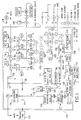
- FIG 1 shows the overall fluidic circuit diagram of the apparatus used in this invention.
- Figures 2A-C show side, top and bottom views, respectively, of a two-chamber gradient former employed as reservoir R1 in the apparatus used in this invention.
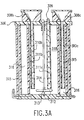
- Figures 3A-C show side, top and bottom views, respectively, of a three-chamber gradient former used as reservoir R3 in the apparatus used in this invention.
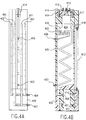
- Figures 4A-C show front, side and rear views, respectively, of the HBM used in the apparatus employed for this invention
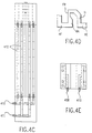
- Figure 4D shows the basic mixing unit area of the HBM
- Figure 4E shows a top view of the base of the HBM .
- Figure 5 shows the appearance of a typical protocol for introducing and removing cryoprotectant as viewed on the computer monitor during a perfusion.
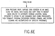
- Figures 6A-E comprise a flow chart of activities for organ cryoprotectant perfusion.
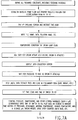
- Figures 7A-B comprise a flow chart of the procedure for non-cryoprotectant perfusions.
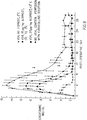
- Figure 8 shows the function (control of serum creatinine) of rabbit kidneys transplanted after perfusion with VS4.
- the apparatus incorporating the principles and features of this invention is contained in a refrigerated cabinet 100 (shown by double dashed lines in Figure 1).
- the refrigerated cabinet contains two sides, the reservoir/solenoid side and the organ/refractometer side.
- the cabinet is faced with double paned transparent doors each containing approximately 1 inch of insulating air (which can be reduced in pressure and/or humidity if necessary) between the panes to avoid condensation of moisture on the doors and to minimize heat leak to the cabinet.
- the organ-side door is split to form a "Dutch door".
- the cabinet may also employ a "Dutch door" on the reservoir side of the cabinet to enable the operator to make any needed adjustments (e.g., fluid addition to the reservoirs, transfer of upper fluid lines, etc.) without disturbing cabinet temperature to an unnecessary degree.
- lines U1-U4 can be plugged into cleaning ports C1-C4 , as indicated by the curved arrows. While this is presently done manually, it will be appreciated by those skilled in the relevant arts that appropriate valves, tubing and controls could be added to handle this task automatically.
- the reservoirs R1-R4 are supported on a thick transparent plastic shelf from which four magnetic stir tables hang which stir the four reservoirs. Thorough stirring of R1 , R3 , and R4 is necessary for proper generation of the desired concentration-time histories.
- the on/off states and stir rates of the stir tables are independently controlled.
- Ports C1-C4 lead to sources of sterile (distilled) water, air, and disinfectant.
- Solenoid valves S0 and S00 are interposed in the delivery lines for these sources and are arranged to ensure that traces of disinfectant do not enter the perfusion system by accident. Solenoid S0 controls whether air or fluid will enter the perfusion circuit for cleaning, while solenoid S00 determines whether the fluid selected will be water or disinfectant.
- Distilled water and disinfectant are drawn into the system through a sterilizing filter F4 , while air is drawn into the system through an air filter F5 .
- the disinfectant of choice at present is a clinically accepted dialysis machine cold sterilant such as Actril.
- the cleaning procedure is to wash the perfusate out of the system with water and then to displace the water with sterilant.
- the sterilant Prior to the next perfusion, the sterilant is washed out of the system with water and the water is then washed out of the system with air.
- the system is then primed by displacing the air with appropriate perfusate.
- the air flush is used to avoid the persistence of any lingering traces of sterilant dissolved in the rinse water, and to avoid any possible dilution of the priming fluid with water (i.e., to reduce the amount of priming fluid needed for displacing water from the system), to allow a visual check of the completeness of priming, and to reduce spillage of water in the cabinet when the reservoirs, filters, and organ cassette are placed into the system after cleaning but before priming.
- the air purge can, however, be omitted if desired.
- the air filter is used to prevent contamination from pathogens in the air, if necessary.
- Solenoid valves S9-S12 normally direct fluid to reservoirs R1-R4 or to waste. Reservoirs R1-R4 can also be detached from the system by removing recirculation lines RL5-RL8 from reservoirs R1-R4 and plugging them into waste ports W1-W4 , respectively (as indicated by curved arrows), allowing reservoirs R1-R4 to be removed from the system for cleaning, sterilizing, and refilling. When reservoirs R1-R4 are removed, valves S9-S12 direct fluid to waste ports W1-W4 . The four waste lines corresponding to waste ports W1-W4 converge to a single common waste line LW . A two-way solenoid valve S16 is located on the common waste line. When the waste ports are not in use, the common waste drainage line is blocked by closing valve S16 to prevent any possible backflow of waste or pathogens into the sterile cabinet.
- uptake lines U1-U4 which are plugged alternately into reservoir delivery lines D1-D4 or cleaning ports C1-C4 , in combination with recirculation lines RL5-RL8 , which are plugged alternately into the reservoir internal return lines (not shown in the figure) or into waste ports W1-W4 , allows complete sterilization of the perfusion circuit.
- the blunt ends of the uptake lines U1-U4 , delivery lines D1-D4 , cleaning ports C1-C4 and waste ports W1-W4 may be sterilized by swabbing with disinfectant when the tubing is being transferred from one alternative position to the other. The tubing transfer is accomplished while applying digital pressure to the tubing so as to occlude it while making the transfer to prevent fluid leaks and further reduce the risk of contamination.
- the fluid withdrawn from reservoirs R1-R4 or from ports C1-C4 is delivered through one of several filters F1 , F2 , and F3 , depending upon the state of actuation of solenoid valves S4 through S7 .
- filters F1 , F2 , and F3 depending upon the state of actuation of solenoid valves S4 through S7 .
- These actuation patterns will be described in more detail below.
- a single filter F1 or two filters F1 , F1' in parallel will be adequate for most studies (rendering valves S4-S7 optional, as indicated by broken lines) since virtual step changes in concentration can be imposed even when only one filter or two filters in parallel are present in the circuit.
- the filters are capable of sterilizing the perfusate and are autoclavable. All filter holders can be removed from the system for cleaning and sterilization by means of the quick disconnects shown in Figure 1.
- Vent lines V1-V3 lead to solenoid valves S13-S15 , located outside of the refrigerated portion of the cabinet 100 . These vent lines are opened and closed under computer control during priming and cleaning of the system to permit air to escape and thereby prevent the filters from becoming blocked or damaged.
- a manual bypass (shown only for the S13 bypass) is provided for V1-V3 for emergency purging of air from the circuit.
- a 90 mm diameter filter of 0.22 micron pore size is located in each filter holder.
- This size filter is able to pass enough vitrification solution at 0°C to permit the successful perfusion of a rabbit kidney, with an overlying 1.2 micron filter and a coarse prefilter to prevent clogging.
- the standard configuration for the operative version employs two identical filters in parallel. This is necessary to accommodate the flows required for human organs and provides a safety factor for any air which may be inadvertently introduced into the arterial fluid, as well as minimizing pressure building proximal to the filter.
- This continuous filter sterilization and resterilization of the perfusate during the perfusion can serve as a back up for pre-sterilized solutions in case of contamination for any reason during the perfusion.
- the fluid from the selected reservoir goes through some preliminary temperature conditioning in a heat exchanger 104 and then travels to a position as close to the organ as possible, at which point it encounters a "T" type tubing connector T1 .
- the bulk of the flow passively takes the path L1 ("refractometer loop") that leads to a flow-through process control refractometer 106 that measures the index of refraction of the liquid and hence the cryoprotectant concentration.
- the remainder of the flow is directed through an organ loop L2 by means of an organ pump 108.
- the organ pump speed is controlled by the computer so as to maintain the desired organ perfusion pressure despite wide variations in the organ's vascular resistance.
- the flow rate delivered by the circuit pump 102 which supplies both the refractometer loop L1 and the organ loop L2 , must be high enough to both exceed the flow rate through the organ at all times and to ensure that sufficient flow is available for the refractometer 106 and other in-line sensors, generally designated 110 , for measuring temperature, pH, and other desired parameters of the perfusate to permit accurate measurements.
- the flow must also be high enough to minimize the "dead time" between changes in reservoir concentration and changes in the sensed concentration and other sensed parameters in the refractometer loop as well as to minimize the "dead time" between the reservoir and the organ.
- the circuit pump flow is limited by the need to prevent fluid from being delivered to the filters at a rate in excess of what these filters or the tubing leading to them can pass without failing, as well as by constraints of beat output and wear and tear on the circuit pump tubing.
- the speed of the circuit pump is usually not varied during an experiment and does not therefore usually require computer control, though computer control is available as an option.
- the perfusate After passing through the organ pump 108 , the perfusate passes through a second heat exchanger 112 that finalizes perfusate temperature conditioning. This is done by adjusting the flow of both cold and warm liquid from cold and warm baths 114 , 116 , respectively, using computer-controlled pumps (not shown) between heat exchanger 112 and baths 114 , 116 .
- the computer is able to vary flow through both the cold path and the warm path so as to adjust perfusate temperature in the arterial line and therefore also in the effluent of the organ.
- the arterial and effluent temperatures provide an indication of the actual organ temperature.
- organ temperature can be adjusted independently of organ flow, provided flow is not close to zero.
- Generalized cabinet cooling is not an alternative to the heat exchange system for subzero perfusions because cooling of the cabinets to subzero temperatures will cause freezing of the more dilute solutions in the tubing lines.
- Specific jacketing and cooling of the organ container is of theoretical value, however, and may optionally be included.
- the temperature-conditioned perfusate is then debubbled and mixed in a bubble trap/mixer 120 just before entering an organ container 122.
- Arterial and venous temperature probes generally designated "T" in Figure 1, penetrate the wall of organ container 122 through simple holes. Pressure and, optionally, temperature is sensed in the bubble trap.
- the bubble trap and mixer 120 are in fact an integral part of the heat exchanger 112 , so heat exchange continues to be controlled while debubbling and mixing are accomplished.
- mixing is important due to the tendency for layering of dilute solutions on more concentrated, denser solutions. Details as to the specific construction of the heat exchanger/bubble trap/mixer ( HBM ) are described below.
- the cooling fluid effluent from this second heat exchanger 112 is used to cool the perfusate passing through the preliminary heat exchanger 104 .
- This cooling fluid then travels to a solenoid holding block 118 physically containing solenoids S1-S12 , so as to draw off waste heat from these solenoids before returning to the cold bath.
- the holding block 118 is equipped with an internal fluid path for drawing off waste heat from the solenoids and may be either metal or plastic.
- the solenoids are preferably 3-7 watt (or less) piston type 3-way solenoids of minimal internal fluid volume having orifices on the order of 0.156 inches or more and Cv values > 0.16 or more (e.g., NR (Neptune Research) Model 648T033 fitted with RC dropping circuits and 3-watt coils) while resisting pressures of up to 500 mmHg or so.
- Solenoids having 1/16 inch orifices and Cv values of 0.01 to 0.03 are not fully satisfactory due to the high viscosity of the solutions used for cryopreservation (causing difficulty aspirating viscous fluid through S1-S3 ), the high flows desired for controlling dead times and for perfusing larger organs, the possibility of clogging, and the buildup of pressure between the circuit pump and S8-S12 .
- the detailed actuation pattern and tubing arrangement of the solenoids is described below.
- the internal solenoids not held in the solenoid block, SR1 , SR31 and SR32 are described in more detail below.
- a stopcock (not shown) in one of the coolant lines permits the inline heat exchanger to be bypassed if desired.
- An effluent distribution block (EDB) 124 ( Figure 1) is connected to the output side of the organ container 122 .
- the EDB is designed so that a small amount of effluent is always present at the bottom of the block.
- This effluent or residual fluid is withdrawn by the two-channel "delta R.I. pump” 126 and sent to the differential refractometer ("delta R.I. meter") 130 where its refractive index is compared to that of the arterial perfusate from refractometer loop L1 (pumped at the same rate as the venous effluent sample) and a difference signal generated.
- EDB 124 is drained also by the effluent recirculation pump 128 .
- the EDB 124 therefore allows effluent to be recirculated with or without first being delivered by the delta R.I. pump 126 to a differential refractometer 130 .
- the differential refractometer 130 sends a signal to the computer which provides a measurement of the difference in concentration between the fluid in the refractometer loop L1 and the organ effluent in the organ loop L2 .
- the nonlinear baseline resulting from this unorthodox use of the differential refractometer is accounted for in the software for running the perfusion program. Since the fluid in the refractometer loop will approximate the concentration of the fluid entering the artery of the organ, the delta R.I. output provides an estimate of the arterio-venous concentration gradient across the organ. When this gradient is large (in either the positive or negative direction), the organ is far from equilibrium. When the gradient is zero, the organ is at least largely in osmotic equilibrium with the perfusate.
- the recirculation pump 128 like the circuit pump 102 , need not require flow adjustment. It is normally set to a rate sufficient to exceed the maximum steady flow through the organ pump 108 . Since the output of the recirculation pump exceeds that of the organ pump, air is continually introduced into the tubing leading to solenoid S8 and usually to the reservoirs R1-R4 . Provisions to prevent excessive bubbling of the reservoirs as a result of this are described below.
- the delta R.I. pump speed can be changed it is usually kept constant throughout an experiment. In the presently operative version, it is not under computer control, but computer control would be a desirable option in some cases.
- the delta R.I. pump employs very small diameter tubing to reduce delays in fluid transit time. This small tubing is particularly important because the flow rate through the delta R.I. circuit is limited by the lowest flow rate through the organ, which may be small, and by the limited size of the fluid paths in commercially available differential refractometers.
- the return of the differential refractometer output to the organ effluent line is proximal to the effluent recirculation pump. This placement rather than placement distal to the pump ensures a steady flow though the differential refractometer, whereas distal placement may prevent or alter differential refractometer flow by virtue of a higher exit pressure.
- the present operative version of the embodiment of the invention uses silastic tubing of 1/8 inch diameter throughout the system, which is sufficient to accommodate the needed flows and is preferred.
- Silastic is compatible with Actril cold sterilant, is translucent (important for visualizing flow to detect problems and for observing any signs of microbial growth), is impervious to common cryoprotective agents such as dimethyl sulfoxide, and is soft enough to be easily manipulated.
- cryoprotective agents such as dimethyl sulfoxide
- silastic should not be used in circuits coming into contact with silicone cooling fluids, which swell and weaken silastic tubing.
- Reservoir R1 is constructed as a gradient former ( Figure 2).
- the gradient former consists of two concentric cylinders, an outer cylinder 200 and an inner cylinder 201 .
- a fluid path 205 allows fluid to flow from the outer cylinder 200 to the inner cylinder 201 under the influence of gravity in response to a reduction of volume in the inner cylinder.
- the concentric orientation of the fluid compartments is very space efficient.
- the fluid delivery line 204 corresponds to the line D1 of Figure 1.
- the unit shown is a modification of a commercially available gradient former. The necessary modifications for use with this invention are as follows.
- Reservoir R3 is also constructed as a gradient former. The details of reservoir R3 are shown in Figure 3. In the drawing, those elements that are substantially the same as in reservoir R1 are designated with the same reference number, except that the first digit has been changed from a "2" to a "3".
- Reservoir R3 contains an outer compartment 315 ( R3 3 ), an inner compartment 318 ( R3 1 ), and a third intermediate compartment 316 ( R3 2 ).
- Intermediate compartment 316 is connected to inner compartment 318 through a fluid conduit 320 controlled by a solenoid 317 ( SR3 1 ).
- Compartment 316 also connects to outer compartment 315 by a fluid conduit 321 controlled by a solenoid 319 ( SR3 2 ).
- an outer compartment is necessary when concentration is being reduced to zero or nearly zero, for reasons noted below in the discussion of the function of the gradient pump and the action of the gradient formers.
- the outer compartment is necessary in preference to a larger volume of fluid in the middle compartment because increasing the volume of fluid in the middle compartment will cause the concentration profile of fluid flowing from the gradient former to waste in response to a constant efflux rate of inner cylinder fluid to become non-linear, therefore making control of concentration-time history more complicated. More importantly, an excessive amount of fluid in the middle compartment would be required to approach a zero concentration in the circuit compared to the amount of fluid required in the outer compartment after virtual emptying of the inner and middle compartments.
- the flow can also be partially controlled. But even with these two precautions, further control of flow is required by using an appropriate duty cycle for SR3 2 .
- the flow to R3 1 should be slow at first and more and more rapid as the concentration is brought closer and closer to zero, whereas passive flow under the influence of gravity will always be fastest at first and slowest at the end unless the flow is metered by the sort of tailored duty cycle currently being imposed on SR3 2 .
- Reservoir R4 is a gradient former constructed in the same manner as R1 .
- the gradient pump 132 connected to the circuit by a line P1 ( Figure 1).
- the function of the gradient pump is to allow for gradual changes in concentration within the appropriate reservoirs within the cabinet. The method by which this is accomplished will be described below.
- the placement of the line P1 to the gradient pump at T3A. just after the point of joining of the refractometer loop L1 and the organ loop L2 presents one option for ensures removal of some of the air introduced by the organ effluent recirculation pump 128 and therefore helps reduce bubbling of the reservoir fluid.
- a better option, however, and the one presently in use, is to draw no air into line P1 . This is accomplished by connecting P1 at point T3B and results in fully controlled concentration-time histories. The bubbling problem is then overcome by continuously regulating the speed of the recirculation pump 128 to be just slightly in excess of the combined flows of the organ pump 108 and the delta R.I. pump 126 so as to introduce little air. Attaching the recirculation output of S8 directly to P1 without regulating the speed of pump 128 results in degraded concentration history and is not recommended.
- the purpose of the gradient pump 132 is to remove some of the recirculating fluid from the circuit. This removal of fluid causes the flow rate of fluid back to the reservoir of origin to be less than the flow rate of fluid from this reservoir to the circuit. This causes the level in the inner cylinder of the reservoir ( R1 , R3 , or R4 ) to go down. This lowering of inner cylinder fluid level in turn causes the fluid in the outer or middle compartments to flow into the inner cylinder to keep the two levels similar. Thus the two dissimilar concentrations in the two cylinders are mixed in the inner cylinder, generating the concentration gradient which is then sent to the rest of the circuit. This is the manner in which the gradient pump effects the desired gradual changes in concentration which reach the organ and the refractometers. Any necessary adjustments to the gradient pump speed are made by the computer.
- the HBM heat exchange system is shown in detail in Figures 4A-E.
- the two innermost temperature control chambers 401 are used for the circulation of coolant, while the outer chambers 402 are a pathway for the flow of room temperature fluid for offsetting the coolant. (For specialized applications involving, for example, normothermic perfusion, these pathways can be reversed.)
- the direction of cold fluid flow is optional. Adequate temperature control has been found when all fluids (perfusate, coolant, and warming fluid) flow in the same direction (uphill) despite the lack of countercurrent heat exchange. This mode allows the avoidance of air or carbon dioxide accumulation in the outer chambers.
- Perfusate enters the bottom of the HBM unit through inlet 403 and travels upward in a zig zag pattern. It emerges into a small upper reservoir which has an air space above: this is the bubble trap area 404 . Perfusate then travels beneath the bubble trap and goes through a perfusate mixing area 405 before finally traveling onward to the arterial outlet.
- the inlets for cold 407 and warm 408 fluid are each split into two channels within the base of the unit.
- the outlets 410 , 411 for warm and cold fluid, respectively, each receive fluid collected from two channels such that each channel of the same kind (i.e., each cold channel or each warm channel) is the same length and nominally experiences the same pressure difference from start to finish, so that flow rate through each like channel should be approximately equal.
- All of the cold and warm fluid pathways include a length of flexible tubing 412 at the rear of the unit. These tubing segments serve two purposes. First, by introducing an air gap between the four channels, heat exchange between them is minimized. This is particularly desirable when all of the cold and warm fluid is flowing in the direction opposite to that of perfusate flow (i.e., in orthograde direction) and has not already undergone heat exchange with the perfusate. Second, each tube can be clamped. In this way, if by chance one cold channel or one warm channel should take all of the cold or warm fluid delivered while the other channel "airlocks", this situation can be corrected by clamping the channel receiving all of the flow and purging the air out of the inactive channel, bringing each channel into full function and equal flow.
- the temperature conditioning fluid enters the heat exchanging portion of the unit at the top and exits at the bottom, it is necessary upon installation to run the cold and hot pumps in retrograde direction in order to purge all air out of the cold and warm channels. This is best accomplished if the cold and warm tubing leading to and from the bath is no more than about 1/8 inch in internal diameter, since at this diameter fluid flow will displace air from the tubing rather than allowing it to flow uphill in a direction opposite to the direction of fluid flow or otherwise to remain unpurged in various parts of the tubing. Thus, when the pump direction is reversed again from retrograde to orthograde, no air will be present in the tubing and none will be trapped in the heat exchange chambers of the unit.
- the zig zag pattern is also designed to force mixing of previously perfused dense perfusate or, when perfusate density is rising rather than falling, to purge the less dense perfusate from the perfusate path.
- the zig zag pattern in fact, is also designed to allow any air bubbles to exit the heat exchange area and to emerge into the bubble trap area.
- the bubble trap area is designed to have the following features.
- the basic unit of the 3-unit mixing path is a narrow horizontal entry area HE emerging into a "wide" basal area BA which rises to an area of flow restriction FR and ends in a descent D to the next horizontal entry area.
- Fluid entering HE is forced through an opening too small to support much layering of low density fluid on top of high density fluid, especially considering the right angle turn required just before HE .
- Fluid flowing into BA may, if less dense, rise immediately upward toward FR . If more dense, it may be driven into the wall W and rise upward along this wall.
- the perfusate descends to an outlet port 406 leading directly to the organ.
- the path from the final mixing unit to port 406 is deliberately created at an angle to the horizontal in order to provide one last chance of stopping any bubbles from reaching the organ, since in order to reach the organ a bubble in this pathway would have to flow downhill, contrary to its tendency to flow uphill.
- the mixing area and subsequent areas are purged of air by occluding the outlet tubing affixed to port 406 with the vent open until approximately 1/2 inch of fluid has accumulated in the bubble trap.
- the vent is then closed until the pressure has reached about 60-120 mmHg.
- fluid is once again allowed to flow freely through port 406 .
- the jet of fluid through the mixing area and out port 406 sweeps all air out of the fluid path from the bubble trap to port 406 . If some air persists, it can be removed by repeating the process.
- the vent is opened to allow unnecessary fluid in the bubble trap to exit the trap under the influence of gravity, reaching a final depth of about 1/8 inch. A final depth of 1/8 inch cannot be set before purging the line of air because insufficient volume exists to avoid refilling the mixing area with air from the bubble trap during the purging process.
- the HBM is designed to require removal for cleaning only infrequently. Disinfection and removal of disinfectant from the bubble trap area is effected automatically but does require some operator attention afterwards to ensure that all uppermost exposed surfaces are disinfected and later washed free of disinfectant without contaminating the outlet tubes.
- the organ container comprises a rectangular box with a hinged lid, lid stop, lid handle, sloped floor, specially sloped feet, arterial and venous thermocouple inlets, perfusate inlet, and effluent outlet in the foot opposite the inlet.
- the slope of the floor is downward in both the right to left and the back to front directions to ensure that all fluid runs to the foot outlet with very little fluid accumulation anywhere in the container.
- One needle probe is inserted directly through the wall of the arterial line.
- a second probe is placed directly in the stream of fluid emerging from the organ.
- the organ container may employ a soft mesh support for the organ similar to that used in the Waters organ cassette or the organ can be placed directly on the floor of the organ container or on a specially designed independent and removable support.
- the organ container 122 and the organ pump 108 are placed in maximum proximity to reduce dead times and dead volumes between the two, and the tubing leading from the organ pump to the organ container is chosen to be as small in inner diameter as possible for the same reason.
- the modification of the refractometer sensing head appropriate for the final invention could contain the following changes from the ordinarily available Anacon unit.
- the invention allows the operator to access reservoirs in any sequence and to otherwise custom-design the process which may be of interest.
- the operator is even free to switch solenoid positions depending on what he may want to do.
- the following nominal application illustrates the actuation patterns required to deliver fluid from and to each individual reservoir and filter. It also illustrates the "standard protocols" for organ cryoprotectant perfusion and for cleaning of the system which the system was designed primarily to carry out.
- Solenoid S1 admits fluid from R1 when off, or from R2 when activated.
- Solenoid S2 is open to R3 when not energized, or to R4 when energized.
- the output of S1 and S2 is to S3 , which accepts fluid from S1 (that is, from R1 or R2 ) when in the resting state and which accepts fluid from S2 (i.e., from R3 or R4 ) when activated.
- the common outlet for S3 (always open) leads to the circuit pump 102 , which then withdraws fluid from the solenoid-selected reservoir.
- the output of the circuit pump 102 is to S4 's common port (always open).
- S4 When S4 is not energized, its output is directed to filter F1 . The return from filter F1 returns to the normally open port of S5 and exits through the S5 common outlet to the refractometer loop L1 and the organ loop L2 .
- S4 If, on the other hand, S4 is energized, then its output is directed to the common inlet port of S6 .
- S6 When S6 is in the resting state, its output is directed to filter F2 , and the return from filter F2 enters S7 through its normally open port. The output from S7 travels to the normally closed port of S5 , which must be energized to accept this output.
- Effluent from the organ eventually returns to S8 . If S8 is activated, the fluid is discarded. If S8 is not activated, the fluid is directed from S8 to combine with fluid from the refractometer loop and returned to a desired reservoir.
- Fluid traveling through the refractometer loop travels successively to solenoids S9 S10 , S11 , and S12 and then to waste if none of these solenoids are energized.
- Energizing S9 diverts flow to the R1 recirculation line.
- S10 's activation in the absence of activation of S9 ) diverts flow to R2 .
- selective activation of S11 or S12 will, respectively, recirculate fluid to R3 or R4 .
- the perfusion process typically proceeds from R1 through R4 whereas priming must occur in the reverse order to load the fluid uptake and fluid recirculation lines for reservoirs R2-R4 and, optionally filters F2 and F3 and their associated lines) while leaving the circuit primed with fluid from (typically) R1 (or C1 ) at the end of the priming (or cleaning) process.
- the typical sequence of solenoid activations required to prime the system (or to clean it) is as follows.
- priming may proceed in any order of reservoirs, provided, in the case of priming, that the final reservoir corresponds to the first reservoir used for the subsequent perfusion.
- the standard process of solenoid actuation for withdrawing fluid from R1-R4 and for creating gradients for a normal perfusion is as follows (assuming (1) use of optional filters F2 and F3 , (2) straightforward or typical use of the gradient-controlling solenoids, and (3) the existence of a gradient former as R2 ).
- the staged completion of a closed circuit upon going from one reservoir to another is to avoid recirculating solution of undesired composition to the new reservoir before its contents have displaced the previous solution from the circuit. If there is no problem with recirculating the previous solution, the precaution of delayed recirculation can be dropped.
- R1 gradient Same as 1, but activate SR1 3.
- Deliver R2 solution through F2 no + - - + + - - + - - + - - - - 5.
- Run first part of R3 gradient *** Same as 11, but activate SR31 13.
- Run second part R3 gradient Same as 11, plus SR31 and SR32 14.
- Run R4 gradient Same as 16, but activate SR4 * For normal perfusions, solenoids S0 , S00 , and S13-S16 will always be non-actuated.
- the number of reservoirs could be less than or greater than the number specified here, with corresponding changes in solenoid number. Furthermore, the number of layers of R1-R4 need not conform to the descriptions given above.
- the limits would be one reservoir at the least and perhaps eight reservoirs at the maximum, in which any reservoir could have from one to four compartments. The upper limits are based partly on volume and crowding constraints and partly on the difficulty of imagining any procedure complex enough to require more reservoirs for its control.
- Another variation would be to employ different capacity reservoirs at different positions (e.g., instead of the herein preferred embodiment, one might have a 2-liter reservoir followed by a one-liter reservoir followed by a 3-liter reservoir followed by a one-liter reservoir, and so on).
- the arterial concentration sensor could be located proximal to rather than distal to the origin of the organ loop in the circuit, but should not be located proximal to the filters.
- a pressure sensor to sense pressure developing on the circuit pump side of the filters could be incorporated as a warning device.
- the complete cryopreservation method using the above-described apparatus comprises four parts.
- the first part consists of the pretreatment of the organ prior to its removal.
- the second part is the choice of cryoprotective agents.
- the third part is the actual protocol for introducing and removing the cryoprotectant.
- the final part is treatment of the organ and the recipient upon organ transplantation.
- iloprost which is a relatively long-lived analogue of PGI 2 .
- Iloprost has been found by the present inventors to be effective in blocking the toxicity of subsequently-encountered cryoprotectant after either intravenous infusion to the systemic circulation or when given directly into the artery (or portal vein) of specific organs of interest.
- the best mode dose of iloprost appears to be 25 micrograms/kg given by either route, although direct intra-arterial infusion is presently preferred to maximize organ exposure to the agent while minimizing iloprost-mediated systemic hypotension. 15 ⁇ g/kg is also effective, but appears less effective than 25 ⁇ g/kg.
- iloprost concentration for this application are 5-75 ⁇ g/kg depending on species, infusion rate, duration of operation, etc. Iloprost is infused over the course of 20 min; acceptable infusion duration limits are 1-60 min for cadaveric organ donors. In the latter, for example, an acceptable variation would be to infuse iloprost briefly to protect the organ from the warm ischemia of organ procurement and then to compensate for brief exposure by perfusing with iloprost-containing solution at elevated or cold temperatures for a sufficient time (5-40 min). The second variation is to infuse iloprost at relatively low concentration over a relatively long time (20-60 min) so as to minimize hypotension; donor infusions for longer than 60 min are impractical.
- organs of interest are flushed in situ with cold Euro Collins solution, UW solution or a comparably effective solution either simultaneously or in a phased manner so as to stabilize all organs quickly and thereby avoid conflicts in organ procurement.
- the flushing solution(s) should initially contain iloprost (1 ⁇ g/ml in best mode, acceptable limits being 0-10 ⁇ g/ml), anticoagulants (e.g., heparin, 10,000 units/liter in the present embodiment, acceptable variations being 1,000-20,000 units/liter), vasodilators (e.g., papaverine, 40-90 mg/liter in best mode, 0-80 mg/liter as acceptable limits) and other desired agents, but a second flushing solution should be used to wash out all of these agents as cooling and blood washout is completed.
- the excised organ except for organs that are best maintained by normothermic perfusion
- Part 2 Cryoprotective Agents: Formulae of the Vitrification Solutions VS4, VS4lA, VS5, and VS5lA
- VS4 is composed of dimethyl sulfoxide (D), formamide (F), and 1,2-propanediol (P) such that the mole ratio of D to F is 1:1, the total mass of D+F+P per liter is 490 grams, and the total mass of P per liter is 150 grams.
- D + F 340 grams
- F 124.33 grams
- D 215.67 grams.
- D:F weight ratio can be as low as 1.4 and as high as 3.5; for the former, the proportion of P:(D + F) should be elevated to 18:34 and/or total concentration raised to 50-51% w/v (grams/deciliter) by addition of extra P.
- VS4 will vitrify at 1,000 atm of hydrostatic applied pressure but not at ordinary ambient pressures.
- the formula known as VS4lA is required for use at ambient pressures ("lA" refers to 1 atmosphere).
- VS41A is prepared by multiplying all VS4 constituent masses by 55/49: thus, the total concentration of solutes in VS41A is 550 grams/liter vs the 490 grams/liter of VS4.
- VS4 and VS41A appear to be particularly beneficial due to the exceptional ability of formamide to penetrate kidney tissue, the ability of dimethyl sulfoxide to block the toxicity of formamide, the beneficial balance between the three ingredients (maximizing vitrification tendency while minimizing both toxicity and total solute concentration), the lack of a colloid (typical colloid concentrations of about 4-7% w/v elevate viscosity unacceptably), the extraordinarily slow rate of devitrification of these solutions at appropriate pressures (1,000 atm and 1 atm, respectively), and the good stability of VS4lA at -135°C during at least 6 months of storage.
- the cryoprotectants used for organ perfusion are to be adjusted between the limits represented by VS4 and VS41A, depending upon the organ's tolerance to high pressures and the organ's tolerance to high cryoprotectant concentrations, so as to optimize the tradeoff between pressure and concentration required to maintain vitrifiability.
- cryoprotectant solutions must contain, in addition to the cryoprotectants themselves, slowly-penetrating solutes comprising the "carrier” or “vehicle” solution for the cryoprotectants.
- Typical examples would be UW solution, Euro Collins solution, or Renal Preservation Solution 2 (RPS-2).
- Euro Collins and possibly RPS-2 are believed to be superior to UW as carrier solutions for kidneys, whereas the opposite is likely to be true for livers, and hearts may do best with none of these particular carriers.
- the best mode process uses Euro Collins as the carrier solution of choice.
- Perfusion pressure The organ is perfused at pressures sufficient to overcome the organ's critical closing pressure but otherwise low enough to avoid needless damage to the vascular tree.
- the best mode perfusion pressure is 40 mmHg, without significant pulsation.
- a desirable range of acceptable pressures has been found to be 20-70 mmHg for different species, including man.
- initial perfusion In the best mode protocol, perfusion is first carried out for 15 min to establish baseline values for vascular resistance, to establish calibrations (for pressure and refractive index), to ensure complete blood washout, and to thermally equilibrate the organ.
- the initial perfusion time is arbitrary, and can be adjusted (from zero minutes to 1-2 days or more) to meet the requirements of the organ procurement and transportation process.
- the perfusate in this period is Euro Collins solution.
- this initial perfusate could also be UW solution or other stabilizing solution in a clinical setting depending upon the needs of the hospital or procurement team.
- Initial temperature required for organ procurement and transportation need not be identical to the perfusion temperature established just before introduction of cryoprotectant. For example, most organs may be shipped while surrounded by crushed ice at 0°C while other organs may be shipped while being perfused at normothermia (37°C). When organs are ready for cryoprotectant administration, however, a preselected, standardized perfusion temperature is established. In the best mode process, initial perfusion temperature is 3.5-4°C, and the acceptable limits are 0-15°C. The inventors consider that organs requiring normothermic perfusion for best long-term maintenance can nevertheless be cooled to within this same temperature range and treated in a manner similar to that of hypothermically-preserved organs without damage within the relatively short times required for this process.
- cryoprotectant concentration is elevated at a constant rate until a first plateau of concentration is established.
- the rate of increase in total concentration for VS4-type solutions is set to 51 mM/min (3.06 M/hr) in the best mode process, acceptable variations being 35-75 mM/min. These rates are considerably in excess of the 30 mM/min rates used by known techniques for glycerol and propylene glycol which are considered to be unnecessarily and undesirably slow for vitrification solution solutes. Linear elevation of concentration promotes equilibration without creating unnecessarily large osmotic stresses.
- the first plateau is set in the best mode process at 25% w/v total cryoprotectant (250 grams/liter, or about 3.8 molar), acceptable variations being 20-32% w/v or w/w.
- the first plateau should be set to a level that is close to half the concentration of the final vitrification solution: lower first plateau levels will increase osmotic stress upon subsequent perfusion with vitrification solution, whereas substantially higher first plateau levels will produce increased toxicity due to longer exposure times to concentrated cryoprotectant.
- the duration of the first plateau is set to 10 min in the best mode procedure, acceptable variations being 5-30 min, depending on perfusion pressure (and thus organ flow rate), vascular resistance, and organ permeability to cryoprotectant.
- the duration should be great enough to allow the organ to osmotically equilibrate with the arterial perfusate, as indicated by a zero (or virtually zero) arteriovenous concentration difference, to minimize unnecessary osmotic stress during the subsequent jump to vitrification solution.
- Temperature reduction during first concentration rise During concentration elevation, temperature is simultaneously lowered to protect the organ from chemical toxicity of the cryoprotectant. In the best mode process, temperature reduction begins as the arterial cryoprotectant concentration reaches 1.3 molar; acceptable limits are 0.5 molar to 3.5 molar. Temperature descent is terminated as the arterial concentration reaches the first concentration plateau (as noted above, 25% (3.8M) in the best mode procedure and 20-32%, or about 3-4.9 M for VS4 solutes, within the process limits). The concentration change during cooling is thus about 2.5 M in the best mode process and may vary from about 1 M to 4.4M.
- pre-cooling temperature should fall within the limits of 0-15°C.
- the temperature after cooling should fall within the range of - 13°C to +5°C. Cooling should not continue to below the freezing point of the organ.
- final temperature is presently -1.5°C, representing a fall of 5°C from the initial temperature and a cooling rate of about 0.25°C/min.
- the maximum cooling rate possible within the above limits is about 2.1 °C/min, which should be slow enough to avoid possible thermal shock to the organ.
- Minimum temperature drop during cooling is 2°C, maximum temperature drop is 28°C.
- Perfusion with vitrification solution second concentration plateau.
- a step change in concentration from the first concentration plateau to the vitrification solution is necessary to control exposure time to highly concentrated cryoprotectant.
- the concentration of vitrification solution is, as noted above, 490-550 grams/liter or about 7.5-8.4 molar for VS4-type solutions (extending as high as 600 grams/liter for hard-to-vitrify materials such as livers).
- the final concentrations may be reduced slightly, to about 480-540 grams/liter.
- the concentration limits for the present process are 40%-60% w/v cryoprotectant. Concentration is held steady at the vitrifiable concentration for 20 min in the best mode procedure, acceptable variations being 10-50 min. Concentration must be held steady sufficiently long for the removal of non-vitrifiable water from the cells and from the interstitial spaces, i.e., long enough for the organ to closely approach osmotic equilibrium with the perfusate.
- Temperature during perfusion with vitrification solution In the best mode procedure, temperature is held constant at 0 to -5°C (the temperature of choice presently being -1.5°C) as concentration rises to vitrifiable levels. Temperature constancy rather than renewed temperature descent is desirable to control viscosity: as viscosity rises with temperature reduction, effective organ resistance must also increase, reducing organ osmotic equilibration rates, necessitating increased organ exposure times to the cryoprotectant, and possibly exerting greater damage to the vascular endothelium. Lower temperatures also increase the likelihood of "chilling injury".
- an acceptable variation would be to further lower temperature as the jump to vitrification solution commences or shortly thereafter, particularly for organs perfused at or near the high temperature limits up to this point and particularly for concentrations above 49% w/v and organs that are particularly susceptible to cryoprotectant toxicity and require lower temperatures to suppress this toxicity.
- VS41A and VS5lA have freezing points close to -40°C, perfusion to temperatures this low are not included in the present process, since temperatures this low appear unnecessary, cumbersome, and most likely counterproductive.
- the low-temperature limit of the process is therefore set during vitrification solution perfusion at only -20°C and +5°C is retained as the upper limit, permitting limited additional cooling during vitrification solution perfusion.
- the next step of any practical vitrification procedure will be to remove the organ from the perfusion machine and cool it to cryogenic temperatures, with or without prior pressurization. After the organ is warmed, however, it will have to be placed back into the perfusion machine to resume the type of perfusion protocol shown in Figure 5 at the beginning of the third concentration plateau.
- First concentration reduction third concentration plateau.
- concentration at this stage should not be less than 40% (2/5) of the concentration of the vitrification solution in order to avoid osmotic damage; in the best mode process, the concentration at the third plateau is over 3/5 of the concentration at the second plateau.
- osmotic buffering agent non-penetrating extracellular low-molecular-weight solutes that counteract the osmotic effect of greater intracellular vs extracellular concentrations of cryoprotectant during the cryoprotectant efflux process
- Preferred osmotic buffering agents are raffinose or sucrose.
- Osmotic buffer concentration in the best mode 30% washout plateau solution is 250 mM.
- higher third plateau concentrations e.g., 35% w/v cryoprotectant
- less osmotic buffer is required (to a lower limit of about 150 mM).
- the presence of osmotic buffer within these limits is required to counteract the otherwise-fatal osmotic effects of a large stepwise drop in penetrating cryoprotectant concentration.
- Gradual concentration reduction to zero The next stage in the process is the gradual reduction of cryoprotectant concentration to zero or virtually zero. In the best mode process, this is carried out at a constant rate of about -43 mM/min (acceptable variations being -31 to - 65mM/min).
- Non-constant declining concentration schedules are also an acceptable variation, e.g. a linear fall at 1.5 times the average linear rate for the first third of the washout followed by a linear fall at 0.86 times the average linear rate for the second two-thirds of the washout.
- the concentration of osmotic buffer also falls in proportion, reaching a final nonzero concentration of osmotic buffer when penetrating cryoprotectant concentration reaches zero.
- This final nonzero concentration of osmotic buffer is 50 mM in the best mode process and may acceptably vary from 25 mM to 500 mM.
- absolute transmembrane osmotic forces attributable to the cryoprotectant transmembrane concentration gradient become reduced, thus reducing the requirement for osmotic buffering.
- Reducing osmotic buffer concentration during cryoprotectant washout is therefore designed to minimize osmotic damage from the osmotic buffer both during cryoprotectant washout and thereafter and is further designed to reduce potential cellular uptake of nominally non-penetrating osmotic buffering agent. No previous perfusion technique of cryoprotectant washout has ever made use of the "declining osmotic buffer principle".
- Temperature control during gradual cryoprotectant washout temperature is elevated to facilitate washout, reduce osmotic forces, and restore a perfusion temperature appropriate for an organ containing no cryoprotectant.
- temperature elevation begins as concentration falls to 4.7 molar and continues linearly with concentration drop until the initial perfusion temperature is reached when arterial concentration reaches 1.3 to 0.8 M (1°C per 0.68 to 0.78 M rise in concentration; 3.4-3.9M concentration change during warming).
- Acceptable variations for the concentration at which temperature initially rises are 2.5-5.5 M and for the concentration at which temperature rise is completed are 0.5M-4.5M.
- Osmotic buffer washout The final step in the process is to wash out the osmotic buffer.
- 50 mM sucrose is attained at the end of cryoprotectant washout.
- OB interstitial osmotic buffer
- a further problem with leaving OB in the organ for extended times before transplantation is potential leakage of OB into organ cells with consequent cellular swelling and reduced perfusion upon transplantation.
- the inventors have typically washed out 50 mM mannitol over the course of 30 min with complete success upon transplantation. Higher concentrations of OB (up to 500 mM) may be washed out over more extended times (30-90 min) that depend on perfusion resistance response to OB dilution.
- the duration of the post-washout perfusion period, comprising the osmotic buffer washout plus subsequent perfusion with no osmotic agent is adjustable to fit the logistic requirements of organ transportation and transplantation.
- Part 4 Treatment of the Organ and the Recipient at the Time of Transplantation and Thereafter
- spirin acetylsalicylate, 1-3 mg/kg
- heparin 100-250 units/kg
- the best mode concentrations are 2 mg/kg and 200 units/kg, respectively. It may also be helpful to gradually re-infuse iloprost (5-40 ⁇ g/kg, IV) beginning 5 min before clamp release and continuing for at least an additional 15 min, to obviate reperfusion injuries such as damage resulting from temporary hypoxia and inflammatory responses.
- the best mode method involves the infusion of 7-10 ⁇ g/kg of iloprost IV beginning 5 min before revascularization and continuing until 15 min after revascularization. No benefit has been observed from the use of calcium channel blockers.
- the equipment described here is capable of creating, besides organ cryoprotection protocols, a wide varitey of protocols for conventional organ hypothermic and normothermic preservation.
- a wide variety of normothermic pharmacological, physiological, and pathophysiological protocols are possible.
- the present inventors exeplify many of these possibilities by describing the steps required to carry out many of these protocols in Figures 7A-7B, which are self-explanatory.
- Figure 8 shows post-operative serum creatinines of rabbits receiving kidneys previously perfused with VS4 in Euro-Collins solution.
- organs Prior to procurement, organs were treated in vivo with zero, 15, and 25 ⁇ g/kg of iloprost given by systemic intravenous infusion over a 20-minute period.
- Kidneys in these three groups were exposed to VS4 at +2, 0-2, and -1 to - 6°C, respectively. Initial and final perfusion temperatures were 2°C in all cases.
- Rabbit survivals in these three groups were 5/16 (31%), 6/10 (60%), and 10/10 (100%), respectively. Only data for rabbits surviving the first night after surgery are included.
Landscapes
- Life Sciences & Earth Sciences (AREA)
- Health & Medical Sciences (AREA)
- Engineering & Computer Science (AREA)
- Dentistry (AREA)
- General Health & Medical Sciences (AREA)
- Wood Science & Technology (AREA)
- Zoology (AREA)
- Environmental Sciences (AREA)
- Agricultural Chemicals And Associated Chemicals (AREA)
- Micro-Organisms Or Cultivation Processes Thereof (AREA)
- External Artificial Organs (AREA)
Applications Claiming Priority (3)
| Application Number | Priority Date | Filing Date | Title |
|---|---|---|---|
| US725054 | 1991-07-08 | ||
| US07/725,054 US5217860A (en) | 1991-07-08 | 1991-07-08 | Method for preserving organs for transplantation by vitrification |
| EP19920915604 EP0594733A4 (de) | 1991-07-08 | 1992-07-07 | Computer gesteuerte apparatur und methode zur perfusion mit gefrierschutzmittel. |
Related Parent Applications (2)
| Application Number | Title | Priority Date | Filing Date |
|---|---|---|---|
| EP19920915604 Division EP0594733A4 (de) | 1991-07-08 | 1992-07-07 | Computer gesteuerte apparatur und methode zur perfusion mit gefrierschutzmittel. |
| EP92915604.0 Division | 1993-01-28 |
Publications (3)
| Publication Number | Publication Date |
|---|---|
| EP0800765A2 true EP0800765A2 (de) | 1997-10-15 |
| EP0800765A3 EP0800765A3 (de) | 1998-04-08 |
| EP0800765B1 EP0800765B1 (de) | 2000-05-24 |
Family
ID=24912973
Family Applications (2)
| Application Number | Title | Priority Date | Filing Date |
|---|---|---|---|
| EP19920915604 Ceased EP0594733A4 (de) | 1991-07-08 | 1992-07-07 | Computer gesteuerte apparatur und methode zur perfusion mit gefrierschutzmittel. |
| EP97107891A Expired - Lifetime EP0800765B1 (de) | 1991-07-08 | 1992-07-07 | Verfahren zur Vorbereitung von Organen auf Langzeitkonservierung und Transplantation |
Family Applications Before (1)
| Application Number | Title | Priority Date | Filing Date |
|---|---|---|---|
| EP19920915604 Ceased EP0594733A4 (de) | 1991-07-08 | 1992-07-07 | Computer gesteuerte apparatur und methode zur perfusion mit gefrierschutzmittel. |
Country Status (7)
| Country | Link |
|---|---|
| US (2) | US5217860A (de) |
| EP (2) | EP0594733A4 (de) |
| JP (1) | JPH07500815A (de) |
| AT (1) | ATE193181T1 (de) |
| CA (1) | CA2113119C (de) |
| DE (1) | DE69231106T2 (de) |
| WO (1) | WO1993000808A1 (de) |
Cited By (1)
| Publication number | Priority date | Publication date | Assignee | Title |
|---|---|---|---|---|
| US20160298077A1 (en) * | 2013-07-02 | 2016-10-13 | Austrianova Singapore Pte Ltd. | A method of freeze-drying encapsulated cells, freeze-dried encapsulated cells, compositions containing freeze-dried encapsulated cells and uses of such cells and compositions |
Families Citing this family (167)
| Publication number | Priority date | Publication date | Assignee | Title |
|---|---|---|---|---|
| US5827222A (en) * | 1990-10-10 | 1998-10-27 | Life Resuscitation Technologies, Inc. | Method of treating at least one of brain and associated nervous tissue injury |
| US5584804A (en) * | 1990-10-10 | 1996-12-17 | Life Resuscitation Technologies, Inc. | Brain resuscitation and organ preservation device and method for performing the same |
| US5856081A (en) * | 1991-07-08 | 1999-01-05 | The American National Red Cross | Computer controlled cryoprotectant perfusion apparatus |
| US5723282A (en) | 1991-07-08 | 1998-03-03 | The American National Red Cross | Method of preparing organs for vitrification |
| US5338662A (en) * | 1992-09-21 | 1994-08-16 | Bio-Preserve Medical Corporation | Organ perfusion device |
| US6161543A (en) * | 1993-02-22 | 2000-12-19 | Epicor, Inc. | Methods of epicardial ablation for creating a lesion around the pulmonary veins |
| US5356771A (en) * | 1993-03-11 | 1994-10-18 | Board Of Regents, The University Of Texas System | Combined perfusion and oxygenation organ preservation apparatus |
| US5362622A (en) * | 1993-03-11 | 1994-11-08 | Board Of Regents, The University Of Texas System | Combined perfusion and oxygenation apparatus |
| US7138500B1 (en) * | 1993-05-07 | 2006-11-21 | Immunex Corporation | Antibodies to human 4-1BB |
| DE9422008U1 (de) * | 1993-06-07 | 1997-08-28 | Mayer, Berndt, Priv.-Doz. Dr.med., 10585 Berlin | Vorrichtung zur Konservierung von Organen, Extremitäten und Gewebelappen |
| KR950030791A (ko) * | 1994-01-25 | 1995-12-18 | 아키요 시게마주 | 생물조직 보존방법 및 그를 위한 관류액 |
| ATE423464T1 (de) * | 1994-05-20 | 2009-03-15 | Breonics Inc | Verfahren zur überwachung der lebensfähigkeit transplantabler organe |
| US5897553A (en) | 1995-11-02 | 1999-04-27 | Medtronic, Inc. | Ball point fluid-assisted electrocautery device |
| US6409722B1 (en) | 1998-07-07 | 2002-06-25 | Medtronic, Inc. | Apparatus and method for creating, maintaining, and controlling a virtual electrode used for the ablation of tissue |
| AU5375496A (en) * | 1995-03-27 | 1996-10-16 | American National Red Cross, The | Organ evaluation and resuscitation device and method |
| US5586438A (en) * | 1995-03-27 | 1996-12-24 | Organ, Inc. | Portable device for preserving organs by static storage or perfusion |
| AU5382396A (en) * | 1995-03-31 | 1996-10-16 | Life Resuscitation Technologies, Inc. | Histological processing device and method |
| USD391372S (en) | 1995-04-17 | 1998-02-24 | Joseph Scelza | Continuous perfusion tissue culture apparatus |
| WO1996039819A1 (en) * | 1995-06-07 | 1996-12-19 | St. Jude Medical, Inc. | Cardiovascular bioreactor apparatus and method |
| DE19527734A1 (de) * | 1995-07-28 | 1997-01-30 | Hubert Verhaag | Verfahren und Vorrichtung zur Konservierung von Geweben und Organen, insbesondere von Transplantationsgeweben und -organen |
| TR199801066T2 (xx) * | 1995-12-15 | 1998-08-21 | Cryopreservation Technologies Cc | Organ kriyokorumas� ve viral ve bakteryal enfeksiyonlar�n iyile�tirilmesi i�in bile�im. |
| NL1003024C2 (nl) | 1996-05-03 | 1997-11-06 | Tjong Hauw Sie | Prikkelgeleidingsblokkeringsinstrument. |
| JP2001502664A (ja) * | 1996-09-06 | 2001-02-27 | ユニバーサル プリザーベーション テクノロジーズ,インコーポレイテッド | 細胞、組織、器官及び生物体の貯蔵保存用ガラス化溶液 |
| AU5251698A (en) * | 1996-11-07 | 1998-05-29 | 21St Century Medicine, Inc. | A method for rapid cooling and warming of biological materials |
| US6642045B1 (en) | 1997-04-14 | 2003-11-04 | Breonics, Inc. | System for exsanguinous metabolic support of an organ or tissue |
| US5834178C1 (en) * | 1997-07-09 | 2002-04-23 | Univ Wayne State | Flush-storage solution for donor organs |
| US6096037A (en) | 1997-07-29 | 2000-08-01 | Medtronic, Inc. | Tissue sealing electrosurgery device and methods of sealing tissue |
| US8409846B2 (en) | 1997-09-23 | 2013-04-02 | The United States Of America As Represented By The Department Of Veteran Affairs | Compositions, methods and devices for maintaining an organ |
| US6100082A (en) * | 1997-09-23 | 2000-08-08 | Hassanein; Waleed H. | Perfusion apparatus and method including chemical compositions for maintaining an organ |
| US6485450B1 (en) | 1998-03-16 | 2002-11-26 | Life Science Holdings, Inc. | Brain resuscitation apparatus and method |
| US6673008B1 (en) | 1998-04-28 | 2004-01-06 | Ronald J. Thompson | Fallopian tube and method of in vitro fertilization and embryo development |
| US6537248B2 (en) * | 1998-07-07 | 2003-03-25 | Medtronic, Inc. | Helical needle apparatus for creating a virtual electrode used for the ablation of tissue |
| US6706039B2 (en) | 1998-07-07 | 2004-03-16 | Medtronic, Inc. | Method and apparatus for creating a bi-polar virtual electrode used for the ablation of tissue |
| US6977140B1 (en) * | 1998-09-29 | 2005-12-20 | Organ Recovery Systems, Inc. | Method for maintaining and/or restoring viability of organs |
| US6673594B1 (en) | 1998-09-29 | 2004-01-06 | Organ Recovery Systems | Apparatus and method for maintaining and/or restoring viability of organs |
| JP2002525290A (ja) | 1998-09-29 | 2002-08-13 | オーガン リカヴァリー システムス インコーポレイテッド | 器官の生存度を維持し及び/又は回復させる装置及び方法 |
| US7749693B2 (en) * | 1998-09-29 | 2010-07-06 | Lifeline Scientific, Inc. | Method of determining that an organ is not suitable for transplantation and using it for testing substances |
| CA2877233A1 (en) | 1999-01-19 | 2000-07-27 | Lola M. Reid | Human liver progenitors |
| US6194137B1 (en) | 1999-04-13 | 2001-02-27 | Organ Recovery Systems, Inc. | Method of cryopreservation of blood vessels by vitrification |
| US20070166292A1 (en) * | 1999-04-14 | 2007-07-19 | Breonics, Inc. | System for exsanguinous metabolic support of an organ or tissue |
| US6582953B2 (en) | 1999-04-14 | 2003-06-24 | Breonics, Inc. | Organ chamber for exsanguinous metabolic support system |
| CA2847723A1 (en) * | 1999-04-14 | 2000-10-19 | Breonics, Inc. | System for exsanguinous metabolic support of an organ or tissue |
| US6567679B1 (en) * | 1999-05-28 | 2003-05-20 | E-Monitors, Inc. | Method of using a pH tissue monitor |
| US20030040665A1 (en) * | 1999-05-28 | 2003-02-27 | E-Monitors, Inc. | Systems and methods of pH tissue monitoring |
| US20070048726A1 (en) * | 2000-01-14 | 2007-03-01 | Biolife Solutions, Inc. | Methods and Compositions for the Control of Molecular-Based Cell Death During Preservation of Cells, Tissues or Organs in a Gel-Like State |
| US7706882B2 (en) | 2000-01-19 | 2010-04-27 | Medtronic, Inc. | Methods of using high intensity focused ultrasound to form an ablated tissue area |
| US8241274B2 (en) | 2000-01-19 | 2012-08-14 | Medtronic, Inc. | Method for guiding a medical device |
| US6447443B1 (en) | 2001-01-13 | 2002-09-10 | Medtronic, Inc. | Method for organ positioning and stabilization |
| US6692450B1 (en) | 2000-01-19 | 2004-02-17 | Medtronic Xomed, Inc. | Focused ultrasound ablation devices having selectively actuatable ultrasound emitting elements and methods of using the same |
| US8221402B2 (en) | 2000-01-19 | 2012-07-17 | Medtronic, Inc. | Method for guiding a medical device |
| US8083736B2 (en) | 2000-03-06 | 2011-12-27 | Salient Surgical Technologies, Inc. | Fluid-assisted medical devices, systems and methods |
| US8048070B2 (en) | 2000-03-06 | 2011-11-01 | Salient Surgical Technologies, Inc. | Fluid-assisted medical devices, systems and methods |
| FR2807827B1 (fr) * | 2000-04-12 | 2002-07-05 | Technomed Medical Systems | Systeme de manipulation de fluide pour appareil de therapie |
| EP1278471B1 (de) | 2000-04-27 | 2005-06-15 | Medtronic, Inc. | Vibrationsempfindliche ablationsvorrichtung |
| US6488680B1 (en) | 2000-04-27 | 2002-12-03 | Medtronic, Inc. | Variable length electrodes for delivery of irrigated ablation |
| US6514250B1 (en) | 2000-04-27 | 2003-02-04 | Medtronic, Inc. | Suction stabilized epicardial ablation devices |
| WO2002014480A2 (en) * | 2000-08-16 | 2002-02-21 | Duke University | Decellularized tissue engineered constructs and tissues |
| WO2002017714A2 (en) * | 2000-08-25 | 2002-03-07 | Organ Recovery Systems, Inc. | Methods of thrombolytic organ treatment and repair |
| US6926669B1 (en) | 2000-10-10 | 2005-08-09 | Medtronic, Inc. | Heart wall ablation/mapping catheter and method |
| CN100381048C (zh) * | 2000-11-03 | 2008-04-16 | 维特罗莱夫股份公司 | 评价和保存溶液 |
| US20040138621A1 (en) | 2003-01-14 | 2004-07-15 | Jahns Scott E. | Devices and methods for interstitial injection of biologic agents into tissue |
| US7628780B2 (en) | 2001-01-13 | 2009-12-08 | Medtronic, Inc. | Devices and methods for interstitial injection of biologic agents into tissue |
| US7740623B2 (en) | 2001-01-13 | 2010-06-22 | Medtronic, Inc. | Devices and methods for interstitial injection of biologic agents into tissue |
| US7959626B2 (en) * | 2001-04-26 | 2011-06-14 | Medtronic, Inc. | Transmural ablation systems and methods |
| US7250048B2 (en) | 2001-04-26 | 2007-07-31 | Medtronic, Inc. | Ablation system and method of use |
| US6663627B2 (en) | 2001-04-26 | 2003-12-16 | Medtronic, Inc. | Ablation system and method of use |
| US6648883B2 (en) | 2001-04-26 | 2003-11-18 | Medtronic, Inc. | Ablation system and method of use |
| US6807968B2 (en) | 2001-04-26 | 2004-10-26 | Medtronic, Inc. | Method and system for treatment of atrial tachyarrhythmias |
| US6699240B2 (en) | 2001-04-26 | 2004-03-02 | Medtronic, Inc. | Method and apparatus for tissue ablation |
| US8580487B2 (en) * | 2001-05-29 | 2013-11-12 | Core Dynamics Limited | Methods of preserving functionality of an organ, preserving fertility of a patient undergoing a treatment expected to cause sterility and assuring a supply of viable gametes for future use |
| WO2002101018A2 (en) * | 2001-06-11 | 2002-12-19 | Fred Hutchinson Cancer Research Center | Methods for inducing reversible stasis |
| US6677150B2 (en) | 2001-09-14 | 2004-01-13 | Organ Transport Systems, Inc. | Organ preservation apparatus and methods |
| US6656175B2 (en) | 2001-12-11 | 2003-12-02 | Medtronic, Inc. | Method and system for treatment of atrial tachyarrhythmias |
| US6827715B2 (en) | 2002-01-25 | 2004-12-07 | Medtronic, Inc. | System and method of performing an electrosurgical procedure |
| US7967816B2 (en) | 2002-01-25 | 2011-06-28 | Medtronic, Inc. | Fluid-assisted electrosurgical instrument with shapeable electrode |
| US7118566B2 (en) | 2002-05-16 | 2006-10-10 | Medtronic, Inc. | Device and method for needle-less interstitial injection of fluid for ablation of cardiac tissue |
| US7294143B2 (en) | 2002-05-16 | 2007-11-13 | Medtronic, Inc. | Device and method for ablation of cardiac tissue |
| US7572622B2 (en) * | 2002-08-14 | 2009-08-11 | Transmedic, Inc. | Heart preservation chamber |
| ATE363233T1 (de) * | 2002-08-23 | 2007-06-15 | Organ Recovery Systems | Verbindungsanordnungen, insbesondere für transplantationsorgane |
| AU2002330726A1 (en) * | 2002-08-28 | 2004-03-19 | I.M.T. Interface Multigrad Technology Ltd | Methods of preserving the functionality of an organ. |
| US7083620B2 (en) | 2002-10-30 | 2006-08-01 | Medtronic, Inc. | Electrosurgical hemostat |
| US6921633B2 (en) * | 2002-11-18 | 2005-07-26 | Biolife Solutions Incorporated | Methods and compositions for the preservation of cells, tissues or organs in the vitreous state |
| USD531319S1 (en) | 2003-04-04 | 2006-10-31 | Organ Recovery Systems | Tube frame for organ transporter |
| US7678563B2 (en) | 2003-04-04 | 2010-03-16 | Organ Recovery Systems, Inc. | Method and apparatus for controlling air pressure in an organ or tissue container |
| USD531320S1 (en) | 2003-04-04 | 2006-10-31 | Organ Recovery Systems | Cassette for organ transporter |
| WO2004089085A2 (en) * | 2003-04-04 | 2004-10-21 | Organ Recovery Systems, Inc. | Device for separating gas from a liquid path |
| US7497857B2 (en) | 2003-04-29 | 2009-03-03 | Medtronic, Inc. | Endocardial dispersive electrode for use with a monopolar RF ablation pen |
| US7897327B2 (en) * | 2003-06-02 | 2011-03-01 | Organ Recovery Systems, Inc. | Method and apparatus for pressure control for maintaining viability of organs |
| AT414254B (de) * | 2003-06-05 | 2006-10-15 | Kaindl Flooring Gmbh | Verkleidungsplatte |
| US7278278B2 (en) | 2003-06-12 | 2007-10-09 | 21St Century Medicine, Inc. | Cryogenic storage system |
| JP2007509163A (ja) | 2003-10-22 | 2007-04-12 | フレッド ハッチンソン キャンサー リサーチ センター | 組織および臓器においてスタシスを誘導する方法、組成物、および装置 |
| US7504201B2 (en) * | 2004-04-05 | 2009-03-17 | Organ Recovery Systems | Method for perfusing an organ and for isolating cells from the organ |
| US8333764B2 (en) | 2004-05-12 | 2012-12-18 | Medtronic, Inc. | Device and method for determining tissue thickness and creating cardiac ablation lesions |
| US8741555B2 (en) * | 2004-05-14 | 2014-06-03 | Organ Recovery Systems, Inc. | Apparatus and method for perfusion and determining the viability of an organ |
| WO2005112812A1 (en) | 2004-05-14 | 2005-12-01 | Medtronic, Inc. | Method and devices for treating atrial fibrillation by mass ablation |
| WO2005120375A2 (en) | 2004-06-02 | 2005-12-22 | Medtronic, Inc. | Loop ablation apparatus and method |
| EP1750606B1 (de) | 2004-06-02 | 2010-05-05 | Medtronic, Inc. | Zusammengesetzte bipolare ablationsvorrichtung |
| EP1750608B1 (de) | 2004-06-02 | 2012-10-03 | Medtronic, Inc. | Ablationsvorrichtung mit backen |
| WO2005120377A1 (en) | 2004-06-02 | 2005-12-22 | Medtronic, Inc. | Clamping ablation tool |
| US8409219B2 (en) | 2004-06-18 | 2013-04-02 | Medtronic, Inc. | Method and system for placement of electrical lead inside heart |
| US8663245B2 (en) | 2004-06-18 | 2014-03-04 | Medtronic, Inc. | Device for occlusion of a left atrial appendage |
| US8926635B2 (en) | 2004-06-18 | 2015-01-06 | Medtronic, Inc. | Methods and devices for occlusion of an atrial appendage |
| US8028438B2 (en) * | 2004-07-02 | 2011-10-04 | Aqualizer, Llc | Moisture condensation control system |
| US12010987B2 (en) | 2004-10-07 | 2024-06-18 | Transmedics, Inc. | Systems and methods for ex-vivo organ care and for using lactate as an indication of donor organ status |
| US9301519B2 (en) * | 2004-10-07 | 2016-04-05 | Transmedics, Inc. | Systems and methods for ex-vivo organ care |
| US8304181B2 (en) | 2004-10-07 | 2012-11-06 | Transmedics, Inc. | Method for ex-vivo organ care and for using lactate as an indication of donor organ status |
| ATE470354T1 (de) * | 2004-10-07 | 2010-06-15 | Transmedics Inc | Systeme und verfahren für die ex-vivo-organpflege |
| US9078428B2 (en) | 2005-06-28 | 2015-07-14 | Transmedics, Inc. | Systems, methods, compositions and solutions for perfusing an organ |
| US10176887B1 (en) | 2005-11-14 | 2019-01-08 | Organ Recovery Systems, Inc. | Ex vivo methods for drug discovery, development and testing |
| US20100233670A1 (en) * | 2006-02-13 | 2010-09-16 | Zohar Gavish | Frozen Viable Solid Organs and Method for Freezing Same |
| ES2625850T3 (es) * | 2006-04-19 | 2017-07-20 | Transmedics, Inc. | Procedimientos para el cuidado de órganos ex vivo |
| US20080039746A1 (en) | 2006-05-25 | 2008-02-14 | Medtronic, Inc. | Methods of using high intensity focused ultrasound to form an ablated tissue area containing a plurality of lesions |
| CN101677526B (zh) | 2007-03-01 | 2014-07-09 | 生命线科学有限公司 | 灌注调节 |
| US9457179B2 (en) | 2007-03-20 | 2016-10-04 | Transmedics, Inc. | Systems for monitoring and applying electrical currents in an organ perfusion system |
| US8765364B2 (en) * | 2007-05-18 | 2014-07-01 | Lifeline Scientific, Inc. | Ex vivo methods for validating substance testing with human organs and/or tissues |
| US8771930B2 (en) * | 2007-05-18 | 2014-07-08 | Lifeline Scientific, Inc. | Ex vivo methods for testing toxicity of substances using donated human organs or tissues |
| WO2009003061A1 (en) | 2007-06-25 | 2008-12-31 | Fred Hutchinson Cancer Research Center | Methods and compositions regarding polychalcogenide compositions |
| US7960098B2 (en) * | 2007-07-12 | 2011-06-14 | Warsaw Orthoperic, Inc. | Methods and compositions for the preservation of cells and tissues |
| US7892724B2 (en) * | 2007-07-12 | 2011-02-22 | Warsaw Orthopedic, Inc | Method for enhancing the viability of mammalian cells, tissues and organs using a solution comprising two low molecular weight PEGs |
| US8882756B2 (en) | 2007-12-28 | 2014-11-11 | Medtronic Advanced Energy Llc | Fluid-assisted electrosurgical devices, methods and systems |
| US9247728B2 (en) | 2008-01-31 | 2016-02-02 | Transmedics, Inc. | Systems and methods for ex vivo lung care |
| WO2009140359A2 (en) | 2008-05-13 | 2009-11-19 | Medtronic, Inc. | Tissue lesion evaluation |
| KR20110043580A (ko) * | 2008-07-02 | 2011-04-27 | 가부시키가이샤 오츠까 세이야꾸 고죠 | 인공 신장 전구체 및 그 제조 방법 |
| US9254168B2 (en) | 2009-02-02 | 2016-02-09 | Medtronic Advanced Energy Llc | Electro-thermotherapy of tissue using penetrating microelectrode array |
| WO2010096809A1 (en) | 2009-02-23 | 2010-08-26 | Salient Surgical Technologies, Inc. | Fluid-assisted electrosurgical device and methods of use thereof |
| CN102438445B (zh) * | 2009-02-23 | 2014-12-10 | 细胞与组织系统股份有限公司 | 组织的无冰低温贮藏法 |
| CN102497832B (zh) | 2009-09-08 | 2015-09-09 | 显著外科技术公司 | 用于电外科装置、电外科器械的盒组件及其使用方法 |
| WO2011112991A1 (en) | 2010-03-11 | 2011-09-15 | Salient Surgical Technologies, Inc. | Bipolar electrosurgical cutter with position insensitive return electrode contact |
| US20110295249A1 (en) * | 2010-05-28 | 2011-12-01 | Salient Surgical Technologies, Inc. | Fluid-Assisted Electrosurgical Devices, and Methods of Manufacture Thereof |
| US9138289B2 (en) | 2010-06-28 | 2015-09-22 | Medtronic Advanced Energy Llc | Electrode sheath for electrosurgical device |
| US8920417B2 (en) | 2010-06-30 | 2014-12-30 | Medtronic Advanced Energy Llc | Electrosurgical devices and methods of use thereof |
| US8906012B2 (en) | 2010-06-30 | 2014-12-09 | Medtronic Advanced Energy Llc | Electrosurgical devices with wire electrode |
| US12082575B2 (en) | 2010-09-01 | 2024-09-10 | Organ Transport Pty Ltd | Perfusion solution |
| US9023040B2 (en) | 2010-10-26 | 2015-05-05 | Medtronic Advanced Energy Llc | Electrosurgical cutting devices |
| WO2012078968A2 (en) | 2010-12-10 | 2012-06-14 | Lifeline Scientific, Inc. | Machine perfusion with complement inhibitors |
| US9427281B2 (en) | 2011-03-11 | 2016-08-30 | Medtronic Advanced Energy Llc | Bronchoscope-compatible catheter provided with electrosurgical device |
| CN106342788B (zh) | 2011-04-14 | 2020-03-17 | 特兰斯迈迪茨公司 | 用于供体肺的离体机器灌注的器官护理溶液 |
| US8828034B2 (en) | 2011-04-29 | 2014-09-09 | Lifeline Scientific, Inc. | Cannula |
| US9022978B2 (en) | 2011-04-29 | 2015-05-05 | Lifeline Scientific, Inc. | Universal sealring cannula |
| US9642625B2 (en) | 2011-04-29 | 2017-05-09 | Lifeline Scientific, Inc. | Cannula for a donor organ with or without an aortic cuff or patch |
| US9750565B2 (en) | 2011-09-30 | 2017-09-05 | Medtronic Advanced Energy Llc | Electrosurgical balloons |
| US8870864B2 (en) | 2011-10-28 | 2014-10-28 | Medtronic Advanced Energy Llc | Single instrument electrosurgery apparatus and its method of use |
| EP2809153B8 (de) | 2012-01-17 | 2023-07-12 | Tevosol, Inc. | Vorrichtung zum testen, zur beurteilung und zur bewahrung von explantierten herzen für eine transplantation |
| US9565853B2 (en) * | 2012-07-10 | 2017-02-14 | Lifeline Scientific, Inc. | Perfusion apparatus with reduced pressure fluctuations, and bubble trap |
| US9119393B2 (en) | 2012-07-10 | 2015-09-01 | Lifeline Scientific, Inc. | Organ transporter with tilt and/or shock sensing |
| US20140017666A1 (en) | 2012-07-10 | 2014-01-16 | Lifeline Scientific, Inc. | Filtration in organ perfusion apparatus |
| US9259562B2 (en) | 2012-07-10 | 2016-02-16 | Lifeline Scientific, Inc. | Cannula |
| US10823743B1 (en) | 2013-10-28 | 2020-11-03 | Ifirst Medical Technologies, Inc. | Methods of measuring coagulation of a biological sample |
| ES3036002T3 (en) * | 2014-03-26 | 2025-09-11 | Transmedics Inc | Apparatus for maintenance of harvested hearts for transplanting |
| EP3151663B1 (de) | 2014-06-02 | 2020-09-23 | Transmedics, Inc. | Ex-vivo-organpflege system |
| US9974599B2 (en) | 2014-08-15 | 2018-05-22 | Medtronic Ps Medical, Inc. | Multipurpose electrosurgical device |
| EP3229588B1 (de) | 2014-12-12 | 2025-04-23 | TransMedics, Inc. | Vorrichtung und verfahren zur organperfusion |
| US11389227B2 (en) | 2015-08-20 | 2022-07-19 | Medtronic Advanced Energy Llc | Electrosurgical device with multivariate control |
| US11051875B2 (en) | 2015-08-24 | 2021-07-06 | Medtronic Advanced Energy Llc | Multipurpose electrosurgical device |
| CA2997267A1 (en) | 2015-09-09 | 2017-03-16 | Transmedics, Inc. | Aortic cannula for ex vivo organ care system |
| US10716612B2 (en) | 2015-12-18 | 2020-07-21 | Medtronic Advanced Energy Llc | Electrosurgical device with multiple monopolar electrode assembly |
| ES2968415T3 (es) * | 2016-02-09 | 2024-05-09 | Sun Pharmaceutical Ind Ltd | Sistema de perfusión |
| DK3462861T5 (da) | 2016-05-30 | 2024-01-08 | Transmedics Inc | Fremgangsmåde til ex vivo-lungeventilati on med et varierende udvendigt tryk |
| US10194975B1 (en) | 2017-07-11 | 2019-02-05 | Medtronic Advanced Energy, Llc | Illuminated and isolated electrosurgical apparatus |
| FR3069135B1 (fr) * | 2017-07-20 | 2020-10-30 | Centre De Rech Biologiques Et Dexperimentations Cutanees | Dispositif de maintien en survie d'un explant |
| US12023082B2 (en) | 2017-10-06 | 2024-07-02 | Medtronic Advanced Energy Llc | Hemostatic thermal sealer |
| AU2019385712B2 (en) * | 2018-11-22 | 2025-10-02 | Vitrafy Life Sciences Limited | Method and apparatus for freezing of biological products |
| US11596146B2 (en) * | 2019-06-20 | 2023-03-07 | Joseph Mario Bernaudo | Speed controlled centrifugal pump embalming systems and method of using the same |
| EP4097471A4 (de) | 2020-01-29 | 2024-07-03 | Ifirst Medical Technologies, Inc. | Medizinischer analysator und profiler für diagnostische proben |
| AU2021253251A1 (en) | 2020-04-08 | 2022-12-08 | Vitrafy Life Sciences Limited | Method and apparatus for freezing of consumable products |
| AU2021419389A1 (en) * | 2021-01-14 | 2023-08-17 | Vitrafy Life Sciences Limited | Method and apparatus for preservation of biological material |
| EP4369928A1 (de) * | 2021-07-15 | 2024-05-22 | Sorin Group Italia S.r.l. | Organperfusions- und konservierungssystem und -verfahren |
Family Cites Families (21)
| Publication number | Priority date | Publication date | Assignee | Title |
|---|---|---|---|---|
| US3772153A (en) * | 1969-04-02 | 1973-11-13 | Air Liquide | Apparatus for the preservation of animal or human organs in living condition |
| US3892628A (en) * | 1969-10-06 | 1975-07-01 | Baxter Laboratories Inc | Preservation of organs |
| US3639084A (en) * | 1970-04-06 | 1972-02-01 | Baxter Laboratories Inc | Mechanism for control pulsatile fluid flow |
| US3753865A (en) * | 1971-03-12 | 1973-08-21 | Univ California | Method and apparatus for preserving human organs extracorporeally |
| DE2241698C2 (de) * | 1971-09-02 | 1982-08-26 | Roland Dr.med. Zürich Doerig | Verfahren zur Organerhaltung sowie Vorrichtung zum Durchführen dieses Verfahrens |
| US3843455A (en) * | 1972-09-13 | 1974-10-22 | M Bier | Apparatus and technique for preservation of isolated organs through perfusion |
| US3995444A (en) * | 1974-11-08 | 1976-12-07 | American Hospital Supply Corporation | Organ perfusion system |
| US4186565A (en) * | 1978-05-19 | 1980-02-05 | Henry Ford Hospital | Perfusion system for organ preservation |
| US4629686A (en) * | 1982-02-19 | 1986-12-16 | Endotronics, Inc. | Apparatus for delivering a controlled dosage of a chemical substance |
| US4559298A (en) * | 1982-11-23 | 1985-12-17 | American National Red Cross | Cryopreservation of biological materials in a non-frozen or vitreous state |
| US4618586A (en) * | 1983-04-08 | 1986-10-21 | Endotronics, Inc. | Apparatus for administering a controlled dosage of a chemical substance having an improved culture chamber |
| US4837390A (en) * | 1983-05-11 | 1989-06-06 | Keyes Offshore, Inc. | Hyperbaric organ preservation apparatus and method for preserving living organs |
| US4471629A (en) * | 1983-05-31 | 1984-09-18 | Mount Carmel Research And Education Corporation | Method of freezing and transplant of kidneys and apparatus |
| US4798824A (en) * | 1985-10-03 | 1989-01-17 | Wisconsin Alumni Research Foundation | Perfusate for the preservation of organs |
| US4879283A (en) * | 1985-10-03 | 1989-11-07 | Wisconsin Alumni Research Foundation | Solution for the preservation of organs |
| US4688387A (en) * | 1985-11-12 | 1987-08-25 | Vital Force, Inc. | Method for preservation and storage of viable biological materials at cryogenic temperatures |
| US4704029A (en) * | 1985-12-26 | 1987-11-03 | Research Corporation | Blood glucose monitor |
| US4745759A (en) * | 1986-12-23 | 1988-05-24 | Bauer Dan O | Kidney preservation machine |
| WO1988005261A1 (en) * | 1987-01-16 | 1988-07-28 | Tops Systems, Inc. | Total organ perfusion system |
| US5051352A (en) * | 1987-10-07 | 1991-09-24 | The Regents Of The University Of California | Apparatus and method of preserving the viability of animal organs |
| JPH0653160B2 (ja) * | 1989-08-18 | 1994-07-20 | 呉羽化学工業株式会社 | 拍動発生方法及び装置 |
-
1991
- 1991-07-08 US US07/725,054 patent/US5217860A/en not_active Expired - Lifetime
-
1992
- 1992-07-07 WO PCT/US1992/005711 patent/WO1993000808A1/en not_active Ceased
- 1992-07-07 EP EP19920915604 patent/EP0594733A4/de not_active Ceased
- 1992-07-07 AT AT97107891T patent/ATE193181T1/de not_active IP Right Cessation
- 1992-07-07 JP JP5502398A patent/JPH07500815A/ja active Pending
- 1992-07-07 CA CA002113119A patent/CA2113119C/en not_active Expired - Fee Related
- 1992-07-07 DE DE69231106T patent/DE69231106T2/de not_active Expired - Fee Related
- 1992-07-07 EP EP97107891A patent/EP0800765B1/de not_active Expired - Lifetime
-
1995
- 1995-01-19 US US08/375,469 patent/US5472876A/en not_active Expired - Lifetime
Cited By (2)
| Publication number | Priority date | Publication date | Assignee | Title |
|---|---|---|---|---|
| US20160298077A1 (en) * | 2013-07-02 | 2016-10-13 | Austrianova Singapore Pte Ltd. | A method of freeze-drying encapsulated cells, freeze-dried encapsulated cells, compositions containing freeze-dried encapsulated cells and uses of such cells and compositions |
| US10329526B2 (en) * | 2013-07-02 | 2019-06-25 | Austrianova Singapore Pte Ltd. | Method of freeze-drying encapsulated cells, freeze-dried encapsulated cells, compositions containing freeze-dried encapsulated cells and uses of such cells and compositions |
Also Published As
| Publication number | Publication date |
|---|---|
| DE69231106D1 (de) | 2000-06-29 |
| EP0594733A4 (de) | 1994-11-30 |
| JPH07500815A (ja) | 1995-01-26 |
| US5472876A (en) | 1995-12-05 |
| EP0594733A1 (de) | 1994-05-04 |
| DE69231106T2 (de) | 2001-02-01 |
| CA2113119A1 (en) | 1993-01-21 |
| EP0800765A3 (de) | 1998-04-08 |
| US5217860A (en) | 1993-06-08 |
| EP0800765B1 (de) | 2000-05-24 |
| CA2113119C (en) | 2003-05-06 |
| WO1993000808A1 (en) | 1993-01-21 |
| ATE193181T1 (de) | 2000-06-15 |
Similar Documents
| Publication | Publication Date | Title |
|---|---|---|
| EP0800765B1 (de) | Verfahren zur Vorbereitung von Organen auf Langzeitkonservierung und Transplantation | |
| EP0777413B1 (de) | Verfahren zur vorbereitung von organen auf die kryokonservierung | |
| US5856081A (en) | Computer controlled cryoprotectant perfusion apparatus | |
| US20010031459A1 (en) | Method of preparing tissues for vitrification | |
| WO1996041525A9 (en) | Computer controlled cryoprotectant perfusion apparatus | |
| JP4958380B2 (ja) | 臓器の生存力を維持及び/又は回復する装置及び方法 | |
| US8389280B2 (en) | Method for perfusing an organ for isolating cells from the organ | |
| US6794182B2 (en) | Hyperbaric oxygen organ preservation system (HOOPS) | |
| US20120148542A1 (en) | Machine perfusion with complement inhibitors | |
| JP2023049049A (ja) | 器官維持および輸送のためのシステムならびに方法 | |
| US20040058432A1 (en) | Apparatus and method for maintaining and/or restoring viability of organs | |
| WO1988005261A1 (en) | Total organ perfusion system | |
| WO1996029865A9 (en) | Organ evaluation and resuscitation device and method | |
| CA2001553A1 (en) | Device for transportation of human organs used for transplantation | |
| WO1996029865A1 (en) | Organ evaluation and resuscitation device and method |
Legal Events
| Date | Code | Title | Description |
|---|---|---|---|
| PUAI | Public reference made under article 153(3) epc to a published international application that has entered the european phase |
Free format text: ORIGINAL CODE: 0009012 |
|
| AC | Divisional application: reference to earlier application |
Ref document number: 594733 Country of ref document: EP |
|
| AK | Designated contracting states |
Kind code of ref document: A2 Designated state(s): AT BE CH DE DK ES FR GB IT LI LU MC NL SE |
|
| RIN1 | Information on inventor provided before grant (corrected) |
Inventor name: KHIRABADI, BIJAN S. Inventor name: FAHY, GREGORY M. |
|
| PUAL | Search report despatched |
Free format text: ORIGINAL CODE: 0009013 |
|
| AK | Designated contracting states |
Kind code of ref document: A3 Designated state(s): AT BE CH DE DK ES FR GB IT LI LU MC NL SE |
|
| 17P | Request for examination filed |
Effective date: 19980912 |
|
| 17Q | First examination report despatched |
Effective date: 19981106 |
|
| GRAG | Despatch of communication of intention to grant |
Free format text: ORIGINAL CODE: EPIDOS AGRA |
|
| GRAG | Despatch of communication of intention to grant |
Free format text: ORIGINAL CODE: EPIDOS AGRA |
|
| GRAH | Despatch of communication of intention to grant a patent |
Free format text: ORIGINAL CODE: EPIDOS IGRA |
|
| GRAH | Despatch of communication of intention to grant a patent |
Free format text: ORIGINAL CODE: EPIDOS IGRA |
|
| GRAA | (expected) grant |
Free format text: ORIGINAL CODE: 0009210 |
|
| AC | Divisional application: reference to earlier application |
Ref document number: 594733 Country of ref document: EP |
|
| AK | Designated contracting states |
Kind code of ref document: B1 Designated state(s): AT BE CH DE DK ES FR GB IT LI LU MC NL SE |
|
| PG25 | Lapsed in a contracting state [announced via postgrant information from national office to epo] |
Ref country code: NL Free format text: LAPSE BECAUSE OF FAILURE TO SUBMIT A TRANSLATION OF THE DESCRIPTION OR TO PAY THE FEE WITHIN THE PRESCRIBED TIME-LIMIT Effective date: 20000524 Ref country code: IT Free format text: LAPSE BECAUSE OF FAILURE TO SUBMIT A TRANSLATION OF THE DESCRIPTION OR TO PAY THE FEE WITHIN THE PRESCRIBED TIME-LIMIT;WARNING: LAPSES OF ITALIAN PATENTS WITH EFFECTIVE DATE BEFORE 2007 MAY HAVE OCCURRED AT ANY TIME BEFORE 2007. THE CORRECT EFFECTIVE DATE MAY BE DIFFERENT FROM THE ONE RECORDED. Effective date: 20000524 Ref country code: ES Free format text: THE PATENT HAS BEEN ANNULLED BY A DECISION OF A NATIONAL AUTHORITY Effective date: 20000524 Ref country code: BE Free format text: LAPSE BECAUSE OF FAILURE TO SUBMIT A TRANSLATION OF THE DESCRIPTION OR TO PAY THE FEE WITHIN THE PRESCRIBED TIME-LIMIT Effective date: 20000524 Ref country code: AT Free format text: LAPSE BECAUSE OF FAILURE TO SUBMIT A TRANSLATION OF THE DESCRIPTION OR TO PAY THE FEE WITHIN THE PRESCRIBED TIME-LIMIT Effective date: 20000524 |
|
| REF | Corresponds to: |
Ref document number: 193181 Country of ref document: AT Date of ref document: 20000615 Kind code of ref document: T |
|
| REG | Reference to a national code |
Ref country code: CH Ref legal event code: EP |
|
| REF | Corresponds to: |
Ref document number: 69231106 Country of ref document: DE Date of ref document: 20000629 |
|
| PG25 | Lapsed in a contracting state [announced via postgrant information from national office to epo] |
Ref country code: LU Free format text: LAPSE BECAUSE OF NON-PAYMENT OF DUE FEES Effective date: 20000707 |
|
| PG25 | Lapsed in a contracting state [announced via postgrant information from national office to epo] |
Ref country code: MC Free format text: LAPSE BECAUSE OF NON-PAYMENT OF DUE FEES Effective date: 20000731 |
|
| REG | Reference to a national code |
Ref country code: CH Ref legal event code: NV Representative=s name: BOVARD AG PATENTANWAELTE |
|
| PG25 | Lapsed in a contracting state [announced via postgrant information from national office to epo] |
Ref country code: SE Free format text: LAPSE BECAUSE OF FAILURE TO SUBMIT A TRANSLATION OF THE DESCRIPTION OR TO PAY THE FEE WITHIN THE PRESCRIBED TIME-LIMIT Effective date: 20000824 Ref country code: DK Free format text: LAPSE BECAUSE OF FAILURE TO SUBMIT A TRANSLATION OF THE DESCRIPTION OR TO PAY THE FEE WITHIN THE PRESCRIBED TIME-LIMIT Effective date: 20000824 |
|
| ET | Fr: translation filed | ||
| NLV1 | Nl: lapsed or annulled due to failure to fulfill the requirements of art. 29p and 29m of the patents act | ||
| PLBE | No opposition filed within time limit |
Free format text: ORIGINAL CODE: 0009261 |
|
| STAA | Information on the status of an ep patent application or granted ep patent |
Free format text: STATUS: NO OPPOSITION FILED WITHIN TIME LIMIT |
|
| 26N | No opposition filed | ||
| REG | Reference to a national code |
Ref country code: GB Ref legal event code: IF02 |
|
| PGFP | Annual fee paid to national office [announced via postgrant information from national office to epo] |
Ref country code: FR Payment date: 20030721 Year of fee payment: 12 |
|
| PGFP | Annual fee paid to national office [announced via postgrant information from national office to epo] |
Ref country code: CH Payment date: 20030728 Year of fee payment: 12 |
|
| PGFP | Annual fee paid to national office [announced via postgrant information from national office to epo] |
Ref country code: GB Payment date: 20040706 Year of fee payment: 13 |
|
| PG25 | Lapsed in a contracting state [announced via postgrant information from national office to epo] |
Ref country code: LI Free format text: LAPSE BECAUSE OF NON-PAYMENT OF DUE FEES Effective date: 20040731 Ref country code: CH Free format text: LAPSE BECAUSE OF NON-PAYMENT OF DUE FEES Effective date: 20040731 |
|
| PGFP | Annual fee paid to national office [announced via postgrant information from national office to epo] |
Ref country code: DE Payment date: 20040924 Year of fee payment: 13 |
|
| REG | Reference to a national code |
Ref country code: CH Ref legal event code: PL |
|
| PG25 | Lapsed in a contracting state [announced via postgrant information from national office to epo] |
Ref country code: FR Free format text: LAPSE BECAUSE OF NON-PAYMENT OF DUE FEES Effective date: 20050331 |
|
| REG | Reference to a national code |
Ref country code: FR Ref legal event code: ST |
|
| PG25 | Lapsed in a contracting state [announced via postgrant information from national office to epo] |
Ref country code: GB Free format text: LAPSE BECAUSE OF NON-PAYMENT OF DUE FEES Effective date: 20050707 |
|
| PG25 | Lapsed in a contracting state [announced via postgrant information from national office to epo] |
Ref country code: DE Free format text: LAPSE BECAUSE OF NON-PAYMENT OF DUE FEES Effective date: 20060201 |
|
| GBPC | Gb: european patent ceased through non-payment of renewal fee |
Effective date: 20050707 |