EP0800239A2 - Mehrpolige Anschlussklemme zur ortsfesten Befestigung an einer Gehäusewandung für elektrische Geräte - Google Patents
Mehrpolige Anschlussklemme zur ortsfesten Befestigung an einer Gehäusewandung für elektrische Geräte Download PDFInfo
- Publication number
- EP0800239A2 EP0800239A2 EP97105317A EP97105317A EP0800239A2 EP 0800239 A2 EP0800239 A2 EP 0800239A2 EP 97105317 A EP97105317 A EP 97105317A EP 97105317 A EP97105317 A EP 97105317A EP 0800239 A2 EP0800239 A2 EP 0800239A2
- Authority
- EP
- European Patent Office
- Prior art keywords
- terminal block
- cable
- coupling
- dovetail
- coupling elements
- Prior art date
- Legal status (The legal status is an assumption and is not a legal conclusion. Google has not performed a legal analysis and makes no representation as to the accuracy of the status listed.)
- Granted
Links
Images

Classifications
-
- A—HUMAN NECESSITIES
- A47—FURNITURE; DOMESTIC ARTICLES OR APPLIANCES; COFFEE MILLS; SPICE MILLS; SUCTION CLEANERS IN GENERAL
- A47L—DOMESTIC WASHING OR CLEANING; SUCTION CLEANERS IN GENERAL
- A47L9/00—Details or accessories of suction cleaners, e.g. mechanical means for controlling the suction or for effecting pulsating action; Storing devices specially adapted to suction cleaners or parts thereof; Carrying-vehicles specially adapted for suction cleaners
- A47L9/28—Installation of the electric equipment, e.g. adaptation or attachment to the suction cleaner; Controlling suction cleaners by electric means
- A47L9/2868—Arrangements for power supply of vacuum cleaners or the accessories thereof
-
- H—ELECTRICITY
- H01—ELECTRIC ELEMENTS
- H01R—ELECTRICALLY-CONDUCTIVE CONNECTIONS; STRUCTURAL ASSOCIATIONS OF A PLURALITY OF MUTUALLY-INSULATED ELECTRICAL CONNECTING ELEMENTS; COUPLING DEVICES; CURRENT COLLECTORS
- H01R13/00—Details of coupling devices of the kinds covered by groups H01R12/70 or H01R24/00 - H01R33/00
- H01R13/73—Means for mounting coupling parts to apparatus or structures, e.g. to a wall
Definitions
- the invention relates to a multi-pole terminal strip for fixed attachment to a housing wall of an electrical device, in particular a household appliance, with the aid of a strain-relieving cable bushing according to the preamble of claim 1.
- a terminal strip generally provides several similar connection options for each pole.
- at least one pole of the power terminal block is the main motor, the pump motor, the heating elements and the power supply for the control are connected.
- the power cable is inserted into the device housing via a corresponding hole, recess, housing joint or the like guided.
- Cable bores such as sealing grommets, anti-kink grommets or choke plugs are generally used for housing bores.
- strain relief is additionally required for the power cord, this is attached separately to the power cord itself or somewhere on the device housing.
- the strain relief is integrated in the power cable duct, for example in the cable glands that clamp the power cord radially all around.
- Still other mains cable bushings have strain relief clamps with which the mains cable is clamped like pliers.
- mains cable bushings, the mains cable and the mains connection clamps or the mains connection terminal strips must be handled separately when assembling or electrical installation of the devices. Pre-assembly of these parts is only possible to a limited extent.
- the invention is therefore based on the problem of creating a component or assembly which facilitates cable assembly and which enables almost any variable adaptation to various electrical devices.
- the problem is solved by means of an aggregation of a connecting terminal strip or connecting terminal with a cable bushing with the aid of the features of the main claim.
- Both components are connected at least semi-rigidly to one another via a mechanical coupling or plug-in system verified via a dovetail / dovetail groove coupling pair, which results in a connecting terminal strip which is fastened to the housing wall via the cable bushing.
- the cable entry on the terminal block or its housing or support be spatially arranged and coupled in such a way that the cable and the various clamping, plug-in and possibly screw connections can be mounted on the two coupled components.
- a power cord can be assembled from the power plug to the terminals of the terminal block outside the electrical device. For installation and attachment to the device, only the power cable end consisting of the connection terminal strip and the cable entry must be plugged into the housing from the outside and snapped into place.
- the coupling elements are designed and dimensioned so that, depending on the device and application, individual terminal strips or terminals with different types of cable entries can be combined.
- a clutch usually consists of a pair of coupling elements with a positive and a complementary negative coupling element. Both coupling elements can be molded onto the respective component or fastened differently.
- the positive coupling element can be arranged on one component and the negative on the other. It is also possible that a negative coupling element is incorporated in each of the two components to be connected. A separate double positive coupling element is used here to establish the connection.
- a pair of coupling elements consists, for example, of a dovetail and a dovetail groove.
- other form-fitting connections can also be used, for example a T-slot connection, a push-button connection or the like. Wrapping around or behind, which encompass the outer edges of the component, are also conceivable.
- pins can be used as positive connections, which are inserted for coupling with oversize into narrower bores or recesses, so that a cross-press connection is created there.
- a combination of a positive and a non-positive connection is also conceivable, e.g. a dowel connection in which the dowel is spread as a separate part of a coupling element by inserting a pin.
- the first installation element is a mains cable bushing (10) with strain relief.
- the mains cable bushing (10) is used to lead a generally multi-pole mains cable (1) into the interior of an electrical device through the device wall (5) and to fix it there.
- it has, for example, an approximately tubular cable feed-through part (11) which at one end merges into a flange-like insertion sleeve (12) and carries a strain relief (16, 17) at its other end. With the help of the grommet (12) it lies on the outside of the housing wall (5).
- a plurality of elastic locking lugs (13) are arranged on the essentially cylindrical outer contour of the cable lead-through part (11). The locking lugs (13) are supported on the inside of the housing wall (5) for fastening the power cable bushing (10).
- a strain relief clamp (16) is pivotally attached to the rear area of the cable lead-through part (11) via a film joint. On the side opposite the film joint, there is a clamp screw (17) in the strain relief clamp (16), with which it is clamped against the cable feed-through part (11) by clamping the power cable (1).
- a coupling block (20) is arranged on the cable lead-through part (11) below the strain relief clamp (16, 17).
- the coupling block (20) here has the shape of a cube. It stands in the direction of the center line of the cable entry part (11) over its rear end by approx. half an edge length over.
- the coupling block (20) projects downward from the cable lead-through part (11) by about a 2/3 edge length.
- two dovetail-shaped coupling elements (24, 25) are molded onto the coupling block (20).
- the dovetails (24, 25) are arranged on the front (21) and underside (22) of the coupling block (20), cf. Figure 4.
- the longitudinal edges of the dovetails (24, 25) run parallel to one another and with respect to the housing wall (5) shown here.
- the dovetails (24, 25) extend over the entire respective side length of the coupling block (20). If necessary, they can also be shorter or interrupted.
- the second installation element is a mains connection terminal strip (30) with a multipole terminal block housing (31).
- the latter has three adjacent, approximately cuboid chambers (38), in each of which a contact element group (50) is accommodated.
- the contact element group (50) contains three standardized flat plugs, whose plug lugs (51) protrude from the plug lug side (32) of the terminal strip housing (31). Separators (39) lie between the plug-in lugs (51) of different contact element groups. Furthermore, the contact element group (50) has a screw terminal connection, the clamping screw (53) of which is accessible from the upper side (34) of the terminal strip housing (31).
- a conductor (2) of the power cable (1) is connected to the plug-in tabs (51) via a crimp connection.
- a necessary crimp sleeve (52) protrudes from the crimp sleeve side (33) of the terminal block housing (31).
- the power supply terminal strip (30) has on its upward-facing end face (36) two dovetail grooves (44, 45) crossing at 90 °, one of which is aligned parallel to the side of the lug (32) and the other parallel to the bottom (35) .
- the dovetail grooves (44, 45) here extend over the entire end face (36).
- the dovetail grooves (44, 45) can end with or without a stop, for example, before reaching the socket side (32) and / or the upper side (34). It is also possible to provide one or more catches in the area of the coupling elements.
- the latches can lock releasably or non-releasably.
- the dovetail grooves (44, 45) or the dovetails (24, 25) can also be present on the opposite end face or in other areas of the terminal block housing (31). If necessary, two or more connecting terminal strips can also be combined with one another via the coupling elements (24, 25; 44, 45).
- FIGs 2 to 6 show some coupling options between the power cable bushing (10) and the power terminal block (30), in which the power cable (1) and the contact element group (50) are not shown.
- the terminal block housing (31) is coupled with its end face (36) to the underside (22) of the coupling block (20).
- the dovetail groove (45) is on the dovetail (25) so that the bottom side (35) of the terminal block housing (31) faces the housing wall (5).
- the terminal block housing (31) is shown pivoted 90 ° counterclockwise compared to Figure 2 seen from below.
- the dovetail (25) sits in the dovetail groove (44).
- the crimp sleeve side (33) of the terminal block housing (31) is oriented towards the housing wall (5).
- Figures 4 to 6 show power supply terminal strips (30) which point perpendicular to the housing wall (5) into the interior of the housing.
- the parting line lies parallel to the housing wall (5).
- the dovetail grooves (44, 45) each encompass the dovetail (24) formed on the front (21) of the coupling block (20).
- the dovetail groove (44) sits on the dovetail (24).
- the plug-in tab side (32) of the terminal block housing (31) points downward in FIG. 4 and upward in FIG. 6.
- the cable bushing 10, including the insertion sleeve 12 can be formed in two parts.
- they consist of two semicircular halves, in particular connected to one another via a film joint, between which the mains cable is inserted and the then folded and fixed relative to each other.
Landscapes
- Engineering & Computer Science (AREA)
- Mechanical Engineering (AREA)
- Details Of Connecting Devices For Male And Female Coupling (AREA)
- Installation Of Indoor Wiring (AREA)
- Connector Housings Or Holding Contact Members (AREA)
- Casings For Electric Apparatus (AREA)
- Connections Arranged To Contact A Plurality Of Conductors (AREA)
Abstract
Mit der vorliegenden Erfindung werden die Teile (10, 30) aneinanderkuppelbar gestaltet, so daß die Montage dieser Teile (10, 30) zusammen mit dem Einbau eines Kabels (1) vereinfacht und erleichtert wird.
Description
- Die Erfindung betrifft eine mehrpolige Anschlußklemmleiste zur ortsfesten Befestigung an einer Gehäusewandung eines elektrischen Geräts, insbesondere eines Haushaltsgeräts, mit Hilfe einer zugentlastenden Kabeldurchführung nach dem Oberbegriff des Patentanspruch 1.
- Die meisten heutigen Elektrogeräte haben innerhalb ihres Gerätegehäuses zwei-, drei- oder fünfpolige Netzanschlußklemmen, in denen das in das Gerätegehäuse hineingeführte Netzkabel mit der vom Gerätegehäuse umgebenen elektrischen Baugruppe polweise verbunden ist. Diese elektrische Baugruppe ist z.B. bei einem Staubsauger der Motor. Bei komplizierteren Geräten, wie Waschmaschinen, Geschirrspülgeräte u.s.w., werden anstelle der Netzanschlußklemmen sogenannte Netzanschlußklemmleisten verwendet. Eine Klemmleiste stellt pro Pol in der Regel mehrere gleichartige Anschlußmöglichkeiten zur Verfügung. Bei einer Waschmaschine werden zumindest an einem Pol der Netzanschlußklemmleiste u.a. der Hauptmotor, der Pumpenmotor, die Heizstäbe und das Netzteil für die Steuerung angeklemmt.
- Ferner wird bei allen netzbetriebenen Elektrogeräten das Netzkabel über eine entsprechende Bohrung, Ausnehmung, Gehäusefuge oder dergleichen in das Gerätegehäuse geführt. Bei Gehäusebohrungen werden im allgemeinen Kabeldurchführungen wie z.B. Dichtungstüllen, Knickschutztüllen oder Würgestopfen verwendet. Ist zusätzlich eine Zugentlastung für das Netzkabel erforderlich, wird diese separat am Netzkabel selbst oder irgendwo am Gerätegehäuse angebracht. Es gibt auch Ausführungen, bei denen in der Netzkabeldurchführung die Zugentlastung integriert ist, z.B. bei den Kabelverschraubungen, die das Netzkabel ringsherum radial klemmen. Wieder andere Netzkabeldurchführungen tragen Zugentlastungsschellen, mit denen das Netzkabel zangenartig festgeklemmt wird.
- Bei der Montage bzw. elektrischen Installation der Geräte müssen die Netzkabeldurchführungen, das Netzkabel und die Netzanschlußklemmen oder die Netzanschlußklemmleisten separat gehandhabt werden. Eine Vorkonfektionierung dieser Teile ist nur bedingt möglich.
- Der Erfindung liegt daher das Problem zugrunde, ein Bauteil oder eine Baugruppe zu schaffen, das oder die eine Kabelmontage erleichtert und das oder die eine nahezu beliebige variable Anpassung an verschiedene elektrische Geräte ermöglicht.
- Das Problem wird mittels einer Aggregation aus einer Anschlußklemmleiste bzw. Anschlußklemme mit einer Kabeldurchführung unter Zuhilfenahme der Merkmale des Hauptanspruchs gelöst. Beide Bauteile werden über ein über eine Schwalbenschwanz- / Schwalbenschwanznut-Kupplungspaar verifiziertes mechanisches Kupplungs- oder Stecksystem zumindest halbstarr miteinander verbunden, womit eine Anschlußklemmleiste entsteht, die über die Kabeldurchführung an der Gehäusewandung befestigt wird. Dabei kann die Kabeldurchführung an der Anschlußklemmleiste bzw. deren Gehäuse oder Träger räumlich so angeordnet und gekuppelt werden, daß an den beiden gekuppelten Bauteilen das Kabel und die verschiedenen Klemm-, Steck- und ggf. Schraubverbindungen montiert werden können. So kann z.B. ein Netzkabel vom Netzstecker bis zu den Klemmen der Klemmenleiste außerhalb des elektrischen Geräts zusammengebaut werden. Zum Einbau und zur Befestigung am Gerät muß nur noch das aus der Anschlußklemmleiste und der Kabeldurchführung bestehende Netzkabelende von außen in das Gehäuse gesteckt und eingerastet werden.
- Die Kupplungselemente sind so gestaltet und dimensioniert, daß je nach Gerät und Anwendungsfall einzelne Klemmleisten oder Klemmen mit verschiedenartigen Kabeldurchführungen kombiniert werden können.
- Eine Kupplung besteht in der Regel aus einem Kupplungselementpaar mit einem positiven und einem komplementären negativen Kupplungselement. Beide Kupplungselemente können an dem jeweiligen Bauteil angeformt oder anders befestigt sein. So kann beispielsweise das positive Kupplungselement am einen Bauteil und das negative am anderen angeordnet sein. Es ist auch möglich, daß an beiden zu verbindenden Bauteilen je ein negatives Kupplungselement eingearbeitet ist. Zur Herstellung der Verbindung wird hier ein separates doppelt positives Kupplungselement verwendet.
- Ein Kupplungselementpaar besteht beispielsweise aus einem Schwalbenschwanz und einer Schwalbenschwanznut. Alternativ können auch andere formschlüssige Verbindungen verwendet werden, z.B eine T-Nutverbindung, eine Druckknopfverbindung oder dergleichen. Auch Um- oder Hintergriffe, die Bauteilaußenkanten umgreifen, sind denkbar.
- Als kraftschlüssige Verbindungen können beispielsweise Stifte verwendet werden, die zum Kuppeln mit Übermaß in engere Bohrungen oder Ausnehmungen gesteckt werden, so daß dort eine Querpreßverbindung entsteht.
- Auch ist eine Kombination aus einer form- und einer kraftschlüssigen Verbindung vorstellbar, z.B. eine Dübelverbindung, bei der der Dübel durch Einschieben eines Stiftes als separates Teil eines Kupplungselements gespreizt wird.
- Weitere Einzelheiten der Erfindung ergeben sich aus zuvor nicht zitierten Unteransprüchen und der nachfolgenden Beschreibung einer schematisch dargestellten Ausführungsform.
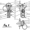
- Figur 1:
- Netzkabeldurchführung mit Netzanschlußklemmleiste in Rückansicht, Seitenansicht und Draufsicht,
- Figur 2:
- vgl. Fig. 1 ohne Draufsicht,
- Figur 3:
- Netzanschlußklemmleiste parallel zur Gehäuserückwand montiert in Vorderansicht und Draufsicht,
- Figur 4:
- Netzanschlußklemmleiste senkrecht zur Gehäuserückwand montiert in Seiten-, Unter- und Rückansicht,
- Figur 5:
- wie Figur 4 in Seiten-, Rückansicht und Draufsicht und
- Figur 6:
- wie Figur 4 in Seitenansicht, Draufsicht und Vorderansicht.
- In Figur 1 ist eine Aggregation aus zwei unterschiedlichen Installationselementen dargestellt.
- Das erste Installationselement ist eine Netzkabeldurchführung (10) mit Zugentlastung. Die Netzkabeldurchführung (10) wird bekanntlich dafür verwendet, ein in der Regel mehrpoliges Netzkabel (1) in das Innere eines elektrischen Geräts durch dessen Gerätewandung (5) zu führen und dort zu fixieren. Dazu hat es beispielsweise ein annähernd rohrförmiges Kabeldurchführteil (11), das an seinem einen Ende in eine flanschartige Einführtülle (12) übergeht und an seinem anderen Ende eine Zugentlastung (16, 17) trägt. Mit Hilfe der Einführtülle (12) liegt es an der Außenseite der Gehäusewandung (5) an. Am Kabeldurchführteil (11) sind an seiner im wesentlichen zylindrischen Außenkontur mehrere elastische Rastnasen (13) angeordnet. Die Rastnasen (13) stützen sich zur Befestigung der Netzkabeldurchführung (10) an der Innenseite der Gehäusewandung (5) ab.
- Am hinteren Bereich des Kabeldurchführteils (11) ist eine Zugentlastungsschelle (16) über ein Filmgelenk schwenkbar befestigt. An der dem Filmgelenk gegenüberliegenden Seite befindet sich in der Zugentlastungsschelle (16) eine Schellenschraube (17), mit der diese unter einem Festklemmen des Netzkabels (1) gegen das Kabeldurchführteil (11) verspannt wird.
- Unterhalb der Zugentlastungsschelle (16, 17) ist am Kabeldurchführteil (11) ein Kupplungsblock (20) angeordnet. Der Kupplungsblock (20) hat hier die Form eines Würfels. Er steht in Richtung der Mittellinie des Kabeldurchführteils (11) über dessen hinteres Ende um ca. eine halbe Kantenlänge über. Nach unten kragt der Kupplungsblock (20) gegenüber dem Kabeldurchführteil (11) um ca. eine 2/3-Kantenlänge vor.
- Am Kupplungsblock (20) sind beispielsweise zwei schwalbenschwanzförmige Kupplungselemente (24, 25) angeformt. Die Schwalbenschwänze (24, 25) sind an der Frontû (21) und Unterseite (22) des Kupplungsblocks (20) angeordnet, vgl. Figur 4. Die Längskanten der Schwalbenschwänze (24, 25) verlaufen zueinander und gegenüber der hier dargestellten Gehäusewandung (5) parallel. Die Schwalbenschwänze (24, 25) erstrecken sich über die gesamte jeweilige Seitenlänge des Kupplungsblocks (20). Gegebenenfalls können sie auch kürzer oder unterbrochen sein.
- Das zweite Installationselement ist eine Netzanschlußklemmleiste (30) mit einem mehrpoligen Klemmleistengehäuse (31). Letzteres hat drei nebeneinanderliegende, annähernd quaderförmige Kammern (38), in denen jeweils eine Kontaktelementgruppe (50) untergebracht ist.
- In Figur 1 ist pro Ansicht nur eine Kontaktelementgruppe (50) dargestellt. Sie ist innerhalb der Netzanschlußklemmleiste (30) ein Verteiler für einen Pol mit mehreren, teilweise verschiedenen Anschlußmöglichkeiten. Dazu beinhaltet die Kontaktelementgruppe (50) drei genormte Flachstecker, deren Steckfahnen (51) aus der Steckfahnenseite (32) des Klemmleistengehäuses (31) hervorstehen. Zwischen den Steckfahnen (51) verschiedener Kontaktelementgruppen liegen Trennstege (39). Ferner weist die Kontaktelementgruppe (50) einen Schraubklemmenanschluß auf, dessen Klemmschraube (53) von der Oberseite (34) des Klemmleistengehäuses (31) zugänglich ist.
- Gegenüber den Steckfahnen (51) ist ein Leiter (2) des Netzkabels (1) über eine Crimpverbindung angeschlossen. Eine hierfür notwendige Crimphülse (52) ragt aus der Crimphülsenseite (33) des Klemmleistengehäuses (31) heraus.
- Die Netzanschlußklemmleiste (30) weist an ihrer nach oben weisenden Stirnseite (36) zwei sich unter 90° kreuzende Schwalbensschwanznuten (44, 45) auf, von denen die eine parallel zur Steckfahnenseite (32) und die andere parallel zur Bodenseite (35) ausgerichtet ist. Die Schwalbenschwanznuten (44, 45) erstrecken sich hier über die gesamte Stirnseite (36). Selbstverständlich können die Schwalbenschwanznuten (44, 45) beispielsweise vor dem Erreichen der Steckfahnenseite (32) und/oder der Oberseite (34) mit oder ohne Anschlag enden. Auch ist es möglich, im Bereich der Kupplungselemente eine oder mehrere Verrastungen vorzusehen. Die Verrastungen können hierbei lösbar oder unlösbar verrasten.
- Die Schwalbenschwanznuten (44, 45) oder die Schwalbenschwänze (24, 25) können auch an der gegenüberliegenden Stirnseite oder an anderen Bereichen des Klemmleistengehäuses (31) vorhanden sein. Gegebenenfalls lassen sich über die Kupplungselemente (24, 25; 44, 45) auch zwei oder mehrere Anschlußklemmleisten miteinander kombinieren.
- Die Figuren 2 bis 6 zeigen einige Kupplungsmöglichkeiten zwischen der Netzkabeldurchführung (10) und der Netzanschlußklemmleiste (30), in denen das Netzkabel (1) und die Kontaktelementgruppe (50) nicht dargestellt sind. In den Figuren 2 und 3 ist das Klemmleistengehäuse (31) jeweils mit seiner Stirnseite (36) an der Unterseite (22) des Kupplungsblocks (20) angekuppelt.
- Bei Figur 2 steckt die Schwalbenschwanznut (45) auf dem Schwalbenschwanz (25), so daß die Bodenseite (35) des Klemmleistengehäuses (31) zur Gehäusewandung (5) zeigt.
- In Figur 3 ist das Klemmleistengehäuse (31) von unten gesehen um 90° im Gegenuhrzeigersinn gegenüber Figur 2 geschwenkt dargestellt. Der Schwalbenschwanz (25) sitzt in der Schwalbenschwanznut (44). Die Crimphülsenseite (33) des Klemmleistengehäuses (31) ist zu der Gehäusewandung (5) orientiert.
- Die Figuren 4 bis 6 zeigen Netzanschlußklemmleisten (30), die senkrecht zur Gehäusewandung (5) in das Gehäuseinnere zeigen. Die Trennfuge liegt hier parallel zur Gehäusewandung (5). Die Schwalbenschwanznuten (44, 45) umgreifen jeweils den auf der Frontseite (21) des Kupplungsblocks (20) angeformten Schwalbenschwanz (24).
- In Figuren 4 und 6 sitzt jeweils die Schwalbenschwanznut (44) auf dem Schwalbenschwanz (24). Dabei zeigt in Figur 4 die Steckfahnenseite (32) des Klemmleistengehäuses (31) nach unten und in Figur 6 nach oben.
- Bei Figur 5 ist das Klemmleistengehäuse (31) mit seiner Schwalbenschwanznut (45) so auf den Schwalbenschwanz (24) geschoben, daß die Bodenseite (35) des Klemmleistengehäuses (31) nach unten zeigt.
- Der Vollständigkeit halber sei noch angemerkt, daß die Kabeldurchführung 10 einschließlich der Einführtülle 12 zweiteilig ausgebildet sein können. Beispielsweise bestehen sie aus zwei halbkreisförmigen, insbesondere über ein Filmgelenk miteinander verbundenen Hälften, zwischen denen das Netzkabel eingelegt wird und die dann zusammengeklappt und relativ zueinander fixiert werden.
-
- 1
- Netzkabel, Kabel
- 2
- Leiter des Netzkabels
- 5
- Geräterückwand, Gehäusewandung
- 10
- Netzkabeldurchführung mit Zugentlastung
- 11
- Kabeldurchführteil
- 12
- Einführtülle, flanschartig
- 13
- Rastnasen
- 16
- Zugentlastungsschelle
- 17
- Schellenschraube
- 20
- Kupplungsblock
- 21
- Frontseite
- 22
- Unterseite
- 24, 25
- Schwalbenschwänze, Kupplungselemente
- 30
- Netzanschlußklemmleiste, mehrpolig
- 31
- Klemmleistengehäuse
- 32
- Steckfahnenseite (Vorderansicht)
- 33
- Crimphülsenseite (Rückansicht)
- 34
- Oberseite (Draufsicht)
- 35
- Bodenseite (Unteransicht)
- 36
- Stirnseite (Seitenansicht)
- 38
- Kammern
- 39
- Trennstege
- 44, 45
- Schwalbenschwanznuten, Kupplungselemente
- 50
- Kontaktelementgruppe
- 51
- Steckerfahnen
- 52
- Crimphülse
- 53
- Klemmschraube
Claims (5)
- Mehrpolige Anschlußklemmleiste zur ortsfesten Befestigung an einer Gehäusewandung eines elektrischen Geräts, insbesondere eines Haushaltsgeräts, mit Hilfe einer zugentlastenden Kabeldurchführung, wobei die Anschlußklemmleiste (30) und die Kabeldurchführung (10) als separate Teile form- und/oder kraftschlüssig über zueinander komplementäre Kupplungselemente (24, 25; 44, 45) miteinander mechanisch einer Mehrzahl von räumlichen Zuordnungen entsprechend kuppelbar sind, und
wobei ein Kupplungselementpaar (24, 25; 44, 45) aus einer an der Kabeldurchführung (10) und an der Anschlußklemmleiste (30) angeordneten Schwalbenschwanz- (24, 25) / Schwalbenschwanznut- (44, 45) / Kupplungspaarung besteht,
dadurch gekennzeichnet,
daß die Anschlußklemmleiste (30) an mindestens einer ihrer Stirnseiten (36) zwei sich kreuzende Schwalbenschwanznuten (44, 45) aufweist. - Mehrpolige Anschlußklemmleiste nach Anspruch 1,
dadurch gekennzeichnet,
daß die als Schwalbenschwanz (24, 25) ausgebildeten Kupplungselemente der Kabeldurchführung (10) unmittelbar an dieser angeformt sind. - Mehrpolige Anschlußklemmleiste nach Anspruch 1,
dadurch gekennzeichnet,
daß die als Schwalbenschwanz (24, 25) ausgebildeten Kupplungselemente der Kabeldurchführung (10) an einem lösbar an dieser angeordneten Kupplungsblock (20) angeformt sind. - Anschlußklemmleiste gemäß einem der Ansprüche 1 bis 3,
dadurch gekennzeichnet,
daß sie ein Klemmleistengehäuse (31) aufweist, in dem pro Pol eine Gruppe von Kontaktelementen (51-53) mit mehreren verschiedenen Anschlußmöglichkeiten angeordnet ist. - Anschlußklemmleiste nach einem der Ansprüche 1 bis 4,
dadurch gekennzeichnet,
daß die Kabeldurchführung (10) zweiteilig, insbesondere klappbar ausgebildet ist.
Applications Claiming Priority (2)
| Application Number | Priority Date | Filing Date | Title |
|---|---|---|---|
| DE19613748 | 1996-04-01 | ||
| DE19613748A DE19613748A1 (de) | 1996-04-01 | 1996-04-01 | Mehrpolige Anschlußklemmleiste zur ortsfesten Befestigung an einer Gehäusewandung für elektrische Geräte |
Publications (3)
| Publication Number | Publication Date |
|---|---|
| EP0800239A2 true EP0800239A2 (de) | 1997-10-08 |
| EP0800239A3 EP0800239A3 (de) | 1999-01-20 |
| EP0800239B1 EP0800239B1 (de) | 2001-09-05 |
Family
ID=7790618
Family Applications (1)
| Application Number | Title | Priority Date | Filing Date |
|---|---|---|---|
| EP97105317A Expired - Lifetime EP0800239B1 (de) | 1996-04-01 | 1997-03-28 | Mehrpolige Anschlussklemme zur ortsfesten Befestigung an einer Gehäusewandung für elektrische Geräte |
Country Status (3)
| Country | Link |
|---|---|
| EP (1) | EP0800239B1 (de) |
| AT (1) | ATE205337T1 (de) |
| DE (2) | DE19613748A1 (de) |
Family Cites Families (5)
| Publication number | Priority date | Publication date | Assignee | Title |
|---|---|---|---|---|
| FR2432779A1 (fr) * | 1978-08-02 | 1980-02-29 | Mars Actel | Reglette de raccordement |
| US4611879A (en) * | 1984-07-31 | 1986-09-16 | Dill Products Incorporated | Modular block and electrical interface assemblies employing same |
| ES282139Y (es) * | 1984-10-19 | 1985-12-16 | I.T.W. Espana, S.A. | Conector retenedor de cable |
| US4763313A (en) * | 1987-03-13 | 1988-08-09 | Partz Partnership | Plural orientation watch mount |
| DE8806765U1 (de) * | 1988-05-24 | 1988-07-14 | Electro-Terminal Ges.M.B.H., Innsbruck | Kabelanschlußvorrichtung |
-
1996
- 1996-04-01 DE DE19613748A patent/DE19613748A1/de not_active Ceased
-
1997
- 1997-03-28 DE DE59704503T patent/DE59704503D1/de not_active Expired - Fee Related
- 1997-03-28 AT AT97105317T patent/ATE205337T1/de not_active IP Right Cessation
- 1997-03-28 EP EP97105317A patent/EP0800239B1/de not_active Expired - Lifetime
Also Published As
| Publication number | Publication date |
|---|---|
| DE59704503D1 (de) | 2001-10-11 |
| EP0800239A3 (de) | 1999-01-20 |
| EP0800239B1 (de) | 2001-09-05 |
| DE19613748A1 (de) | 1997-10-02 |
| ATE205337T1 (de) | 2001-09-15 |
Similar Documents
| Publication | Publication Date | Title |
|---|---|---|
| DE3105428C2 (de) | Naßläufermotor für eine Pumpe | |
| EP0582777B1 (de) | Motoranschlussblock, insbesondere für Elektromotoren | |
| DE69211833T2 (de) | Installationseinrichtung für Netzanschluss | |
| DE112017003847T5 (de) | Leistungsverbindersystem | |
| DE2807366A1 (de) | Verbinderanordnung | |
| DE202008013757U1 (de) | Hybrid-Steckverbinder für Daten- und Powerleitungen | |
| DE102013220348A1 (de) | Relais, Relaismodul und elektrische Anschlussdose | |
| DE69710548T2 (de) | Verbinderanordnung für die Statorwicklungen eines elektrischen Motors | |
| EP1618578B1 (de) | Schaltschütz mit anschlussmodul zum ansteuern des magnetantriebes | |
| DE3447826C2 (de) | Elektro-Außenläufermotor | |
| DE60119668T2 (de) | Kabelverbinder | |
| DE112020006429B4 (de) | Kabelhalterung und Motor | |
| EP0107025B1 (de) | Am Ständerblechpaket einer elektrischen Kleinmaschine festlegbare Verbindungs-Vorrichtung und Verfahren zur Herstellung der Verbindungen | |
| DE69800453T2 (de) | Schraubklemme und Anschlussleiste für einen elektrischen Apparat | |
| DE4407083C2 (de) | Steckverbindergehäuse und zugehöriger Steckverbinder | |
| EP0813269A2 (de) | Elektrischer Verbinder | |
| DE3103455C2 (de) | Elektrischer Steckverbinder, insbesondere der Datentechnik | |
| EP0800239B1 (de) | Mehrpolige Anschlussklemme zur ortsfesten Befestigung an einer Gehäusewandung für elektrische Geräte | |
| DE102022133141B3 (de) | Anschlussdose für ein Daten- und Kommunikationsnetz | |
| EP2654183B1 (de) | Verschaltungseinrichtung für einen Elektromotor | |
| DE19737321C2 (de) | Einpolige Laststeckverbinderkombination | |
| DE3908532C2 (de) | ||
| WO1999035955A1 (de) | Staubsauger | |
| DE3538942A1 (de) | Feldstecker fuer einen elektromotor | |
| DE19508606A1 (de) | Klemmenkasten, insbesondere für elektrische Haushaltsgeräte |
Legal Events
| Date | Code | Title | Description |
|---|---|---|---|
| PUAI | Public reference made under article 153(3) epc to a published international application that has entered the european phase |
Free format text: ORIGINAL CODE: 0009012 |
|
| AK | Designated contracting states |
Kind code of ref document: A2 Designated state(s): AT DE IT |
|
| PUAL | Search report despatched |
Free format text: ORIGINAL CODE: 0009013 |
|
| AK | Designated contracting states |
Kind code of ref document: A3 Designated state(s): AT DE IT |
|
| 17P | Request for examination filed |
Effective date: 19990714 |
|
| 17Q | First examination report despatched |
Effective date: 19991008 |
|
| GRAG | Despatch of communication of intention to grant |
Free format text: ORIGINAL CODE: EPIDOS AGRA |
|
| GRAG | Despatch of communication of intention to grant |
Free format text: ORIGINAL CODE: EPIDOS AGRA |
|
| GRAH | Despatch of communication of intention to grant a patent |
Free format text: ORIGINAL CODE: EPIDOS IGRA |
|
| GRAH | Despatch of communication of intention to grant a patent |
Free format text: ORIGINAL CODE: EPIDOS IGRA |
|
| GRAH | Despatch of communication of intention to grant a patent |
Free format text: ORIGINAL CODE: EPIDOS IGRA |
|
| GRAA | (expected) grant |
Free format text: ORIGINAL CODE: 0009210 |
|
| AK | Designated contracting states |
Kind code of ref document: B1 Designated state(s): AT DE IT |
|
| PG25 | Lapsed in a contracting state [announced via postgrant information from national office to epo] |
Ref country code: IT Free format text: LAPSE BECAUSE OF FAILURE TO SUBMIT A TRANSLATION OF THE DESCRIPTION OR TO PAY THE FEE WITHIN THE PRE;WARNING: LAPSES OF ITALIAN PATENTS WITH EFFECTIVE DATE BEFORE 2007 MAY HAVE OCCURRED AT ANY TIME BEFORE 2007. THE CORRECT EFFECTIVE DATE MAY BE DIFFERENT FROM THE ONE RECORDED.SCRIBED TIME-LIMIT Effective date: 20010905 |
|
| REF | Corresponds to: |
Ref document number: 205337 Country of ref document: AT Date of ref document: 20010915 Kind code of ref document: T |
|
| REF | Corresponds to: |
Ref document number: 59704503 Country of ref document: DE Date of ref document: 20011011 |
|
| PG25 | Lapsed in a contracting state [announced via postgrant information from national office to epo] |
Ref country code: AT Free format text: LAPSE BECAUSE OF NON-PAYMENT OF DUE FEES Effective date: 20020328 |
|
| PLBE | No opposition filed within time limit |
Free format text: ORIGINAL CODE: 0009261 |
|
| STAA | Information on the status of an ep patent application or granted ep patent |
Free format text: STATUS: NO OPPOSITION FILED WITHIN TIME LIMIT |
|
| 26N | No opposition filed | ||
| PG25 | Lapsed in a contracting state [announced via postgrant information from national office to epo] |
Ref country code: DE Free format text: LAPSE BECAUSE OF NON-PAYMENT OF DUE FEES Effective date: 20021001 |