EP0800016B1 - Schaltbare, bremswirksame oder kupplungswirksame Vorrichtung, wie eine Reibungsbremse oder eine Reibungskupplung - Google Patents
Schaltbare, bremswirksame oder kupplungswirksame Vorrichtung, wie eine Reibungsbremse oder eine Reibungskupplung Download PDFInfo
- Publication number
- EP0800016B1 EP0800016B1 EP97104132A EP97104132A EP0800016B1 EP 0800016 B1 EP0800016 B1 EP 0800016B1 EP 97104132 A EP97104132 A EP 97104132A EP 97104132 A EP97104132 A EP 97104132A EP 0800016 B1 EP0800016 B1 EP 0800016B1
- Authority
- EP
- European Patent Office
- Prior art keywords
- spring
- tongue
- brake
- tongues
- clutch
- Prior art date
- Legal status (The legal status is an assumption and is not a legal conclusion. Google has not performed a legal analysis and makes no representation as to the accuracy of the status listed.)
- Expired - Lifetime
Links
Images




Classifications
-
- F—MECHANICAL ENGINEERING; LIGHTING; HEATING; WEAPONS; BLASTING
- F16—ENGINEERING ELEMENTS AND UNITS; GENERAL MEASURES FOR PRODUCING AND MAINTAINING EFFECTIVE FUNCTIONING OF MACHINES OR INSTALLATIONS; THERMAL INSULATION IN GENERAL
- F16D—COUPLINGS FOR TRANSMITTING ROTATION; CLUTCHES; BRAKES
- F16D49/00—Brakes with a braking member co-operating with the periphery of a drum, wheel-rim, or the like
-
- F—MECHANICAL ENGINEERING; LIGHTING; HEATING; WEAPONS; BLASTING
- F16—ENGINEERING ELEMENTS AND UNITS; GENERAL MEASURES FOR PRODUCING AND MAINTAINING EFFECTIVE FUNCTIONING OF MACHINES OR INSTALLATIONS; THERMAL INSULATION IN GENERAL
- F16D—COUPLINGS FOR TRANSMITTING ROTATION; CLUTCHES; BRAKES
- F16D25/00—Fluid-actuated clutches
- F16D25/06—Fluid-actuated clutches in which the fluid actuates a piston incorporated in, i.e. rotating with the clutch
- F16D25/062—Fluid-actuated clutches in which the fluid actuates a piston incorporated in, i.e. rotating with the clutch the clutch having friction surfaces
- F16D25/063—Fluid-actuated clutches in which the fluid actuates a piston incorporated in, i.e. rotating with the clutch the clutch having friction surfaces with clutch members exclusively moving axially
-
- F—MECHANICAL ENGINEERING; LIGHTING; HEATING; WEAPONS; BLASTING
- F16—ENGINEERING ELEMENTS AND UNITS; GENERAL MEASURES FOR PRODUCING AND MAINTAINING EFFECTIVE FUNCTIONING OF MACHINES OR INSTALLATIONS; THERMAL INSULATION IN GENERAL
- F16D—COUPLINGS FOR TRANSMITTING ROTATION; CLUTCHES; BRAKES
- F16D51/00—Brakes with outwardly-movable braking members co-operating with the inner surface of a drum or the like
-
- F—MECHANICAL ENGINEERING; LIGHTING; HEATING; WEAPONS; BLASTING
- F16—ENGINEERING ELEMENTS AND UNITS; GENERAL MEASURES FOR PRODUCING AND MAINTAINING EFFECTIVE FUNCTIONING OF MACHINES OR INSTALLATIONS; THERMAL INSULATION IN GENERAL
- F16D—COUPLINGS FOR TRANSMITTING ROTATION; CLUTCHES; BRAKES
- F16D59/00—Self-acting brakes, e.g. coming into operation at a predetermined speed
- F16D59/02—Self-acting brakes, e.g. coming into operation at a predetermined speed spring-loaded and adapted to be released by mechanical, fluid, or electromagnetic means
-
- F—MECHANICAL ENGINEERING; LIGHTING; HEATING; WEAPONS; BLASTING
- F16—ENGINEERING ELEMENTS AND UNITS; GENERAL MEASURES FOR PRODUCING AND MAINTAINING EFFECTIVE FUNCTIONING OF MACHINES OR INSTALLATIONS; THERMAL INSULATION IN GENERAL
- F16D—COUPLINGS FOR TRANSMITTING ROTATION; CLUTCHES; BRAKES
- F16D2121/00—Type of actuator operation force
- F16D2121/18—Electric or magnetic
- F16D2121/20—Electric or magnetic using electromagnets
- F16D2121/22—Electric or magnetic using electromagnets for releasing a normally applied brake
Definitions
- the invention is directed to a device in which a pressure ring is arranged between the first and the second device part.
- the pressure ring is connected to the first device part in a rotationally fixed or stationary manner, but by an actuating and resetting means between two to each other different axial working positions can be transferred, namely one Active position and a release position.
- At least one friction element is arranged in the device part, which is in the active position of the pressure ring is pressed together.
- Friction brake used in servomotors with which drives after a certain movement profile must be controlled precisely.
- the brake must not only be effective at a certain time, but in their Hold the rotor against the stator of the brake without play; at After the brake has come to a standstill, the applied brake must no longer rotate occur.
- the known device is as an electromagnetically ventilated spring pressure brake educated.
- the first part of the device consists of one on the machine frame fixed stator with integrated coil, on which one acts as a pressure ring Armature disk is rotatably but axially movably connected.
- the armature disk is standing under the action of compression springs that strive to move axially from the Armature disc arranged brake disc sits.
- the brake disc is the second one Part of the device acting as a rotor, which is connected to a shaft to be braked is.
- the armature disk is opened by switching on the coil current electromagnetic path against the spring force loading them from the friction element Brake disc released, which means that the brake is in the release position.
- the electromagnetic control allows only small axial movements of the Armature disk between its active and release position. Therefore, in Seen release position, the minimum air gap between which the friction element bearing brake disc on the one hand and the armature disc on the other hand very precisely be adjusted. This requires a very complex manufacture and time-consuming Assembly of components within the smallest tolerances. When worn after a long time Cumbersome readjustments are required.
- the axial Friction between the armature and brake disc is only through the Spring force determines what spring effort corresponding to high braking torques requires. In the active position of the brake, the braking torque on the armature plate drops and must be transferred axially to the stator of the brake.
- Piston-cylinder devices (US 2,284,193 A), which have a lever or a Slider act on resiliently deformable profiled disks, which between the two device parts are arranged.
- Sit on the periphery of the disks Brake shoes or clutch flanges that have friction elements with the inner surface interact in a cylindrical drum. This drum is on the brakes rotatably with the rotor and with the coupling rotatably with the driving Device part connected.
- the deformable disc has a ring shape and its ring opening is by means of the lever or slide with respect to that equipped with the friction element Ring circumference axially displaceable. With this axial displacement comes on Circumference of the ring disc creates a frictional connection with the drum.
- This device is complex and the control for deforming the brake or. clutch effective disks is cumbersome and prone to failure.
- a Application to devices between the first and second Device part have a controllable pressure ring is not visible.
- the invention has for its object an inexpensive, compact device of the type mentioned at the beginning, which is easy to assemble and fits in characterized by a particularly effective frictional engagement. According to the invention, this is achieved by the measures specified in claim 1 achieved, which have the following meaning.
- the pressure ring is torque-free.
- the spring tongues take over the spring effects and are effective via the friction element with the drum.
- the adjustment of the spring tongues on the other hand, it is taken over by the transmission links, the position of which Pressure ring is controlled.
- the transmission links are essentially dimensionally stable Components.
- the spring tongues are free of play in the area of the first device part attached and thus secure a non-rotatable connection between the two parts of the device that interact like a brake or clutch. This backlash-free attachment can be created simply by the fixed ends the spring tongues sit directly on the first part of the device.
- these fixed tongue ends can also be attached to adjacent machine components, so that they are indirectly free of play to the first part of the device.
- the radial frictional engagement in the operative position of the device should be emphasized arises at the opposite tongue ends.
- the first embodiment of the device shown in FIGS. 1 to 5 shows a friction brake 51, which acts as an electromagnetic spring-applied brake is trained.
- This brake 51 comprises a first stationary one Device part 10, which in a housing 11, for. B. an engine end shield, has a magnetic body 12, wherein in the magnetic body 12 a Coil is integrated.
- This device part 10 is the "stator" of this friction brake 51.
- a pressure ring 15 is radially at rest with the stator 10 connected, but in contrast axially movable.
- the pressure ring 15 consists of magnetizable Material and acts as an armature disk with current flow in the coil 13 the magnetic body 12 together.
- the pressure ring 15 is under the action of compression springs 16, which strive to the pressure ring 15 from the magnetic body 12 to push away in the direction of the shaft axis 22. They are in the present In case several compression springs 16 are provided in axial bores of the magnetic body 12 and the one indicated by the arrow P1 Apply axial force.
- the other device part of the brake 51 is the rotor 20, which is rotationally fixed is connected to the shaft 21 to be braked during operation.
- the Rotation of the shaft 21 is illustrated by a rotating arrow 27 in FIG. 1.
- the rotor 20 does not only comprise a rotationally fixed with the shaft 21 connected disc 23, but also a seated on the disc 23 cylindrical drum 24.
- the drum 24 carries a friction element on its inner cylinder surface 25, which in the present case consists of a on the cylinder surface 26 seated friction lining.
- a first special feature of the invention is that in the area of Stator 10 elastic body sit, which in the present case from radial resilient tongues 30 exist, hereinafter referred to briefly as "spring tongues" should be designated.
- spring tongues even made of elastic material, such as steel, which is a radial Spring force generated due to the material. But it would be too possible to provide additional springs, which are inherently inelastic Make tongues springy.
- the spring tongues 30 with its one, fixed tongue end 31 directly on the magnetic body 12 of the stator 10 anchored.
- the spring tongues 30 have the shape of Strips.
- the strip ends forming the fixed tongue end 31 are 3, in circumferential axial grooves 17 of the magnetic body 12 fixed by deformation of the axial groove after its defined Length has been set.
- the fixed end 31 of the spring tongues can have a radially angled end piece 33, which engages behind a correspondingly offset shoulder 19 on the magnetic body 12. This facilitates a defined position of the spring tongues 30 their assembly on the stator 10.
- the adjacent portion 18 of the magnetic body 12 can be offset by the adjacent length of the Spring tongue 30 projects more or less freely.
- the spring pressure brake 51 are six such spring tongues 30, on the circumference of the magnetic body 12 arranged, but of which, for the sake of simplicity of illustration 1, only the uppermost spring tongue 30 is shown in longitudinal section, while the remaining five spring tongues 30 have been omitted.
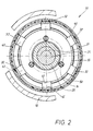
- This Distribution can be seen from the free tongue ends 32 from FIG. 2, which a cross section through the device along the section line 11-11 of Fig. 1 shows in front view.
- the invention is essentially rigid Bodies, which here consist of isolated, plate-shaped members 40. These links 40 are intended to be explained in more detail below Reasons to be referred to as "deflection members". Every spring tongue 30 is assigned a separate deflection member 40.
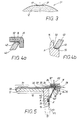
- the pressure ring 15 provided with a coaxial, front annular groove 50, one of which Groove flank and the groove base from Fig. 4b visible support surfaces 55 for the one end 41 generate.
- the deflection member 40 is in the substantially rigid and the link end 41 forms with the support surfaces 55 a first hinge point A, for which the edge at this hinge end 41 is expediently rounded. This hinge point A should follow abbreviated "inner joint".
- the other link end 42 is supported on the free tongue end 32, for which this also angled radially inward with an end piece 34 is.
- the inside of the angle 35 is supported, as can best be seen from FIG. 5 is, the link end 42, which, as shown in Fig. 4a at its Outer edge is also rounded. This creates between the Angle interior 35 and the link end 42 another hinge point B, which will be referred to as "outer joint" in the following.
- the two Link ends 41, 42 are axially and radially offset from one another, which results in an oblique course of the deflection members 40, which with the shaft axis 22 has an axial angle of approximately 60 ° in the present case Case results.
- the deflection members 40 thus take a conical shape to the shaft axis 22, the pressure ring-side link ends 41 inside and the tongue-side link ends 42 are outside.
- Fig. 1 the release position of the brake 51 1 is shown. This lies then when the coil 13 flows through its feed lines 36 is, a magnetic field builds up and thereby the pressure plate 15 due of the generated electromagnetic field to the magnetic body 12. There is then the axial starting position denoted by 15 in FIG. 5 of the pressure ring 15 before. There is then an air gap 28 between the free tongue end 32 on the one hand and the friction lining 25 on the belonging to the rotor 20 drum 24. The tongue ends 32 overlap itself with the drum 24 in the 37 described in Fig. 1 Area. The friction lining is located between the drum 24 and the tongue ends 32 enclosed radial space 47th
- the axial force P1 generated by the compression springs 16 results now a frictionally effective one, illustrated by the arrow P2 in FIG. 5 Radial force. Because of the steep location of the deflection members 40 'in this braking effective position 40 'of the deflection members also occurs, such as illustrated by the length of the two force arrows P1 and P2 in FIG. 5 is to a substantial strengthening. You get one special effective frictional engagement.
- the braking torque arises between the Spring tongues 30 and the cylinder inner surface provided with the friction lining 25 26. The resulting braking torque is from the spring tongues 30 'over said fixedly positioned tongue ends 31 directly recorded by the stator 10, which is why the pressure ring 15 is torque-free remains.
- the pressure members can 40 are already under axial and radial preload. This can be done by suitable length dimensioning of the individual deflection members Achieve 40. As a result, the mounting position of the deflection links 40 secured at their inner and outer joints A and B. To secure the position the deflection members 40 can also exist between them Serve connections.
- FIG. 6 shows, in a representation corresponding to FIG. 1, an alternative Training the friction brake, again as a spring pressure brake 52, because for transferring the pressure ring there 15 compression springs 16 also serve in the operative position.
- the axially movable Pressure ring 15 and the associated magnetic body 12 with the coil 13 are arranged at a greater radial distance from the shaft 21 than the rotor 20 provided with the cylindrical drum 24.
- the spring tongues 30, which in principle have the same structure as have in the previous embodiments, not on the outer circumference arranged of the annular magnetic body 12, but on the latter Inner periphery.
- Compression springs 16 yet another series of compression springs 16 'are used.
- Another special feature is that compared to the previous ones Embodiments of opposite inclination of the deflection members 40th
- Fig. 8 illustrates, based on the brake 53, the conditions in one scale corresponding to reality, wherever the corresponding one Air gap 28 can be seen in the ventilation position, but opposite the now effective cylinder outer surface 29. Also in this The case is the friction element in the form of a friction lining 25 in the radial space 47 between the free tongue ends 32 and the relevant cylinder outer surface 29 arranged the drum 24. There is a difference but in that this friction lining 25 is not a circumferential ring the cylinder surface 29 is fixed, but an integral part of the free Tongue ends 32; the spring tongues here carry the friction lining 25. From this Fig. 8 but something else can be seen, what in implemented in an analogous manner in the preceding exemplary embodiments is.
- the tongues at least in the Overlap area 37 with the rotor drum 24 a recognizable in Fig. 8 Have cross-sectional profile that conforms to the relevant cylinder surface 29 is formed.
- the deflection members 40 as can be seen in FIG. 8, on its tongue 32 facing Support edges 48 conform to the cylindrical profile of the free tongue ends 32 adjusted. This shape of the support edge 48 ensures surface contact and results in a low surface pressure during operation. This applies mutatis mutandis to the relationships explained in Fig. 2, and at both ends 41, 42.
- Fig. 9 shows, as a fourth embodiment of the invention Device, a clutch 54. Also here are to designate corresponding Components the same terms as in the previous embodiments the brake. For that too uses the same reference numerals, which is why, at least in analogously, the previous description applies. So it can happen that for the previously used analog parts only slightly different Terms must be used.
- the compression springs 16 strive to make the clutch 54 ineffective To hold position, namely in a decoupling position.
- the Springs 16 are supported on an axially fixed with the coupling half 10 provided support ring 49 and engage in axial bores of the pressure ring 15, which is also formed here as a pressure medium piston.
- Axially stepped sections in the device part 10 produce a cylinder part 58, which includes a pressure medium chamber 59 with the pressure ring 15.
- the pressure medium is the axial and radial pressure medium chamber 59 Channels 43 then supplied when the effective coupling position is desired is.
- the pressure medium now acts against the restoring effect of the compression springs 16 and moves the pressure ring 15 with an excess Axial force P1 to the outside.
- the axial force P1 is therefore not here spring-related, but pressure medium generated. In other respects, however the analog, from the previous embodiments conditions described.
- the device part 10 is a carrier of a group of itself substantially axially extending spring tongues 30 and between the Free tongue ends 32 and the pressure ring 15 are also supported here again a corresponding group of deflection members 40.
- the second Device part 20 has a drum 24, which here on its inner cylinder surface carries the described friction elements 25. Surrender the analog effects described in connection with FIG. 5 were.
- the clutch 54 In the operative position 30 'described in FIG. 5, where the spring tongues 30 are spread, the clutch 54 has a torque transmitted between the shafts 21, 56.
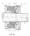
- the spring pressure brake 70 is that that from the spring tongue 30 and the associated deflection member 40th existing pair, as best seen in Fig. 11, in one piece is trained.
- This assembly is made from a strip material 60, which is elastic in the present case, i.e. z. B. consists of steel. In places where this product will be resilient , it runs in a single layer 61 while in the desired one stiff sections, several layers of the strip material are superimposed become.
- This second layer 62 can be with an end piece 63, according to FIG. 11, extend into the end region 32 of the tongue 30.
- the tape material 60 is thus made into a one-piece fold-bend product 66 which produces the pair of links 30, 40 and in the following is installed in a special way in the device.
- the leg of product 66 used to form tongue 30 becomes with its tongue end 31 in the already in the previous embodiment mentioned axial groove 17 inserted and is initially in it axially displaceable.
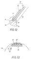
- the end 41 of the formation of the deflection member 40 serving section is, as illustrated in Fig. 12, rounded and engages in a correspondingly profiled concave groove 64 of the pressure ring 15 a.
- the pressure ring 15 with a Approach 65 provided. There it already arises in connection with the first embodiment described inner joint A. Before Installation is the angle 67 between the two legs 30, 40 of the Product 66 smaller than when installed later.
- the leg 30 of the product 66 becomes effective as defined in FIG. 11 Length 68 set.
- the tongue 30 protrudes by this length 68 the guide groove 17 out and is already in this length described radially elastically flexible manner.
- This effective tongue length 68 is fixed. This is done by e.g. B. the groove 17 compresses, whereby the spring end 31 inserted there becomes stationary.
- the installation state is the angle 67 between the two legs 30, 40 of the product 66 larger. Because the angle 67 strives to reduce in size results in the installed state a spring preload.
- Fig. 11 shows that the spring tongue 30 carrier in the present case Friction elements 25 'is.
- the friction element 25 ' is located in that end section, where also the section 63 of the second layer 62 of the strip material 60 appears.
- the end piece of the spring tongue 30 is where the friction element 25 'sits, stiffened. That is also from the cross-sectional view of 13 can be seen.
- the strip material 60 is flat, but that on the layers 61, 62 attached friction element 25 'profiled in cross-section in a special way.
- the friction element 25 ' has a different lining height in places and created a cylindrically curved friction effective surface 69 in the radial Peripheral region.
- This curvature 69 conforms to the one-dot-dash line in FIG. 13 indicated cylinder inner surface 26 of the also shown in FIG. 10 Drum 24.
- This drum 24 is seated by means of a press ring 71 rotatable on shaft 21.
- An elastic spring washer is used to arrange and guide the pressure ring 15 72, the position of which can best be seen from FIG. 11. It is located between the pressure ring 15 on the one hand and the housing of the magnetic body 12 on the other hand, which includes the electromagnetic coil 13.
- the Support compression springs 16 already mentioned in the first embodiment itself on the spring washer 72.
- the spring washer 72 is in places attached to the pressure ring 15 by bolts 73. At radially offset points for this purpose, the spring washer 72 on the magnet body housing via screws 75 12 attached.
Landscapes
- Engineering & Computer Science (AREA)
- General Engineering & Computer Science (AREA)
- Mechanical Engineering (AREA)
- Physics & Mathematics (AREA)
- Electromagnetism (AREA)
- Braking Arrangements (AREA)
- Hydraulic Clutches, Magnetic Clutches, Fluid Clutches, And Fluid Joints (AREA)
- Mechanical Operated Clutches (AREA)
Description
- Fig. 1
- einen schematischen Axialschnitt durch eine erste Ausführungsform der erfindungsgemäßen Vorrichtung, wenn diese als elektromagnetisch zu öffnende Federdruckbremse ausgebildet ist,
- Fig. 2
- einen Querschnitt durch die Vorrichtung von Fig. 1, längs der dortigen Schnittlinie II - II,
- Fig. 3
- in einer gegenüber Fig. 1 und 2 vergrößerten Darstellung einen Querschnitt durch ein Detail der in Fig. 1 gezeigten Vorrichtung, und zwar längs der Schnittlinie III-III von Fig. 1,
- Fig. 4a und 4b
- in noch weiterer Vergrößerung zwei weitere Details der in Fig. 1 gezeigten Vorrichtung,
- Fig. 5,
- in einem der Fig. 1 entsprechenden, allerdings vergrößerten Axialschnitt, ein letztes Detail der Vorrichtung in zwei unterschiedlichen Arbeitsstellungen, welche der Lüftungsstellung und der Einfallstellung der Reibungsbremse entsprechen,
- Fig. 6,
- in einer der Fig. 1 entsprechenden Darstellung, einen Axialschnitt durch ein zweites Ausführungsbeispiel der erfindungsgemäßen Vorrichtung, die zwar auch als Federdruckbremse gestaltet ist, aber durch Druckmittel geöffnet werden kann,
- Fig. 7
- zwar auch einen Axialschnitt einer dritten Ausführungsform der erfindungsgemäßen Vorrichtung, und zwar wieder als Federdruckbremse, die elektromagnetisch geöffnet werden kann, jedoch mit innenliegendem Rotor,
- Fig. 8
- einen Querschnitt durch ein Detail der in Fig. 7 gezeigten Vorrichtung, und zwar längs der Schnittlinie VIII-VIII von Fig. 7,
- Fig. 9,
- in einer der Fig. 1 entsprechenden Darstellung, einen Axialschnitt durch ein viertes Ausführungsbeispiel nach der Erfindung, wo die Vorrichtung als Kupplung ausgebildet ist, die durch Druckmittel wirksam gesetzt wird,
- Fig. 10,
- in einer der Fig. 1 entsprechenden Darstellung, einen Axialschnitt durch ein fünftes Ausführungsbeispiel nach der Erfindung, wo die aus einer Federzunge und einem Umlenkglied jeweils gebildeten Baugruppen in sich einstückig ausgebildet sind,
- Fig. 11,
- in starker Vergrößerung, ein Detail der in Fig. 10 gezeigten Vorrichtung,
- Fig. 12,
- in noch stärkerer Vergrößerung und in Analogie zu Fig. 4b, ein weiteres Detail der in Fig. 10 bzw. 11 gezeigten Vorrichtung, und
- Fig. 13,
- in einem der Fig. 8 entsprechenden Querschitt, ein Detail der in Fig. 11 gezeigten Vorrichtung, längs der Schnittlinie XIII-XIII von Fig. 11.
- 10
- erster Vorrichtungsteil, Stator bzw. erste Kupplungshälfte
- 11
- Gehäuse von 10
- 12
- Magnetkörper von 10
- 13
- elektromagnetische Spule
- 14
- Führungsbolzen für 15
- 15
- Druckring, Ankerscheibe bzw. Druckmitcelkolben
- 15'
- Arbeitsstellung von 15
- 16
- Druckfeder
- 16'
- zusätzliche Druckfeder (Fig. 7)
- 17
- Axialnut in 12 für 31
- 18
- abgesetzter Abschnitt von 12 für 30
- 19
- abgesetzte Schulter von 12 für 33
- 20
- zweiter Vorrichtungsteil, Rotor bzw. zweite Kupplungshälfte
- 21
- Welle bzw. Eingangswelle (Fig. 10)
- 22
- Wellenachse
- 23
- Scheibe von 20
- 24
- zylindrische Trommel von 20
- 25
- Reibelement, Reibbelag
- 25
- profiliertes Reibelement (Fig. 10 bis 13)
- 26
- Zylinderinnenfläche von 24
- 27
- Drehpfeil von 21
- 28
- Luftspalt
- 29
- Zylinderaußenfläche von 24
- 30
- elastischer Körper, Federzunge
- 30'
- Spreizposition von 30 (Fig. 5)
- 31
- festes Zungenende
- 32
- freies, loses Zungenende
- 32'
- Spreizstellung von 32
- 33
- festes Endstück von 31
- 34
- bewegliches Endstück von 32
- 35
- Winkelinneres bei 32
- 36
- elektrische Zuleitungen für 13
- 37
- Überlappungsbereich zwischen 32 und 24
- 38
- Druckmittel-Zylinderteil von 10 (Fig. 6)
- 39
- Druckmittelraum (Fig. 6)
- 40
- Umlenkglied
- 40'
- steile Position von 40
- 41
- erstes Gliedende von 40 bei 15
- 42
- zweites Gliedende von 40 bei 32
- 43
- Druckmittel-Kanäle (Fig. 10)
- 46
- Druckmittelkanäle (Fig. 6)
- 47
- Radialraum zwischen 32 und 24
- 48
- Stützkante von 40
- 49
- Stützring an 10 (Fig. 10)
- 50
- axiale Ringnut für 40
- 51
- Federdruckbremse (Fig. 1 bis 5)
- 52
- Federdruckbremse (Fig. 6)
- 53
- Federdruckbremse (Fig. 7)
- 54
- pneumatische Kupplung (Fig. 10)
- 55
- Stützflächen für 41
- 56
- Ausgangswelle (Fig. 10)
- 57
- Drehpfeil von 56
- 58
- Druckmittelzylinder bei 54 (Fig. 10)
- 59
- Druckmittelraum bei 54 (Fig. 10)
- 60
- Bandmaterial
- 61
- erste Lage von 60
- 62
- zweite Lage von 60
- 63
- Teilstück von 62
- 64
- konkave Nut in 15
- 65
- Ansatz von 15
- 66
- Falt-Biege-Produkt
- 67
- Winkel zwischen 30/40 (Fig. 11)
- 68
- wirksame Zungenlänge von 30 (Fig. 11)
- 69
- gewölbte Reibungs-Wirkfläche von 25' (Fig. 13)
- 70
- Federdruckbremse (Fig. 10 bis 13)
- 71
- Preßring zwischen 20, 21
- 72
- elastische Federscheibe
- 73
- Befestigungsbolzen für 72
- 74
- Ausschnitt in 15 für 73
- 75
- Schraube
- 76
- Axialbewegungs-Pfeil von 15 (Fig. 10)
- A, A'
- Innengelenk zwischen 41, 55
- B, B'
- Außengelenk zwischen 42, 35
- P1
- Axialkraft, federbedingt bzw. druck mittelbedingt (Fig. 10)
- P2
- reibungswirksame Radialkraft
- P3
- druckmittelerzeugte Gegenkraft (Fig. 6)
- x
- Strecke der Axialbewegung zwischen A, A'
- y
- Strecke der Radialbewegung zwischen B, B'
Claims (19)
- Schaltbare, bremswirksame oder kupplungswirksame Vorrichtung, wie eine Reibungsbremse (51) oder eine Reibungskupplung (54), umfassend
einen ersten Vorrichtungsteil (10), wie den Stator einer Bremse (51) oder die erste Hälfte einer Kupplung (54),
einen zweiten Vorrichtungsteil (20), wie den Rotor einer Bremse (51) oder die zweite Hälfte einer Kupplung (54),
und einen zwischen dem ersten und zweiten Vorrichtungsteil (10, 20) angeordneten Druckring (15), der zwar drehfest bzw. ruhend mit dem ersten Vorrichtungsteil (10) verbunden ist, aber durch ein Betätigungs- und Rückstellmittel, wie Federn (16), Elektromagnetismus und/oder Druckmittel, zwischen zueinander axial versetzten Arbeitsstellungen überführbar ist,
nämlich einer ersten wirksamen Stellung (Wirkstellung), wie der Einfallstellung einer Bremse (51), und einer zweiten unwirksamen Stellung (Freigabestellung), wie einer Lüftstellung der Bremse (51),
mit einer Schar von radial federnden Zungen (Federzungen 30), die mit ihrem einen, festen Zungenenden (31) im Bereich des ersten Vorrichtungsteils (10) spielfrei befestigt sind,
und mit einer Schar von Gliedern (Umlenkgliedern 40), die sich am Druckring abstützen und mit den anderen, beweglichen Zungenenden (32) verbunden sind und zur Umlenkung der Axialbewegung (x) des Druckrings (15) in eine Radialbewegung (y) der beweglichen Zungenenden (32) dienen,
wobei die beiden Gliedenden (41, 42) der Umlenkglieder (40) sowohl axial als auch radial miteinander versetzt sind,
und schließlich mit einer zylindrische Trommel (24) am zweiten Vorrichtungsteil (20), welche sich mit den beweglichen Zungenenden (32) axial überlappt (37),
wobei das Reibelement (25) im Radialraum (47) zwischen der Zylinderfläche (26; 29) der Trommel (24) und den freien Zungenenden (32) angeordnet ist. - Vorrichtung nach Anspruch 1, dadurch gekennzeichnet, daß die Umlenkglieder mit einem Gelenk (A) jeweils am Druckring (15) abgestützt sind.
- Vorrichtung nach Anspruch 1 oder 2, dadurch gekennzeichnet, daß die Umlenkglieder (40) getrennt von den Federzungen (30) hergestellt sind und mit einem weiteren Gelenk (B) an den freien Zungenenden (32) abgestützt sind.
- Vorrichtung nach Anspruch 1 oder 2, dadurch gekennzeichnet, daß die Federzunge (30) mit dem ihr zugeordneten Umlenkglied (40) einstückig ausgebildet ist.
- Vorrichtung nach Anspruch 4, dadurch gekennzeichnet, daß ein Falt-Biege-Produkt (66) aus Bandmaterial (60) ein zusammengehöriges Paar aus einem Umlenkglied (40) und einer Federzunge (30) bildet, wobei das Bandmaterial (60) wenigstens in Abschnitten des Falt-BiegeProdukts mehrlagig verläuft.
- Vorrichtung nach einem oder mehreren der Ansprüche 1 bis 5, dadurch gekennzeichnet, daß die Zungen (30) mindestens im Überlappungsbereich (37) mit der Trommel (24) ein konform zur Zylinderfläche (26; 29) ausgebildetes Querschnittsprofil aufweist.
- Vorrichtung nach einem oder mehreren der Ansprüche 1 bis 6, dadurch gekennzeichnet, daß die Federzungen (30) Träger des Reibelements (25) sind.
- Vorrichtung nach Anspruch 7, dadurch gekennzeichnet, daß die Zungen (30) zwar aus ebenem Bandmaterial (60) bestehen, aber das von Ihnen getragene Reibelement (25') profiliert ist und eine gewölbte Reibungs-Wirkfläche (69) besitzt.
- Vorrichtung nach einem oder mehreren der Ansprüche 1 bis 8, dadurch gekennzeichnet, daß die Umlenkglieder (40) untereinander verbunden sind.
- Vorrichtung nach Anspruch 9, dadurch gekennzeichnet, daß die Verbindung aus einem Halter besteht, der die Umlenkglieder (40) zueinander positioniert.
- Vorrichtung nach Anspruch 9 oder 10, dadurch gekennzeichnet, daß die Verbindung zwischen den einzelnen Umlenkgliedern (40) elastisch ausgebildet ist.
- Vorrichtung nach einem oder mehreren der Ansprüche 1 bis 11, dadurch gekennzeichnet, daß die Umlenkglieder (40) an ihrem den Zungen (30) zugekehrten Gliedende eine Stützkante (48) aufweisen, die konform zum Profil der freien Zungenenden (32) ausgebildet ist.
- Vorrichtung nach einem oder mehreren der Ansprüche 1 bis 12, dadurch gekennzeichnet, daß die Federzunge (30) einerseits und das Umlenkglied (40) andererseits unter einer axialen und radialen Vorspannung stehen, wenn das aus ihnen gebildete, zusammengehörige Paar in der Vorrichtung eingebaut ist.
- Vorrichtung nach Anspruch 13, dadurch gekennzeichnet, daß bei einem einstückig ausgebildeten Paar der Winkel (67) zwischen dem die Federzunge (30) bildenden Abschnitt des Falt-BiegeProdukts (66) einerseits und dem die Umlenkglieder (40) erzeugenden Abschnitt andererseits im Einbauzustand des Produkts (66) in der Vorrichtung größer ist als im Ausbauzustand.
- Vorrichtung nach einem oder mehreren der Ansprüche 1 bis 13, dadurch gekennzeichnet, daß bei einem zweistückigen Paar das freie Zungenende (32) radial nach innen abgewinkelt (34) ist und das zugehörige Umlenkglied (40) sich mit seinem Außenende im Winkelinneren (35) abstützt.
- Vorrichtung nach einem oder mehreren der Ansprüche 1 bis 15, dadurch gekennzeichnet, daß das eine Ende (31) der Federzunge (30) während der Montage zwar in einer Halterung (17) des Vorrichtungsteils (10) zunächst längsverschieblich ist und die Einstellung einer definierten wirksamen Länge (68) der Federzunge (30) erlaubt, aber nach der Längeneinstellung der Federzunge (30) dieses Ende (31) in der Halterung (17) der Vorrichtung ortsfest fixiert wird.
- Vorrichtung nach einem oder mehreren der Ansprüche 1 bis 15, dadurch gekennzeichnet, daß das feste Ende (31) der Federzunge (30) seinerseits radial nach innen abgewinkelt (33) ist und mit seiner Abwinkelung (33) entweder unmittelbar den ersten Vorrichtungsteil (10) hintergreift oder mittelbar dazu, an einem benachbarten Bauteil angreift.
- Vorrichtung nach einem oder mehreren der Ansprüche 1 bis 17, dadurch gekennzeichnet, daß der Druckring (15) im Vorrichtungsteil (10) durch eine biegsame Federscheibe (72) axial beweglich (76) geführt ist, wobei die Federscheibe (72) stellenweise (73) am Vorrichtungsteil (10) und an dengegenüber versetzten Stellen (75) am Druckring befestigt ist.
- Vorrichtung nach Anspruch 18, dadurch gekennzeichnet, daß bei einem als Stator (10) eines Elektromagneten ausgebildeten Vorrichtungsteils die Federscheibe (72) zwischen dem Druckring (15) einerseits und einem Gehäuse (12) des Elektromagneten andererseits angeordnet ist.
Applications Claiming Priority (2)
| Application Number | Priority Date | Filing Date | Title |
|---|---|---|---|
| DE19613763A DE19613763C1 (de) | 1996-04-06 | 1996-04-06 | Schaltbare, bremswirksame oder kupplungswirksame Vorrichtung, wie eine Reibungsbremse oder eine Reibungskupplung |
| DE19613763 | 1996-04-06 |
Publications (3)
| Publication Number | Publication Date |
|---|---|
| EP0800016A2 EP0800016A2 (de) | 1997-10-08 |
| EP0800016A3 EP0800016A3 (de) | 2000-04-12 |
| EP0800016B1 true EP0800016B1 (de) | 2002-04-24 |
Family
ID=7790630
Family Applications (1)
| Application Number | Title | Priority Date | Filing Date |
|---|---|---|---|
| EP97104132A Expired - Lifetime EP0800016B1 (de) | 1996-04-06 | 1997-03-12 | Schaltbare, bremswirksame oder kupplungswirksame Vorrichtung, wie eine Reibungsbremse oder eine Reibungskupplung |
Country Status (5)
| Country | Link |
|---|---|
| US (1) | US5873443A (de) |
| EP (1) | EP0800016B1 (de) |
| JP (1) | JP3864356B2 (de) |
| DE (2) | DE19613763C1 (de) |
| ES (1) | ES2172710T3 (de) |
Families Citing this family (14)
| Publication number | Priority date | Publication date | Assignee | Title |
|---|---|---|---|---|
| DE19850552B4 (de) * | 1998-04-17 | 2009-09-24 | GIF - Gesellschaft für Industrieforschung mbH | Betätigung für eine achsial wirksame Kupplungsdruckplatte sowie Ausrückeeinheit für eine Fahrzeugkupplung |
| DE19834093C2 (de) * | 1998-07-29 | 2000-09-07 | Brinkmann Gmbh & Co Kg | Elektromagnetisch lüftbare Federdruckbremse |
| US6336530B1 (en) * | 2000-04-07 | 2002-01-08 | Timothy L. Hottle | Vehicle brake assembly |
| DE10222101B4 (de) * | 2002-05-17 | 2015-09-10 | Chr. Mayr Gmbh + Co Kg | Elektromagnetisch gelüftete Reibungsbremse mit einer Spannzange zum gleichzeitigen Abbremsen eines Antriebsteils in Umfangs- und Axialrichtung |
| US6851526B2 (en) * | 2002-11-20 | 2005-02-08 | Deere & Company | Actuator assembly |
| DE102006024276A1 (de) * | 2006-05-24 | 2007-11-29 | Zf Friedrichshafen Ag | Elektromagnetisch betätigbare Einheit, insbesondere eine Kupplung/Bremse bzw. Sperre |
| JP5003912B2 (ja) * | 2008-09-19 | 2012-08-22 | 株式会社安川電機 | 無励磁作動型ブレーキおよびそれを用いたサーボモータ |
| MD4079C1 (ro) * | 2009-02-06 | 2011-07-31 | Сергей БУРЛАК | Dispozitiv de utilizare a energiei de frânare la autovehicule |
| DE102012004467A1 (de) * | 2012-03-08 | 2013-09-12 | Peiseler Gmbh & Co. Kg | Klemmvorrichtung und elastisches Klemmelement |
| DE102013220443A1 (de) * | 2013-10-10 | 2015-04-16 | Zf Friedrichshafen Ag | Linearstellvorrichtung mit Rückstellfeder |
| US10518761B2 (en) | 2016-07-01 | 2019-12-31 | Akebono Brake Industry Co., Ltd | Electric park brake with electromagnetic brake |
| DE102016012643B4 (de) * | 2016-10-24 | 2018-07-12 | Sew-Eurodrive Gmbh & Co Kg | Elektromagnetisch betätigbare Bremsanordnung |
| CN108061107A (zh) * | 2017-12-26 | 2018-05-22 | 无锡海核装备科技有限公司 | 被动式自动连接与解锁装置 |
| KR102127054B1 (ko) * | 2018-12-20 | 2020-06-25 | 주식회사 두산 | 전기차용 전자 브레이크 시스템 |
Family Cites Families (9)
| Publication number | Priority date | Publication date | Assignee | Title |
|---|---|---|---|---|
| US2286532A (en) * | 1940-08-02 | 1942-06-16 | Phelps M Freer | Friction coupling |
| US2284193A (en) * | 1940-08-02 | 1942-05-26 | Phelps M Freer | Friction coupling |
| US3233710A (en) * | 1963-06-25 | 1966-02-08 | Cons Electronics Ind | Electromagnetic clutch |
| DE1231496B (de) * | 1964-04-25 | 1966-12-29 | Fichtel & Sachs Ag | Temperaturabhaengig schaltende Reibungskupplung |
| DE6607298U (de) * | 1967-10-07 | 1971-02-18 | Dingler Werke Ag | Sperrvorrichtung in form einer spreizringbremse fuer hydraulisch oder pneumatisch betaetigte verstellaggregate |
| US3640363A (en) * | 1969-12-23 | 1972-02-08 | Gen Electric | Friction coupling |
| US3789965A (en) * | 1972-06-21 | 1974-02-05 | Gen Motors Corp | Vacuum clutch actuator |
| DE2814200C2 (de) * | 1978-04-03 | 1983-02-24 | Maschinenfabrik Hans Lenze Kg, 4923 Extertal | Federkraftbremse mit Elektromagnetlüftung |
| US4679745A (en) * | 1985-07-03 | 1987-07-14 | Gold Star Co., Ltd. | Reel brake device of a videocassette recorder |
-
1996
- 1996-04-06 DE DE19613763A patent/DE19613763C1/de not_active Expired - Fee Related
-
1997
- 1997-03-12 EP EP97104132A patent/EP0800016B1/de not_active Expired - Lifetime
- 1997-03-12 DE DE59707084T patent/DE59707084D1/de not_active Expired - Lifetime
- 1997-03-12 ES ES97104132T patent/ES2172710T3/es not_active Expired - Lifetime
- 1997-03-19 JP JP10507997A patent/JP3864356B2/ja not_active Expired - Fee Related
- 1997-04-04 US US08/833,025 patent/US5873443A/en not_active Expired - Fee Related
Also Published As
| Publication number | Publication date |
|---|---|
| JPH1061682A (ja) | 1998-03-06 |
| EP0800016A2 (de) | 1997-10-08 |
| US5873443A (en) | 1999-02-23 |
| ES2172710T3 (es) | 2002-10-01 |
| EP0800016A3 (de) | 2000-04-12 |
| DE19613763C1 (de) | 1997-05-07 |
| DE59707084D1 (de) | 2002-05-29 |
| JP3864356B2 (ja) | 2006-12-27 |
Similar Documents
| Publication | Publication Date | Title |
|---|---|---|
| DE202011110404U1 (de) | Bremsbetätigungsmechanismus für eine Scheibenbremse | |
| EP3488119B1 (de) | Scheibenbremse und bremsbetätigungsmechanismus | |
| DE202014002459U1 (de) | Scheibenbremse und Bremsbetätigungsmechanismus für eine Scheibenbremse | |
| EP0374268B1 (de) | Selbsttätige Nachstellvorrichtung für elektromagnetisch betätigte Kupplungs- und/oder Bremsaggregate | |
| DE19613763C1 (de) | Schaltbare, bremswirksame oder kupplungswirksame Vorrichtung, wie eine Reibungsbremse oder eine Reibungskupplung | |
| DD201935A5 (de) | Haltebremse | |
| DE202010003739U1 (de) | Scheibenbremse | |
| DE1923973A1 (de) | Scheibenbremse | |
| EP0436906A1 (de) | Betätigungsvorrichtung für eine Fahrzeugbremse, insbes. Scheibenbremse | |
| DE102006020550B4 (de) | Bremsmechanismus für eine Scheibenbremse | |
| DE102016201271A1 (de) | Bremssystem für Achse | |
| DE2836741A1 (de) | Druckmittelbetaetigte kolbenanordnung | |
| DE202010003732U1 (de) | Scheibenbremse | |
| DE2415552A1 (de) | Federbremsbetaetigungsvorrichtung | |
| WO2018215632A1 (de) | Scheibenbremse und bremsbetätigungsmechanismus | |
| DE3801911A1 (de) | Anordnung fuer eine mehrscheiben-lamellen-kupplung oder -bremse | |
| DE2840072A1 (de) | Brems- und kupplungseinrichtung | |
| DE202010003738U1 (de) | Scheibenbremse | |
| EP2093451A1 (de) | Bremskraft-Übertragungsanordnung | |
| DE102021215118B4 (de) | Bremsanordnung und Verfahren zum Betreiben einer Bremsanordnung für ein Fahrzeugrad | |
| DE102007014654A1 (de) | Bremsscheibenanordnung | |
| DE102017108744A1 (de) | Dichtungseinheit | |
| DE102011004814A1 (de) | Bremseinheit | |
| WO1990004115A1 (de) | Reibscheiben-nachstellvorrichtung | |
| DE102024120369B4 (de) | Elektromagnetisch gesteuerte Reibbremse |
Legal Events
| Date | Code | Title | Description |
|---|---|---|---|
| PUAI | Public reference made under article 153(3) epc to a published international application that has entered the european phase |
Free format text: ORIGINAL CODE: 0009012 |
|
| AK | Designated contracting states |
Kind code of ref document: A2 Designated state(s): DE ES FR GB IT |
|
| PUAL | Search report despatched |
Free format text: ORIGINAL CODE: 0009013 |
|
| AK | Designated contracting states |
Kind code of ref document: A3 Designated state(s): DE ES FR GB IT |
|
| 17P | Request for examination filed |
Effective date: 20000524 |
|
| 17Q | First examination report despatched |
Effective date: 20010117 |
|
| GRAG | Despatch of communication of intention to grant |
Free format text: ORIGINAL CODE: EPIDOS AGRA |
|
| GRAG | Despatch of communication of intention to grant |
Free format text: ORIGINAL CODE: EPIDOS AGRA |
|
| GRAH | Despatch of communication of intention to grant a patent |
Free format text: ORIGINAL CODE: EPIDOS IGRA |
|
| REG | Reference to a national code |
Ref country code: GB Ref legal event code: IF02 |
|
| GRAH | Despatch of communication of intention to grant a patent |
Free format text: ORIGINAL CODE: EPIDOS IGRA |
|
| GRAA | (expected) grant |
Free format text: ORIGINAL CODE: 0009210 |
|
| AK | Designated contracting states |
Kind code of ref document: B1 Designated state(s): DE ES FR GB IT |
|
| REG | Reference to a national code |
Ref country code: GB Ref legal event code: FG4D Free format text: NOT ENGLISH |
|
| GBT | Gb: translation of ep patent filed (gb section 77(6)(a)/1977) |
Effective date: 20020426 |
|
| REF | Corresponds to: |
Ref document number: 59707084 Country of ref document: DE Date of ref document: 20020529 |
|
| ET | Fr: translation filed | ||
| REG | Reference to a national code |
Ref country code: ES Ref legal event code: FG2A Ref document number: 2172710 Country of ref document: ES Kind code of ref document: T3 |
|
| PLBE | No opposition filed within time limit |
Free format text: ORIGINAL CODE: 0009261 |
|
| STAA | Information on the status of an ep patent application or granted ep patent |
Free format text: STATUS: NO OPPOSITION FILED WITHIN TIME LIMIT |
|
| 26N | No opposition filed |
Effective date: 20030127 |
|
| PGFP | Annual fee paid to national office [announced via postgrant information from national office to epo] |
Ref country code: ES Payment date: 20100308 Year of fee payment: 14 |
|
| PGFP | Annual fee paid to national office [announced via postgrant information from national office to epo] |
Ref country code: IT Payment date: 20100323 Year of fee payment: 14 Ref country code: FR Payment date: 20100408 Year of fee payment: 14 |
|
| PGFP | Annual fee paid to national office [announced via postgrant information from national office to epo] |
Ref country code: GB Payment date: 20100317 Year of fee payment: 14 |
|
| PGFP | Annual fee paid to national office [announced via postgrant information from national office to epo] |
Ref country code: DE Payment date: 20100308 Year of fee payment: 14 |
|
| GBPC | Gb: european patent ceased through non-payment of renewal fee |
Effective date: 20110312 |
|
| REG | Reference to a national code |
Ref country code: FR Ref legal event code: ST Effective date: 20111130 |
|
| PG25 | Lapsed in a contracting state [announced via postgrant information from national office to epo] |
Ref country code: DE Free format text: LAPSE BECAUSE OF NON-PAYMENT OF DUE FEES Effective date: 20111001 Ref country code: FR Free format text: LAPSE BECAUSE OF NON-PAYMENT OF DUE FEES Effective date: 20110331 |
|
| REG | Reference to a national code |
Ref country code: DE Ref legal event code: R119 Ref document number: 59707084 Country of ref document: DE Effective date: 20111001 |
|
| PG25 | Lapsed in a contracting state [announced via postgrant information from national office to epo] |
Ref country code: GB Free format text: LAPSE BECAUSE OF NON-PAYMENT OF DUE FEES Effective date: 20110312 Ref country code: IT Free format text: LAPSE BECAUSE OF NON-PAYMENT OF DUE FEES Effective date: 20110312 |
|
| REG | Reference to a national code |
Ref country code: ES Ref legal event code: FD2A Effective date: 20120423 |
|
| PG25 | Lapsed in a contracting state [announced via postgrant information from national office to epo] |
Ref country code: ES Free format text: LAPSE BECAUSE OF NON-PAYMENT OF DUE FEES Effective date: 20110313 |