EP0799686B1 - Verfahren zum kontinuirlichen formen von optischen anordnungen und vorrichtung dazu - Google Patents
Verfahren zum kontinuirlichen formen von optischen anordnungen und vorrichtung dazu Download PDFInfo
- Publication number
- EP0799686B1 EP0799686B1 EP96935377A EP96935377A EP0799686B1 EP 0799686 B1 EP0799686 B1 EP 0799686B1 EP 96935377 A EP96935377 A EP 96935377A EP 96935377 A EP96935377 A EP 96935377A EP 0799686 B1 EP0799686 B1 EP 0799686B1
- Authority
- EP
- European Patent Office
- Prior art keywords
- sheeting
- synthetic resin
- mold
- temperature
- embossing
- Prior art date
- Legal status (The legal status is an assumption and is not a legal conclusion. Google has not performed a legal analysis and makes no representation as to the accuracy of the status listed.)
- Expired - Lifetime
Links
Images


Classifications
-
- B—PERFORMING OPERATIONS; TRANSPORTING
- B29—WORKING OF PLASTICS; WORKING OF SUBSTANCES IN A PLASTIC STATE IN GENERAL
- B29D—PRODUCING PARTICULAR ARTICLES FROM PLASTICS OR FROM SUBSTANCES IN A PLASTIC STATE
- B29D11/00—Producing optical elements, e.g. lenses or prisms
- B29D11/00009—Production of simple or compound lenses
- B29D11/00278—Lenticular sheets
- B29D11/00288—Lenticular sheets made by a rotating cylinder
-
- B—PERFORMING OPERATIONS; TRANSPORTING
- B29—WORKING OF PLASTICS; WORKING OF SUBSTANCES IN A PLASTIC STATE IN GENERAL
- B29C—SHAPING OR JOINING OF PLASTICS; SHAPING OF MATERIAL IN A PLASTIC STATE, NOT OTHERWISE PROVIDED FOR; AFTER-TREATMENT OF THE SHAPED PRODUCTS, e.g. REPAIRING
- B29C43/00—Compression moulding, i.e. applying external pressure to flow the moulding material; Apparatus therefor
- B29C43/22—Compression moulding, i.e. applying external pressure to flow the moulding material; Apparatus therefor of articles of indefinite length
- B29C43/222—Compression moulding, i.e. applying external pressure to flow the moulding material; Apparatus therefor of articles of indefinite length characterised by the shape of the surface
-
- B—PERFORMING OPERATIONS; TRANSPORTING
- B29—WORKING OF PLASTICS; WORKING OF SUBSTANCES IN A PLASTIC STATE IN GENERAL
- B29C—SHAPING OR JOINING OF PLASTICS; SHAPING OF MATERIAL IN A PLASTIC STATE, NOT OTHERWISE PROVIDED FOR; AFTER-TREATMENT OF THE SHAPED PRODUCTS, e.g. REPAIRING
- B29C43/00—Compression moulding, i.e. applying external pressure to flow the moulding material; Apparatus therefor
- B29C43/22—Compression moulding, i.e. applying external pressure to flow the moulding material; Apparatus therefor of articles of indefinite length
- B29C43/28—Compression moulding, i.e. applying external pressure to flow the moulding material; Apparatus therefor of articles of indefinite length incorporating preformed parts or layers, e.g. compression moulding around inserts or for coating articles
-
- B—PERFORMING OPERATIONS; TRANSPORTING
- B29—WORKING OF PLASTICS; WORKING OF SUBSTANCES IN A PLASTIC STATE IN GENERAL
- B29C—SHAPING OR JOINING OF PLASTICS; SHAPING OF MATERIAL IN A PLASTIC STATE, NOT OTHERWISE PROVIDED FOR; AFTER-TREATMENT OF THE SHAPED PRODUCTS, e.g. REPAIRING
- B29C59/00—Surface shaping of articles, e.g. embossing; Apparatus therefor
- B29C59/02—Surface shaping of articles, e.g. embossing; Apparatus therefor by mechanical means, e.g. pressing
- B29C59/04—Surface shaping of articles, e.g. embossing; Apparatus therefor by mechanical means, e.g. pressing using rollers or endless belts
-
- B—PERFORMING OPERATIONS; TRANSPORTING
- B29—WORKING OF PLASTICS; WORKING OF SUBSTANCES IN A PLASTIC STATE IN GENERAL
- B29D—PRODUCING PARTICULAR ARTICLES FROM PLASTICS OR FROM SUBSTANCES IN A PLASTIC STATE
- B29D11/00—Producing optical elements, e.g. lenses or prisms
- B29D11/00605—Production of reflex reflectors
-
- B—PERFORMING OPERATIONS; TRANSPORTING
- B29—WORKING OF PLASTICS; WORKING OF SUBSTANCES IN A PLASTIC STATE IN GENERAL
- B29C—SHAPING OR JOINING OF PLASTICS; SHAPING OF MATERIAL IN A PLASTIC STATE, NOT OTHERWISE PROVIDED FOR; AFTER-TREATMENT OF THE SHAPED PRODUCTS, e.g. REPAIRING
- B29C43/00—Compression moulding, i.e. applying external pressure to flow the moulding material; Apparatus therefor
- B29C43/32—Component parts, details or accessories; Auxiliary operations
- B29C43/44—Compression means for making articles of indefinite length
- B29C43/46—Rollers
- B29C2043/461—Rollers the rollers having specific surface features
- B29C2043/463—Rollers the rollers having specific surface features corrugated, patterned or embossed surface
-
- B—PERFORMING OPERATIONS; TRANSPORTING
- B29—WORKING OF PLASTICS; WORKING OF SUBSTANCES IN A PLASTIC STATE IN GENERAL
- B29L—INDEXING SCHEME ASSOCIATED WITH SUBCLASS B29C, RELATING TO PARTICULAR ARTICLES
- B29L2011/00—Optical elements, e.g. lenses, prisms
- B29L2011/0016—Lenses
Definitions
- This invention relates to a method for continuously forming an array of optical elements such as cube-corner prisms, linear prisms, lenticular lenses, refractive lenses, Fresnel lenses, linear Fresnel lenses or hologram patterns, on sheeting such as synthetic resin sheeting, and apparatus therefor. More particularly, it relates to a method for continuously forming an array of cube-corner type microprisms which is useful in the production of cube-corner type retroreflectors (i.e., articles reflecting most of the incident light back toward the light source), and apparatus therefor.
- cube-corner type microprisms which is useful in the production of cube-corner type retroreflectors (i.e., articles reflecting most of the incident light back toward the light source), and apparatus therefor.
- retroreflective sheeting is produced by depositing a curable molding material upon a cube-corner mold and applying a transparent, flexible film material over the molding material, after which the molding material is cured and bonded to the film material.
- the resins specifically described in this patent for use as molding materials are substantially limited to crosslinkable resins such as plastisol type vinyl chloride resin containing a crosslinking acrylic ester monomer.
- crosslinkable resins such as plastisol type vinyl chloride resin containing a crosslinking acrylic ester monomer.
- the embossing temperature is limited to a temperature higher than the glass transition temperature of the synthetic resin and lower than the glass transition temperature of a carrier film. Consequently, the resin tends to have insufficient fluidity, and hence requires a long pressing time or a plurality of pressure points. Thus, these methods are not considered to be highly productive. Moreover, these methods have the disadvantage that the elements embossed under such temperature conditions show a reduction in shape accuracy owing to elastic deformation.
- the embossing temperature is limited to a temperature higher than the glass transition temperature of the synthetic resin and lower than the glass transition temperature of a carrier film as described above, the choice of a carrier film is disadvantageously limited when high-melting synthetic resin sheeting made, for example, of a polycarbonate resin is to be embossed.
- Japanese Patent Laid-Open Nos. 159039/'81 and 159127/'81 there is disclosed a method in which synthetic resin sheeting is fed between a pair of endless belts and an array of optical elements such as lenticular lenses or Fresnel lenses is formed on one surface of the synthetic resin sheeting.
- these patents give no specific description of the melt viscosity conditions, heating conditions and cooling conditions which can be employed for the embossing of the synthetic resin.
- the apparatus disclosed therein does not have a construction which enables the embossed synthetic resin to be stripped after sufficient cooling, and is not suitable for the formation of an array of optical elements having satisfactorily high optical accuracy.
- the problems associated with the formation of an array of optical elements include insufficient filling into the mold due to poor fluidity of the synthetic resin, elastic deformation after pressure release due to insufficient melting, shrinkage due to chemical linkages of the synthetic resin and/or evaporation of the solvent and low-molecular components in the synthetic resin, and the like.
- Pricone et al. have employed a method in which a plurality of pressure points are provided or a method in which the traveling speed of the synthetic resin sheeting is reduced to provide a sufficient pressing time.
- neither of these methods is considered to be highly productive.
- undesirable misalignment of the pattern may result because the synthetic resin sheeting separated from the mold is pressure-formed again at the next pressure point.
- a method in which a synthetic resin melted, for example, in an extruder is fed in the form of sheeting is also described therein.
- no specific description is given of the temperature conditions and synthetic resin melting conditions which can be employed to form a highly accurate array of optical elements.
- Deformation of the optical elements due to shrinkage of the synthetic resin is a phenomenon in which, during pressure forming or after pressure release, the optical element-bearing surface required to be essentially planar shrinks and deforms into a concave surface owing to chemical linkages, evaporation of the solvent and low-molecular components in the synthetic resin, and the like.
- This shrinking phenomenon tends to prevent the synthetic resin from being stripped from the mold and thereby cause a reduction in productivity.
- these low-molecular components tend to adhere to the surface of the mold and cause such troubles as poor strippability and a reduction in surface smoothness.
- any volatile components remaining in the resulting embossed sheeting cause an additional trouble in that they gradually evaporate during use of the product to deform the optical elements and thereby detract from the performance of the product.
- the present inventors have made investigations with a view to solving the above-described problems encountered when an array of optical elements is continuously formed on synthetic resin sheeting and, in particular, when an array of cube-corner type microprisms for use in the production of cube-corner type retroreflectors is continuously formed thereon.
- the present invention provides a method for continuously forming an array of optical elements which comprises feeding synthetic resin sheeting continuously, pressing said sheeting against a moving mold having a pattern for defining an array of optical elements in a thermoforming zone to bring said sheeting into intimate contact with said mold and thereby form an array of optical elements on one surface of said sheeting, feeding a carrier film to the side of said sheeting opposite to said mold and bringing it into close contact with said sheeting, moving said sheeting in engagement with said mold into a cooling zone where said sheeting is cooled to a temperature lower than the glass transition temperature of the synthetic resin, and stripping said sheeting from said mold, characterized in that
- the present invention also provides an apparatus for continuously forming an array of optical elements which comprises seamless embossing means provided on its outer surface with a mold having a pattern for defining an array of optical elements; heating means for heating said embossing means and thereby causing said embossing means to define a thermoforming zone; synthetic resin sheeting feed means for continuously feeding synthetic resin sheeting to the thermoforming zone of said embossing means and including heating means for raising the temperature of the fed sheeting to a temperature in the flow temperature region of the synthetic resin and hence for feeding the synthetic resin sheeting having a flow temperature continuously and directly to the thermoforming zone of said embossing means; pressure forming means for pressing the fed synthetic resin sheeting against the mold provided on the outer surface of said embossing means and having a pattern for defining an array of optical elements in the thermoforming zone of said embossing means to bring the sheeting into intimate contact with the mold and thereby form an array of optical elements on one surface of the sheeting; drive means connected to said embossing means
- Shape of optical elements and method of making a master mold for an array of optical elements are shapes of optical elements and method of making a master mold for an array of optical elements :
- cube-corner type microprisms which are useful in the production of cubecorner type retroreflectors (i.e., articles reflecting most of the incident light back toward the light source) are preferred.
- a master mold for an array of optical elements i.e., a basic mold required to form such an array of optical elements continuously on synthetic resin sheeting
- various methods are known. They include, for example, a method in which optical elements are formed on a metallic surface by cutting grooves in a plurality of directions by such means as fly cutting, ruling or diamond turning [see, for example, Japanese Patent Laid-Open No. 100103/'85 (corresponding to U.S Pat. No.
- a master mold for an array of cube-corner type microprisms suitable for use in the present invention can be made according to-the method disclosed in PCT International Application No. PCT/JP96/02117 filed on July 26, 1996. Specifically, this method comprises stacking a plurality of flat sheets having two mutually parallel major surfaces, cutting one side face of the resulting sheet stack so as to make V-shaped grooves in a direction perpendicular to the major surfaces and at a fixed pitch and thereby form a series of continuous roof-shaped projections having a vertical angle of about 90°, and shifting the sheets so that the vertices of the roof-shaped projections formed on each sheet meet the bottoms of the V-shaped grooves formed on an adjacent sheet, and is characterized in that the sheets used therefor have a thickness of 50 to 500 ⁇ m and the sheets are formed of a synthetic resin having a Rockwell hardness of not less than 70.
- the type of the synthetic resin used for the synthetic resin sheeting on which an array of optical elements is formed according to the present invention so long as the resin has high transparency.
- Specific examples thereof include acrylic resins, polyester resins, polycarbonate resins, vinyl chloride resin, polystyrene resin, polyurethane resins and polyolefin resins.
- acrylic resins, polycarbonate resins, vinyl chloride resin and polyurethane resins are preferred from the viewpoint of weather resistance, transparency and the like.
- a multiplicity of reversed molds usable in the forming of synthetic resin sheeting can be reproduced according to a per se known technique such as electroforming [see, for example, "Special Electroforming and Its Application -- Materials and Chemicals Used for Electroforming", Manabu Inoue. Practical Surface Techniques, 35 (8), 10-16(1988)]. Moreover, these molds reproduced by electroforming can be joined together to make a large-sized mold.
- both ends thereof can be joined, for example, by laser welding to form a seamless belt-like mold (or an embossing belt) for embossing synthetic resin sheeting to form an array of optical elements on a surface thereof.
- a seamless belt-like mold can be made by i mounting a plurality of molds reproduced by electroforming as described above, on the inside surface of a rotary drum type electrode without leaving any space between the molds, and performing further electroforming.
- the thickness of the belt-like mold it is usually preferable that its thickness is in the range of 1/3,000 to 1/500, more preferably 1/1,200 to 1/800, of the diameter of the rolls used.
- embossing means of the embossing roll type in which a mold for an array of optical elements is directly mounted on the surface of a roll.
- this embossing means of the embossing roll type is preferred because a pattern of elements can be directly cut in the surface of the roll.
- the screw of the extruder may have a diameter/length ratio of 1/20 to 1/35, a compression ratio of 1.5 to 2.0, and a rotational speed of about 20 to 100 rpm.
- a vacuum vent, a gear pump feeder and the like may be used in combination.
- Usable calender rolls are ones having a diameter of about 100 to 500 mm.
- Metal rolls having a specular surface are preferred, and it is more preferable that they have a structure capable of internal heating. It is also desirable to control the clearance between the calender rolls so that the desired thickness of the synthetic resin sheeting will be obtained.
- an example of the method of feeding previously formed synthetic resin sheeting to the thermoforming zone after heating the sheeting to a temperature in or above its flow temperature region is one in which the formed synthetic resin sheeting is heated to a temperature in or above its flow temperature region by passing it between two or more heating rolls.
- indirect heating devices such as a hot blast heater, a near-infrared lamp heater and a farinfrared lamp heaters may be used in combination.
- Thermoforming zone and heating means are identical to Thermoforming zone and heating means :
- the synthetic resin sheeting having a temperature in its flow temperature region which has been fed directly to the thermoforming zone of the apparatus for continuously forming an array of optical elements by the above-described method and means of feeding the synthetic resin sheeting, is pressed against the mold having a pattern for defining an array of optical elements by pressure forming means and brought into intimate contact with the mold. Then, the synthetic resin sheeting continues to travel through the thermoforming zone while remaining in engagement with the mold, so that an array of optical elements is formed on one surface of the sheeting.
- the pressure forming means may comprise, for example, at least one pressure roll disposed so as to be opposite to the above-described embossing belt or embossing roll.
- a roll made of metal, rubber or synthetic resin can be used as the pressure roll, and the pressure applied during pressing is not strictly limited because it depends on the type of the synthetic resin constituting the sheeting, the shape of the mold, and the like. However, it is usually preferable that the pressure is in the range of 5 to 100 kg/cm, more preferably about 20 to 60 kg/cm, with respect to the width of the roll.
- the speed of continuous pressure forming may generally be in the range of 5 to 30 m/min and preferably 7 to 15 m/min.
- a plurality of rolls can be used according to the size of the optical elements, the pressure and speed of forming, and the like.
- the heating means there can be used an internal heating method in which heat is supplied from the inside of the roll.
- the heat supply means may comprise one of the dielectric heating type, the heat transfer medium circulation type or the like.
- indirect heating devices such as a hot blast heater, a near-infrared lamp heater and a farinfrared lamp heater can also be used in combination.
- the thermoforming zone can be formed by using a heating roll as one of the rolls on which the belt is mounted.
- this can be accomplished by defining a heating zone in half of the roll.
- the belt may be preheated by an auxiliary heating means as required.
- flow temperature region means a temperature region in which synthetic resin sheeting becomes molten and, when pressed against a mold having a pattern for defining an array of optical elements, can flow in conformity with the shape of the mold and thereby fill and engage the mold.
- this flow temperature region makes it possible to overcome the previously described disadvantages which have frequently been encountered in the prior art, such as insufficient filling into the mold due to poor fluidity of the synthetic resin, and elastic deformation after pressure release due to insufficient melting.
- the flow temperature region ranges from the temperature at which the synthetic resin has a melt viscosity of not greater than 100,000 poises and preferably not greater than 50,000 poises, to less than the decomposition temperature of the synthetic resin.
- the melt viscosity of the synthetic resin can be measured according to a temperature-rise test using a Koka type flow tester as described in JIS K-7210, and the flow temperature region can be determined from the temperature-viscosity relationship thus obtained.
- a 1.5 g sample of the synthetic resin is placed in a metallic cylinder having a crosssectional area of 1 cm 2 and fitted with a die having an orifice diameter of 1.0 mm and a length of 10 mm and adjusted to a starting temperature of 140°C, and extruded under an applied force of 30 kgf while being heated at a rate of temperature rise of 3°C/min. Then, the melt viscosity of the synthetic resin can be determined from the relationship between the temperature of the sample and the extrusion rate so measured.
- the temperature of the synthetic resin sheeting located in the thermoforming zone can be measured, for example, with an infrared thermometer.
- a surfacing film can be laminated to the surface of the sheeting opposite to the mold (hereinafter also referred to as the outer surface) as required, in order to improve its properties such as weather resistance, solvent resistance, stain resistance, cleaning resistance, flexibility, cold resistance, mar resistance, abrasion resistance and flexing resistance.
- the means of lamination may comprise, for example, a rubber roll disposed so as to be opposite to the embossing belt.
- the surfacing film is guided by rubber rolls, fed to the synthetic resin sheeting having a temperature at least equal to or higher than the flow starting temperature and preferably in the flow temperature region, and laminated thereto by thermocompression bonding with a rubber roll.
- the surfacing film is preferably laminated by heat fusion bonding at a temperature equal to or higher than its glass transition temperature.
- flow starting temperature means the temperature at which, when a resin that is solid at ordinary temperatures is heated beyond its glass transition temperature, it softens and then begins to flow to such an extent as to permit pressure forming. More specifically, it means the temperature at which the synthetic resin has a melt viscosity of not greater than 1,000,000 poises.
- the materials which can be used for the surfacing film laminated to the outer surface of the synthetic resin sheeting for the above-described purpose include, for example, acrylic resins, fluorine containing resins, vinyl chloride resin, polyester resins and polyurethane resins.
- acrylic resins fluorine containing resins
- vinyl chloride resin vinyl chloride resin
- polyester resins polyurethane resins.
- the thickness of the surfacing film it may generally be in the range of 10 to 100 ⁇ m and preferably about 20 to 50 ⁇ m.
- the surfacing film can be printed with logos, traffic signs or the like.
- the printing is preferably made on the back side of the surfacing film (i.e., that side of the surfacing film which comes into contact with the synthetic resin sheeting) so that the printing ink may not be removed.
- a carrier film is fed and laminated to the side of the sheeting opposite to the mold, immediately before the sheeting in engagement with the mold passes into the cooling zone.
- the means of laminating the carrier film may comprise, for example, a roll (e.g., rubber roll) disposed so as to be opposite to the embossing belt.
- the carrier film is guided by rubber rolls, fed to the outer surface of the synthetic resin sheeting having a temperature at least equal to or higher than the flow starting temperature, or the surface of the optionally laminated surfacing film opposite to the sheeting, and laminated thereto by thermocompression bonding with a roll.
- the carrier film when the carrier film is pressed against and laminated to the outer surface of the synthetic resin sheeting which has been melted, brought into intimate contact with the mold and thereby engaged the mold, or the surface of the optionally laminated surfacing film opposite to the synthetic resin sheeting, the mating surface of the carrier film is transcribed to the outer surface of the synthetic resin sheeting or the outer surface of the surfacing film, so that a smooth surface can be produced.
- the carrier film also functions as a protective layer serving, for example, to protect the product surface from being marred during manufacture. Since cooling is started immediately after the carrier film is laminated to the synthetic resin sheeting or the surfacing film, it is possible to use a synthetic resin film having a flow temperature almost equal to that of the synthetic resin sheeting or the surfacing film.
- the synthetic resin which can be used for the carrier film include resins having relatively high thermal resistance, such as polyethylene terephthalate resin, polyimide resins and aramid resins.
- synthetic resins having a glass transition temperature almost equal to that of the synthetic resin used for the synthetic resin sheeting can also be used.
- the thickness of the carrier film may generally be in the range of 35 to 150 ⁇ m and preferably about 50 to 100 ⁇ m.
- Cooling zone and cooling means are Cooling zone and cooling means:
- thermocompression bonding of the carrier film Since the temperature used for thermocompression bonding of the carrier film is almost equal to the temperature at which the synthetic resin sheeting is pressed against the mold so as to come into intimate contact with the mold and thereby engage the mold, it is necessary to establish a cooling zone for rapidly cooling the laminate immediately after its lamination so that the carrier film may not be melted.
- the cooling means used in the cooling zone may comprise, for example, a method in which cooling medium blowing nozzles for blowing a cooling medium (e.g., air, nitrogen gas or water) upon one surface or both surfaces of the belt-like mold (or embossing belt) are.disposed at positions downstream of the carrier film laminating means; a method in which one of the two rolls having the embossing belt mounted thereon is designed as a heating roll (or thermorforming zone) as described above and the other is designed as a cooling roll which is cooled with a medium such as water; or a combination of these two methods.
- the cooling zone is defined by the cooling roll and the region of the embossing belt in which the cooling medium blowing nozzles are disposed.
- a forming means comprising a roll provided on its surface with a pattern for defining an array of optical elements (e.g., the above-described embossing roll)
- the cooling zone in half of the roll.
- the two temperature zones i.e., the thermoforming zone and the cooling zone
- the two temperature zones can be established on the roll by dividing a plurality of passages formed in the roll into two groups with the aid of two manifolds and passing heating and cooling media through the respective manifolds.
- the laminate of the synthetic resin sheeting and the carrier film, or the laminate of the synthetic resin sheeting. the surfacing film and the carrier film is cooled to a temperature lower than the glass transition temperature (Tg) of the synthetic resin, preferably lower than [Tg(°C) - 20°C], and more preferably lower than [Tg(°C) - 50°C].
- Tg glass transition temperature
- the cooled laminate of the synthetic resin sheeting and the carrier film or the cooled laminate of the synthetic resin sheeting, the surfacing film and the carrier film (which may hereinafter be referred to briefly as the sheet laminate) can be stripped from the mold by a common means such as a stripping roll.
- the stripping roll is preferably disposed so as not to be in contact with the cooling roll, so that the cooled sheet laminate to be stripped from the mold may not be pressed against the cooling roll by the stripping roll.
- the stripping roll there can be used, for example, a rubber roll, a metal roll or a synthetic resin roll.
- the synthetic resin optical sheeting having an array of optical elements formed thereon in the above-described manner is used as a product after the carrier film is stripped.
- back sheeting may be disposed to create a capsular structure for the purpose of securing a layer of air on the surface of the optical sheeting on which the array of optical elements is formed. This can be accomplished, for example, by heat-embossing the back sheeting from the back side thereof (i.e., the side opposite to the optical sheeting) to form a reticulated connecting wall having the shape of intersected continuous thin lines and thereby bonding the back sheeting partly to the surface of the optical sheeting on which the array of optical elements is formed.
- a light-reflecting mirror layer may be formed on the surface of the array of optical elements of the optical sheeting by metal vapor deposition, chemical silver plating or other technique, and/or an adhesive layer or the like may be applied to the back side of the back sheeting or to the mirror layer formed on the surface of the array of optical elements for the purpose of joining the product to other structures.
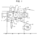
- a circular seamless embossing belt 3 is mounted on two steel rolls 1 and 2.
- Roll 1 is a thermoforming roll having therein a heating means of the oil circulation type and thereby defining a thermoforming zone.
- Roll 2 is a cooling roll having therein a cooling means for cooling by use of a cooling medium and thereby defining the main part of a cooling zone.
- seamless embossing belt 3 is provided on its surface with a mold having a pattern for defining an array of optical elements.
- Synthetic resin sheeting 5 is continuously extruded through an extrusion die 4 attached to an extruder while being maintained at a temperature in its flow temperature region, and fed to a gap between a pressure-forming rubber roll 7 biased by means of an oil-hydraulic cylinder 6, and the surface of embossing belt 3 on roll 1 located in the thermoforming zone.
- synthetic resin sheeting 5 is pressed against the mold provided on the surface of the embossing belt and having a pattern for defining an array of optical elements, and brought into intimate contact therewith, so that sheeting 5 engages the mold and, at the same time, an array of optical elements is formed on one surface of sheeting 5.
- Synthetic resin sheeting 5 which is now in engagement with the mold, travels through the thermoforming zone together with embossing belt 3.
- carrier sheeting 9 is fed to the outer surface of sheeting 5 and compressed with a laminating pressure roll 8 made of rubber.
- carrier sheeting 9 is laminated to synthetic resin sheeting 5 and, at the same time, the formation of an array of optical elements is completed.
- Roll 8 is biased by means of an air cylinder 11 through the medium of a metallic arm 10 rotatably supported at a supporting point, and carrier sheeting 9 is wound off by an unwinder 12.
- the cooled sheet laminate is stripped from the endless belt by means of a stripping roll 14 and wound up as a product.
- an endless belt 27 is mounted on two steel rolls 25 and 26.
- Roll 25 is a thermoforming roll having therein a heating means of the dielectric heating type and thereby defining a thermoforming zone.
- Roll 26 is a cooling roll having therein a cooling means for cooling by use of a cooling medium and thereby defining the main part of a cooling zone.
- seamless embossing belt 27 is provided on its surface with a mold having a pattern for defining an array of optical elements.
- Synthetic resin sheeting is continuously extruded through an extrusion die 21 attached to an extruder while being maintained at a temperature in its flow temperature region, and fed to a gap between a pair of steel calender rolls 23 and 24 biased by means of an oil-hydraulic cylinder 22. Then, the synthetic resin sheeting travels around calender roll 23 and is pressed by calender roll 23 against embossing belt 27 located in the thermoforming zone. Thus, the synthetic resin sheeting is brought into intimate contact with the mold provided on the surface of the embossing belt and having a pattern for defining an array of optical elements, so that the sheeting engages the mold and, at the same time, an array of optical elements is formed on one surface of the sheeting. In this step, intimate contact may be completed by disposing a pressure roll adjacent to calender roll 23, if desired.
- thermoforming zone a surfacing film 29 is fed to the outer surface of the sheeting and compressed with a laminating pressure roll 28 made of rubber, so that surfacing film 29 is laminated to the synthetic resin sheeting.
- Roll 28 is biased by means of an air cylinder 31 through the medium of a metallic arm 30, and surfacing film 29 is wound off by an unwinder 32.
- carrier sheeting 34 is fed to the outer surface of the laminated surface film and compressed with a laminating pressure roll 33 made of rubber.
- carrier sheeting 34 is laminated to the surface of the surfacing film opposite to the synthetic resin sheeting and, at the same time, the formation of an array of optical elements is completed.
- Roll 33 is biased by means of an air cylinder 36 through the medium of a metallic arm 35, and carrier sheeting 34 is wound off by an unwinder 37.
- the sheet laminate composed of the synthetic resin sheeting, surfacing film 29 and carrier sheeting 34 then passes into the cooling zone where it is cooled with an air blast cooler 38 and further cooled to a temperature lower than the glass transition temperature of the synthetic resin on roll 26 constituting the main part of the cooling zone.
- the cooled sheet laminate is stripped from endless belt 27 by means of a stripping roll 39 and wound up as a product by a winder 40. Endless belt 27, from which the sheet laminate has been stripped, travels along a preheater 41 of the near-infrared heating type for preheating it to the pressing temperature, and then returns to a gap between rolls 25 and 23.
- an embossing roll 55 has a structure in which heat exchange can be effected by passing a heat transfer medium through its internal passages 56, and is divided into two sections by manifolds 57 and 58 mounted on the peripheral part of the roll.
- a heated heat transfer oil is passed through the passages in the upper part of roll 55 by way of heating manifold 57 to define a thermoforming zone, while cooling water is passed through the passages in the lower part of roll 55 by way of cooling manifold 58 to define a cooling zone.
- embossing roll 55 is divided into the two temperature zones.
- embossing roll 55 is provided on its surface with a mold having a pattern for defining an array of optical elements.
- Synthetic resin sheet 52 is continuously extruded through an extrusion die 51 attached to an extruder while being maintained in its flow temperature region, and fed to a gap between a pair of steel calender rolls 53 and 54 and compressed thereby. Then, synthetic resin sheeting 52 travels around calender roll 54 and is pressed by calender roll 54 against the thermoforming zone of embossing roll 55. Thus, synthetic resin sheeting 52 is brought into intimate contact with the mold provided on the surface of embossing roll 55 and having a pattern for defining an array of optical elements, so that the sheeting engages the mold and, at the same time, an array of optical elements are formed on one surface of the sheeting.
- Synthetic resin sheeting 52 which is now in engagement with the mold, travels with the rotation of embossing roll 55.
- carrier sheeting 60 is fed to the outer surface of sheeting 52 and compressed with a laminating roll 59.
- carrier sheeting 60 is laminated to sheeting 52 and, at the same time, the formation of an array of optical elements is completed.
- the resulting laminate of synthetic resin sheeting 52 and carrier sheeting 60 then passes into the cooling zone of embossing roll 55 where it is rapidly cooled.
- the surface of the laminate is also cooled with an air blast cooler 61.
- the laminate is cooled to a temperature lower than the glass transition temperature of the synthetic resin.
- the cooled sheet laminate is stripped by means of a stripping roll 62 and wound up as a product.
- optical elements are formed by pressure forming in the flow temperature region of the synthetic resin. Accordingly, the disadvantages which have frequently been encountered in the prior art, such as insufficient filling into the mold due to poor fluidity of the resin, elastic deformation after pressure release due to insufficient melting, and shrinkage due to chemical linkages of the resin and/or evaporation of the solvent, can be overcome, so that an array of optical elements having a very high degree of optical accuracy can be formed.
- the apparatus of the present invention makes it possible to achieve the quick filling of synthetic resin sheeting into a mold and thereby improve the productivity of an array of optical elements markedly.
- the present invention is further illustrated by the following example.
- an endless belt 27 having a perimeter of 4,000 mm and a width of 700 mm was mounted on a pair of steel rolls 25 and 26 having a diameter of 300 mm and a width of 800 mm.
- Upper roll 25 could be heated to 280°C with a dielectric heating means disposed therein.
- lower roll 26 had a cooling means therein for cooling with water so as to give a surface temperature of 30°C.
- Seamless embossing belt 27 was mounted on this pair of rolls, and the belt was provided on its surface with a pattern of cube-corner retroreflective elements having a prism height of 100 ⁇ m and an optical axis tilt angle of 8° and comprising trigonal prism cavities arranged in a closest packed state over a width of 600 mm.
- a polycarbonate resin (manufactured by Mitsubishi Engineering Plastics Co., Ltd.) was extruded at a temperature of 280°C through a 650 mm wide coat-hanger type extrusion die 21 attached to a single-screw extruder having a diameter of 50 mm.
- the resulting 250 ⁇ m thick polycarbonate resin sheeting was passed between a pair of chrome-plated rolls 23 and 24 having a surface temperature of 180°C and biased by means of an oil-hydraulic cylinder 22, and then fed to the above-described belt apparatus where the sheeting was brought into intimate contact with the embossing belt of the belt apparatus under an applied linear pressure of 50 kg/cm.
- the polycarbonate resin sheeting traveling together with the belt was pressed again under an applied pressure of 30 kg/cm by means of a silicone roll (not shown) having a diameter of 200 mm and a width of 700 mm.
- a 30 ⁇ m thick acrylic resin film (manufactured by Mitsubishi Rayon Co., Ltd.) 29 was laminated to the polycarbonate resin sheeting by means of a silicone roll 28 having a diameter of 200 mm and a width of 700 mm. While this polycarbonate resin sheeting 29 having the acrylic resin film fusion-bonded thereto was advancing together with the embossing belt, 75 ⁇ m thick polyethylene terephthalate resin sheeting 34 was further laminated to the overlying acrylic resin film by means of a silicone roll 33 having a diameter of 200 mm and a width of 700 mm.
Landscapes
- Engineering & Computer Science (AREA)
- Mechanical Engineering (AREA)
- Health & Medical Sciences (AREA)
- Manufacturing & Machinery (AREA)
- Ophthalmology & Optometry (AREA)
- Shaping Of Tube Ends By Bending Or Straightening (AREA)
- Casting Or Compression Moulding Of Plastics Or The Like (AREA)
- Blow-Moulding Or Thermoforming Of Plastics Or The Like (AREA)
Claims (12)
- Verfahren zum kontinuierlichen Ausformen eines Feldes von optischen Elementen, welches Verfahren die folgenden Schritte umfasst:dadurch gekennzeichnet, dassDas kontinuierliche Zuführen von einem Blattmaterial aus Kunstharz,das Pressen dieses Blattmaterials gegen eine sich bewegende Form mit einem Muster zum Definieren eines Feldes von optischen Elementen in einer Thermoformzone, um das Blattmaterial in engen Kontakt mit der Form zu bringen und so ein Feld von optischen Elementen auf einer Oberfläche des Blattmaterials auszuformen,das Zuführen einer Trägerfolie zu der der Form gegenüberliegenden Seite des Blattmaterials und das enge Inkontakbringen der Trägerfolie mit dem Blattmaterial,das Bewegen des Blat-tmaterials in Eingriff mit der Form in eine Kühlzone, wo das Blattmaterial auf eine Temperatur unterhalb der Glasübergangstemperatur des Kunstharzes abgekühlt wird, undAbziehen des Blattmaterials von der Form,(a) das Blattmaterial aus Kunstharz mit einer Flusstemperatur zuerst zu der Thermoformzone geführt wird,(b) in der Thermoformzone die Temperatur des Blattmaterials aus Kunstharz in dem Flusstemperaturbereich des Kunstharzes gehalten wird; und(c) die Trägerfolie dem Blattmaterial zugeführt wird, nachdem das Blattmaterial aus Kunstharz die Thermoformzone passiert hat, wo es in engen Kontakt mit der Form gebracht worden ist.
- Verfahren nach Anspruch 1, wobei, nachdem das Blattmaterial aus Kunstharz in engen Kontakt mit der Form gebracht worden ist, und während das Kunstharz eine Temperatur hat, die zumindest gleich oder höher als seine Fluss-Starttemperatur ist, der der Form gegenüberliegenden Seite des Blattmaterials in der Thermoformzone eine bedeckende Folie zugeführt und darauf laminiert wird, und dass die Trägerfolie dann der der Form gegenüberliegenden Seite des entstehenden Laminats zugeführt wird.
- Verfahren nach Anspruch 1, wobei der Flusstemperaturbereich des Kunstharzes von der Temperatur reicht, zu welcher das Kunstharz eine Schmelzviskosität von nicht mehr als 100.000 Poises hat, bis zu einer Temperatur unterhalb der Dekompositionstemperatur des Kunstharzes.
- Verfahren nach Anspruch 1, wobei, nachdem das Blattmaterial aus Kunstharz in engen Kontakt mit der Form gebracht worden ist, die Trägerfolie zugeführt wird, während das Kunstharz eine Temperatur hat, die zumindest gleich oder höher ist als seine Fluss-Starttemperatur.
- Verfahren nach Anspruch 1, wobei das Kunstharz ein acrylisches Kunstharz, ein Polyester-Kunstharz, ein Polykarbonat-Kunstharz, ein Vinylchlorid-Kunstharz, ein Polystyren-Kunstharz, ein Polyolefin-Kunstharz oder Polyurethan-Kunstharz ist.
- Verfahren nach Anspruch 1, wobei die Form eine Form in der Gestalt eines Gürtels oder einer Rolle ist.
- Verfahren nach Anspruch 1, wobei das Feld von optischen Elementen Würfelecken-Prismen aufweist, lineare Prismen, lentikulare Linsen, refraktive Linsen, Fresnel-Linsen, lineare Fresnel-Linsen oder Hologramm-Muster.
- Vorrichtung zum kontinuierlichen Ausbilden eines Feldes von optischen Elementen, welche folgendes umfasst:nahtlose Hohlprägemittel, welche mit einer Form versehen sind, welche ein Muster auf ihrer äußeren Fläche hat zum Definieren eines Feldes von optischen Elementen;Heizmittel zum Heizen der Hohlprägemittel und zum Definieren einer Thermoformzone mittels der Hohlprägemittel;Zuführmittel für Blattmaterial aus synthetischem Kunstharz zum kontinuierlichen Zuführen von einem Blattmaterial aus synthetischem Kunstharz zu der Thermoformzone der Hohlprägemittel, beinhaltend Heizmittel zum Erhöhen der Temperatur des zugeführten Blattmaterials auf eine Temperatur im Flusstemperaturbereich des Kunstharzes und so zum Zuführen des Blattmaterials aus synthetischem Kunstharz mit einer Flusstemperatur kontinuierlich und direkt zu der Thermoformzone der Hohlprägemittel;Pressformmittel zum Pressen des zugeführten Blattmaterials aus synthetischem Kunstharz gegen die Form, die an der äußeren Fläche des Hohlprägemittels vorgesehen ist und ein Muster hat zum Definieren eines Feldes von optischen Elementen in der Thermoformzone der Hohlprägemittel, um das Blattmaterial in engen Kontakt mit der Form zu bringen und so ein Feld von optischen Elementen auf einer Fläche des Blattmaterials auszubilden;Antriebsmittel, welche mit den Hohlprägemitteln verbunden sind, zum Bewegen des Blattmaterials in Eingriff mit der Form in eine Kühlzone;Zuführmittel für eine Trägerfolie zum Zuführen einer Trägerfolie zu der Seite des Blattmaterials, die den Formantriebsmitteln gegenüberliegt;Kühlmittel, welche die Kühlzone definieren, zum Kühlen der Hohlprägemittel und so zum Reduzieren der Temperatur des Blattmaterials aus synthetischem Kunstharz auf eine Temperatur unterhalb der Glasübergangstemperatur des synthetischen Kunstharzes; undAbziehmittel zum Abziehen des Blattmaterials aus synthetischem Kunstharz mit dem darauf ausgebildeten Feld aus optischen Elementen von der Form der Hohlprägemittel, dadurch gekennzeichnet, dass(a) die Temperatur der Thermoformzone der Hohlprägemittel ausreichend ist, um die Temperatur des zugeführten und pressgeformten Blattmaterials aus synthetischem Kunstharz in dem Flusstemperaturbereich des synthetischen Kunstharzes zu halten; und(b) die Zuführmittel für die Trägerfolie bezüglich der Zuführrichtung des Blattmaterials stromabwärts der Thermoformzone des Hohlprägemittels und stromaufwärts des Kühlmittels angeordnet sind.
- Vorrichtung nach Anspruch 8, welche in der Thermoformzone der Hohlprägemittel außerdem Zuführmittel für eine Abdeckfolie zum Zuführen einer Abdeckfolie zu der Seite des Blattmaterials gegenüberliegend der Form aufweist, nachdem das Blattmaterial aus synthetischem Kunstharz in engen Kontakt mit der Form gebracht worden ist und bevor die Trägerfolie zugeführt wird, sowie Laminiermittel zum Laminieren der Abdeckfolie auf das Blattmaterial.
- Vorrichtung nach Anspruch 8, wobei die Hohlprägemittel einen Hohlprägegürtel aufweisen.
- Vorrichtung nach Anspruch 8, wobei die Hohlprägemittel eine Hohlprägerolle aufweisen.
- Vorrichtung nach Anspruch 8, wobei die Zuführmittel für das Blattmaterial aus synthetischem Kunstharz einen Schmelzextrudierer für synthetisches Kunstharz aufweisen.
Applications Claiming Priority (4)
| Application Number | Priority Date | Filing Date | Title |
|---|---|---|---|
| JP29885095 | 1995-10-24 | ||
| JP298850/95 | 1995-10-24 | ||
| JP29885095 | 1995-10-24 | ||
| PCT/JP1996/003038 WO1997015435A1 (en) | 1995-10-24 | 1996-10-21 | Method of continuously forming optical device assembly and apparatus therefor |
Publications (3)
| Publication Number | Publication Date |
|---|---|
| EP0799686A1 EP0799686A1 (de) | 1997-10-08 |
| EP0799686A4 EP0799686A4 (de) | 1998-12-02 |
| EP0799686B1 true EP0799686B1 (de) | 2002-01-02 |
Family
ID=17865015
Family Applications (1)
| Application Number | Title | Priority Date | Filing Date |
|---|---|---|---|
| EP96935377A Expired - Lifetime EP0799686B1 (de) | 1995-10-24 | 1996-10-21 | Verfahren zum kontinuirlichen formen von optischen anordnungen und vorrichtung dazu |
Country Status (6)
| Country | Link |
|---|---|
| US (1) | US5945042A (de) |
| EP (1) | EP0799686B1 (de) |
| JP (1) | JP3285586B2 (de) |
| CN (1) | CN1064589C (de) |
| DE (1) | DE69618338T2 (de) |
| WO (1) | WO1997015435A1 (de) |
Cited By (1)
| Publication number | Priority date | Publication date | Assignee | Title |
|---|---|---|---|---|
| DE10143005A1 (de) * | 2001-09-03 | 2003-03-20 | Rohrscheidt Friedrich Von | Verfahren zur Handhabung einer laufenden Folienbahn |
Families Citing this family (52)
| Publication number | Priority date | Publication date | Assignee | Title |
|---|---|---|---|---|
| US6126775A (en) * | 1998-02-06 | 2000-10-03 | Horizon Photonics, Llc | Method of microfabrication |
| US6395126B1 (en) | 1998-02-06 | 2002-05-28 | Horizon Photonics, Inc. | Method of micro-fabrication |
| DE19900183A1 (de) * | 1999-01-07 | 2000-07-13 | Beiersdorf Ag | Verfahren zur Herstellung einer Elastomerträgerbahn |
| KR100373209B1 (ko) * | 1999-09-11 | 2003-02-25 | 주식회사 엘지화학 | 재귀 반사체 |
| DE19943604C2 (de) | 1999-09-11 | 2002-06-27 | Schroeder Heinrich Friedrich | Verfahren zur kontinuierlichen Herstellung von endlosen, optisch abbildungsfähigen Folien, Bahnen und Platten aus Kunststoffen und Einrichtung zur Ausübung des Verfahrens |
| US6375776B1 (en) | 2000-01-24 | 2002-04-23 | Avery Dennison Corporation | Method for forming multi-layer laminates with microstructures |
| FI116086B (fi) * | 2000-06-08 | 2005-09-15 | Avantone Oy | Varmistusmerkitty paperi- tai kartonkituote ja varmistusmerkitty pakkaus |
| DE10045955A1 (de) * | 2000-09-18 | 2002-04-04 | Heinrich Friedrich Schroeder K | Verfahren zur kontinuierlichen Herstellung optischer Folien aus Kunststoff und Einrichtung zur Ausübung des Verfahrens |
| JPWO2002032653A1 (ja) * | 2000-10-18 | 2004-02-26 | 出光ユニテック株式会社 | エンボスシートの製造方法及びエンボスシート |
| US6758992B2 (en) * | 2001-02-28 | 2004-07-06 | 3M Innovative Properties Company | Process of stripe coating to produce microstructured composite articles |
| DE10158347A1 (de) * | 2001-11-28 | 2003-06-12 | Tesa Ag | Verfahren zur Erzeugung von nano- und mikrostrukturierten Polymerfolien |
| US20040130057A1 (en) * | 2002-08-02 | 2004-07-08 | Reza Mehrabi | Process and apparatus for microreplication |
| WO2004062904A1 (en) * | 2003-01-06 | 2004-07-29 | Koninklijke Philips Electronics N.V. | Embossed oriented optical films |
| US7410604B2 (en) * | 2003-03-06 | 2008-08-12 | 3M Innovative Properties Company | Method of making retroreflective sheeting and slot die apparatus |
| JP3862669B2 (ja) * | 2003-04-16 | 2006-12-27 | Thk株式会社 | 球面軸受の製造方法 |
| US7024082B2 (en) * | 2003-05-16 | 2006-04-04 | Eastman Kodak Company | Apparatus and method for forming an optical converter |
| EP1559528A1 (de) * | 2004-01-30 | 2005-08-03 | Kark AG | Vorrichtung und Verfahren zum Formen eines Folienbandes |
| US20050275132A1 (en) * | 2004-06-15 | 2005-12-15 | Eastman Kodak Company | Belt over compliant roller used with molding roller |
| US7465163B2 (en) | 2004-06-15 | 2008-12-16 | Rohm And Haas Denmark Finance A/S | Smooth compliant belt for use with molding roller |
| FI20045462L (fi) * | 2004-11-29 | 2006-05-30 | Avantone Oy | Embossauselin |
| CN100532070C (zh) * | 2005-03-02 | 2009-08-26 | 辅祥实业股份有限公司 | 一种用以制造表面具有压花的板件的装置与方法 |
| KR101286897B1 (ko) * | 2005-03-09 | 2013-07-16 | 쓰리엠 이노베이티브 프로퍼티즈 컴파니 | 미세복제품을 제조하기 위한 장치 및 방법 |
| JP4598574B2 (ja) * | 2005-03-17 | 2010-12-15 | 東芝機械株式会社 | 加熱、冷却ロール |
| US20070013100A1 (en) * | 2005-07-13 | 2007-01-18 | Capaldo Kevin P | Method for producing plastic film |
| US20070037960A1 (en) * | 2005-08-15 | 2007-02-15 | General Electric Company | Copolyester stilbene embossed film and methods of making the same |
| US20070060457A1 (en) * | 2005-09-15 | 2007-03-15 | Eastman Kodak Company | Circumferentially variable surface temperature roller |
| TWI301794B (en) * | 2005-09-22 | 2008-10-11 | Toshiba Machine Co Ltd | Sheet or film-forming roll |
| JP5151186B2 (ja) * | 2006-03-08 | 2013-02-27 | 東レ株式会社 | 易表面賦形性シート用組成物、及びそれを用いて形成される易表面賦形性シート、易表面賦形性シート積層体、それを用いた表面賦形方法ならびに成形品。 |
| US20070240585A1 (en) * | 2006-04-13 | 2007-10-18 | Nitin Vaish | Embossing system, methods of use, and articles produced therefrom |
| FI20065407A0 (fi) * | 2006-06-14 | 2006-06-14 | Avantone Oy | Vaikeasti väärennettävissä oleva hologrammi |
| JP2008003234A (ja) * | 2006-06-21 | 2008-01-10 | Fujifilm Corp | 光学シート及びその製造方法 |
| US20080001316A1 (en) * | 2006-06-29 | 2008-01-03 | Sanjog Shyam Jain | Apparatus and Method for Producing Embossed Film |
| JP4546433B2 (ja) * | 2006-09-20 | 2010-09-15 | 住友重機械モダン株式会社 | フィルム製造装置及びフィルム製造方法 |
| JP4610546B2 (ja) * | 2006-12-11 | 2011-01-12 | 東芝機械株式会社 | シート・フィルム成形ロール、シート・フィルムキャスティング装置および微細パターン転写装置 |
| US8021135B2 (en) * | 2007-06-08 | 2011-09-20 | Sabic Innovative Plastics Ip B.V. | Mold apparatus for forming polymer and method |
| EP2212079A1 (de) * | 2007-10-26 | 2010-08-04 | SABIC Innovative Plastics IP B.V. | System und verfahren zur herstellung eines polymeres |
| CN101959684A (zh) | 2008-04-03 | 2011-01-26 | 赢创罗姆有限公司 | 菲涅耳透镜制造中聚甲基丙烯酸甲酯(pmma)薄膜的连续层压 |
| JP5193683B2 (ja) * | 2008-05-28 | 2013-05-08 | 東芝機械株式会社 | タッチロール、主ロール、シート・フィルムキャスティング装置および微細パターン転写装置 |
| JP4598103B2 (ja) * | 2008-06-02 | 2010-12-15 | キヤノン化成株式会社 | 現像剤量規制ブレードのブレード部材の製造方法および現像剤量規制ブレードの製造方法 |
| JP5597537B2 (ja) | 2008-08-20 | 2014-10-01 | 日本カーバイド工業株式会社 | 光学シート製造装置、及び、光学シートの製造方法 |
| JP2010069781A (ja) * | 2008-09-19 | 2010-04-02 | Fujifilm Corp | 偏肉樹脂シートの製造方法 |
| KR101034708B1 (ko) * | 2009-02-09 | 2011-05-17 | 삼성모바일디스플레이주식회사 | 롤러 타입 스템퍼 |
| WO2012074906A1 (en) * | 2010-11-30 | 2012-06-07 | Avery Dennison Corporation | Cooling unit for microreplication |
| CN102176082B (zh) * | 2010-12-27 | 2012-11-14 | 浙江道明光学股份有限公司 | 一种具有微棱镜阵列结构的反光膜的生产方法 |
| DE102011003311A1 (de) | 2011-01-28 | 2012-08-02 | Evonik Röhm Gmbh | Langlebiger optischer Konzentrator auf Basis einer speziellen, aus polymeren Werkstoffen hergestellten, Fresnellinse für die solare Energiegewinnung |
| RU2013139654A (ru) | 2011-01-28 | 2015-03-10 | Эвоник Рем ГмбХ | Новые устройства, концентрирующие солнечную энергию |
| US20130052294A1 (en) * | 2011-03-30 | 2013-02-28 | Taiwan Green Point Enterprises Co., Ltd. | Molding tool with a three dimensional surface relief pattern and method of making the same |
| US10434689B2 (en) | 2011-06-09 | 2019-10-08 | Nekoosa Corporation | Optically variable device (OVD) images embedded within plastic strips |
| CN103935056B (zh) * | 2014-04-28 | 2016-08-24 | 田武学 | 一种挤出法生产微棱镜结构反光膜的设备和方法 |
| KR101827463B1 (ko) | 2014-06-27 | 2018-02-08 | 사빅 글로벌 테크놀러지스 비.브이. | 다재료 코어를 갖는 유도 가열 금형 장치 및 이의 사용 방법 |
| CN111196050B (zh) * | 2018-11-16 | 2021-09-14 | 佳胜科技股份有限公司 | 液晶聚合物薄膜的加工方法及其装置 |
| WO2022046134A1 (en) | 2020-08-27 | 2022-03-03 | Aura Optical System, LP | Microprismatic retroreflective mold, sheet, and article and methods of manufacture thereof |
Family Cites Families (11)
| Publication number | Priority date | Publication date | Assignee | Title |
|---|---|---|---|---|
| US3146492A (en) * | 1957-12-18 | 1964-09-01 | Jerome H Lemelson | Apparatus for making a lenticular display sheet |
| US4576850A (en) * | 1978-07-20 | 1986-03-18 | Minnesota Mining And Manufacturing Company | Shaped plastic articles having replicated microstructure surfaces |
| US4332847A (en) * | 1979-09-20 | 1982-06-01 | Relfexite Corporation | Method for compression molding of retroreflective sheeting and sheeting produced thereby |
| US4244683A (en) * | 1979-09-20 | 1981-01-13 | Reflexite Corporation | Apparatus for compression molding of retroreflective sheeting |
| JPS56159127A (en) * | 1980-05-12 | 1981-12-08 | Dainippon Printing Co Ltd | Manufacture of fresnel lens |
| US4601861A (en) * | 1982-09-30 | 1986-07-22 | Amerace Corporation | Methods and apparatus for embossing a precision optical pattern in a resinous sheet or laminate |
| DE4018531C1 (de) * | 1990-06-09 | 1992-02-13 | Roehm Gmbh, 6100 Darmstadt, De | |
| JPH0470891A (ja) * | 1990-07-12 | 1992-03-05 | Toppan Printing Co Ltd | 冷却ロール及び回折格子シートの製造方法 |
| WO1993013929A1 (en) * | 1992-01-15 | 1993-07-22 | Karszes William M | Method of making lenticular plastics and products therefrom |
| JPH06314058A (ja) * | 1993-04-28 | 1994-11-08 | Toppan Printing Co Ltd | ホログラム形成シートの製造方法 |
| ATE192963T1 (de) * | 1993-12-24 | 2000-06-15 | Roehm Gmbh | Verfahren zur extrusion von kunststofftafeln und daraus hergestellte fresnel-linsen |
-
1996
- 1996-10-21 US US08/860,418 patent/US5945042A/en not_active Expired - Lifetime
- 1996-10-21 DE DE69618338T patent/DE69618338T2/de not_active Expired - Lifetime
- 1996-10-21 CN CN96191270A patent/CN1064589C/zh not_active Expired - Fee Related
- 1996-10-21 WO PCT/JP1996/003038 patent/WO1997015435A1/ja not_active Ceased
- 1996-10-21 JP JP51646497A patent/JP3285586B2/ja not_active Expired - Fee Related
- 1996-10-21 EP EP96935377A patent/EP0799686B1/de not_active Expired - Lifetime
Cited By (1)
| Publication number | Priority date | Publication date | Assignee | Title |
|---|---|---|---|---|
| DE10143005A1 (de) * | 2001-09-03 | 2003-03-20 | Rohrscheidt Friedrich Von | Verfahren zur Handhabung einer laufenden Folienbahn |
Also Published As
| Publication number | Publication date |
|---|---|
| EP0799686A1 (de) | 1997-10-08 |
| DE69618338T2 (de) | 2002-08-14 |
| CN1166152A (zh) | 1997-11-26 |
| CN1064589C (zh) | 2001-04-18 |
| DE69618338D1 (de) | 2002-02-07 |
| JP3285586B2 (ja) | 2002-05-27 |
| WO1997015435A1 (en) | 1997-05-01 |
| EP0799686A4 (de) | 1998-12-02 |
| US5945042A (en) | 1999-08-31 |
Similar Documents
| Publication | Publication Date | Title |
|---|---|---|
| US5945042A (en) | Method for continuously forming an array of optical elements and apparatus therefor | |
| JPWO1997015435A1 (ja) | 光学素子集合体の連続的形成方法及びその装置 | |
| EP0818301B1 (de) | Verfahren zum Musterprägen einer Folie und Vorrichtung zur Musterprägung | |
| EP1150841B1 (de) | Verfahren und gerät zum prägen eines präzisionsmusters aus prismatischen mikro-elementen in eine kunstharzfolie oder ein laminat | |
| KR101089459B1 (ko) | 재귀반사성 시트 및 물품의 제조 방법 | |
| US6908295B2 (en) | Process and apparatus for embossing precise microstructures and embossing tool for making same | |
| KR101321682B1 (ko) | 광학 시트 제조 장치 및 광학 시트의 제조 방법 | |
| EP1366888A1 (de) | Verfahren zur herstellung von mikrogeprägten folien und mikrogeprägte folie | |
| JPH11147255A (ja) | プリズム形状付き導光板の製造方法 | |
| US20070126145A1 (en) | Process and apparatus for embossing a film surface | |
| US20040026824A1 (en) | Method for producing embossed sheet and embossed sheet | |
| TWI461762B (zh) | 薄雙側光導板 | |
| TW201223742A (en) | Optical sheet manufactured with micro-patterned carrier | |
| TW201228813A (en) | Optical sheet having printed double-sided light guide plate | |
| JP4533542B2 (ja) | マイクロエンボスシートの製造方法 | |
| JPH1016048A (ja) | エンボスパターン加工方法、その加工装置及びエンボス面状熱可塑性樹脂 | |
| US20200230901A1 (en) | Method and apparatus to manufacture a rigid polymer panel having integrally formed optical quality surfaces | |
| JPH08304610A (ja) | 光学用途透明熱可塑性樹脂多層エンボスシート及びその製造方法 |
Legal Events
| Date | Code | Title | Description |
|---|---|---|---|
| PUAI | Public reference made under article 153(3) epc to a published international application that has entered the european phase |
Free format text: ORIGINAL CODE: 0009012 |
|
| AK | Designated contracting states |
Kind code of ref document: A1 Designated state(s): DE FR GB IT SE |
|
| 17P | Request for examination filed |
Effective date: 19970818 |
|
| A4 | Supplementary search report drawn up and despatched |
Effective date: 19981013 |
|
| AK | Designated contracting states |
Kind code of ref document: A4 Designated state(s): DE FR GB IT SE |
|
| 17Q | First examination report despatched |
Effective date: 20000530 |
|
| GRAG | Despatch of communication of intention to grant |
Free format text: ORIGINAL CODE: EPIDOS AGRA |
|
| GRAG | Despatch of communication of intention to grant |
Free format text: ORIGINAL CODE: EPIDOS AGRA |
|
| GRAH | Despatch of communication of intention to grant a patent |
Free format text: ORIGINAL CODE: EPIDOS IGRA |
|
| GRAH | Despatch of communication of intention to grant a patent |
Free format text: ORIGINAL CODE: EPIDOS IGRA |
|
| GRAA | (expected) grant |
Free format text: ORIGINAL CODE: 0009210 |
|
| REG | Reference to a national code |
Ref country code: GB Ref legal event code: IF02 |
|
| AK | Designated contracting states |
Kind code of ref document: B1 Designated state(s): DE FR GB IT SE |
|
| REF | Corresponds to: |
Ref document number: 69618338 Country of ref document: DE Date of ref document: 20020207 |
|
| ET | Fr: translation filed | ||
| PLBE | No opposition filed within time limit |
Free format text: ORIGINAL CODE: 0009261 |
|
| STAA | Information on the status of an ep patent application or granted ep patent |
Free format text: STATUS: NO OPPOSITION FILED WITHIN TIME LIMIT |
|
| 26N | No opposition filed | ||
| PGFP | Annual fee paid to national office [announced via postgrant information from national office to epo] |
Ref country code: SE Payment date: 20081021 Year of fee payment: 13 Ref country code: IT Payment date: 20081030 Year of fee payment: 13 |
|
| EUG | Se: european patent has lapsed | ||
| PG25 | Lapsed in a contracting state [announced via postgrant information from national office to epo] |
Ref country code: IT Free format text: LAPSE BECAUSE OF NON-PAYMENT OF DUE FEES Effective date: 20091021 |
|
| PG25 | Lapsed in a contracting state [announced via postgrant information from national office to epo] |
Ref country code: SE Free format text: LAPSE BECAUSE OF NON-PAYMENT OF DUE FEES Effective date: 20091022 |
|
| PGFP | Annual fee paid to national office [announced via postgrant information from national office to epo] |
Ref country code: DE Payment date: 20131016 Year of fee payment: 18 Ref country code: GB Payment date: 20131016 Year of fee payment: 18 Ref country code: FR Payment date: 20131009 Year of fee payment: 18 |
|
| REG | Reference to a national code |
Ref country code: DE Ref legal event code: R119 Ref document number: 69618338 Country of ref document: DE |
|
| GBPC | Gb: european patent ceased through non-payment of renewal fee |
Effective date: 20141021 |
|
| PG25 | Lapsed in a contracting state [announced via postgrant information from national office to epo] |
Ref country code: DE Free format text: LAPSE BECAUSE OF NON-PAYMENT OF DUE FEES Effective date: 20150501 Ref country code: GB Free format text: LAPSE BECAUSE OF NON-PAYMENT OF DUE FEES Effective date: 20141021 |
|
| REG | Reference to a national code |
Ref country code: FR Ref legal event code: ST Effective date: 20150630 |
|
| PG25 | Lapsed in a contracting state [announced via postgrant information from national office to epo] |
Ref country code: FR Free format text: LAPSE BECAUSE OF NON-PAYMENT OF DUE FEES Effective date: 20141031 |