EP0798622A2 - Gesicherte Dockingeinheit für einen tragbaren Rechner - Google Patents
Gesicherte Dockingeinheit für einen tragbaren Rechner Download PDFInfo
- Publication number
- EP0798622A2 EP0798622A2 EP97301140A EP97301140A EP0798622A2 EP 0798622 A2 EP0798622 A2 EP 0798622A2 EP 97301140 A EP97301140 A EP 97301140A EP 97301140 A EP97301140 A EP 97301140A EP 0798622 A2 EP0798622 A2 EP 0798622A2
- Authority
- EP
- European Patent Office
- Prior art keywords
- docking unit
- unit
- computer
- docking
- inhibiting
- Prior art date
- Legal status (The legal status is an assumption and is not a legal conclusion. Google has not performed a legal analysis and makes no representation as to the accuracy of the status listed.)
- Granted
Links
Images



Classifications
-
- G—PHYSICS
- G06—COMPUTING OR CALCULATING; COUNTING
- G06F—ELECTRIC DIGITAL DATA PROCESSING
- G06F1/00—Details not covered by groups G06F3/00 - G06F13/00 and G06F21/00
- G06F1/16—Constructional details or arrangements
-
- G—PHYSICS
- G06—COMPUTING OR CALCULATING; COUNTING
- G06F—ELECTRIC DIGITAL DATA PROCESSING
- G06F1/00—Details not covered by groups G06F3/00 - G06F13/00 and G06F21/00
- G06F1/16—Constructional details or arrangements
- G06F1/1613—Constructional details or arrangements for portable computers
- G06F1/1632—External expansion units, e.g. docking stations
-
- Y—GENERAL TAGGING OF NEW TECHNOLOGICAL DEVELOPMENTS; GENERAL TAGGING OF CROSS-SECTIONAL TECHNOLOGIES SPANNING OVER SEVERAL SECTIONS OF THE IPC; TECHNICAL SUBJECTS COVERED BY FORMER USPC CROSS-REFERENCE ART COLLECTIONS [XRACs] AND DIGESTS
- Y10—TECHNICAL SUBJECTS COVERED BY FORMER USPC
- Y10T—TECHNICAL SUBJECTS COVERED BY FORMER US CLASSIFICATION
- Y10T70/00—Locks
- Y10T70/50—Special application
- Y10T70/5009—For portable articles
Definitions
- the present invention relates to a so-called docking unit that is to be coupled with a portable computer to expand the functions of the portable computer. More particularly, the present invention pertains to a docking unit for a portable computer with which, when employed by a plurality of users, absolute security can be maintained.
- a docking station also called an “expansion box” or an “expansion unit”
- the primary functions of a docking station are "port replication” and "bus expansion”.
- Port replication function is realized by providing a docking station having connection ports for notebook computer expansion. In other words, when a cable has been connected to each port of a docking station in advance, a user need only dock a notebook computer in the docking station to immediately secure the use of a printer, an external monitor, and a network.
- the port replication function is also called a "cable management function".
- the bus expansion function is realized by a docking station possessing the capability to expand the bus in a notebook computer, and having at least one bus slot. By docking a notebook computer in a docking station, it is possible for a user to employ desired adaptor cards and devices via the docking station. In other words, no special limitations are placed on the user of a notebook computer.
- Fig. 21 are shown a typical notebook computer 100 and docking station 200.
- a connector (not shown, which is hereinafter referred to as a "docking connector") is provided.
- the docking connector generally includes several tens to several hundreds of connector pins, with each connector pin being assigned for a port signal line and a bus signal line in the notebook computer 100.
- the bus that the notebook computer 100 allocates for the docking connector is ordinarily an ISA (Industry Standard Architecture) bus, which is an input and output bus.
- ISA Industry Standard Architecture
- PCI Peripheral Component Interconnect
- a PC card that conforms to the preceding specifications, can be inserted into a PC card slot provided on the side of the notebook computer 100, or into a PC card slot provided on the side of the docking station 200.
- the insertion and removal of the PC card can be performed as desired.
- the docking station 200 comprises:
- the configurations of docking stations vary, and they range from relatively small ones that have only a port replication function, to relatively large ones that can afford to provide a plurality of storage spaces (also called “media bays") in which fixed or detachable memory devices (HDDs, FDDs, CD-ROM drives, etc.) can be mounted, or that can accommodate a plurality of adaptor cards.
- storage spaces also called "media bays”
- the notebook computer of a user For individual use (single user mode), the notebook computer of a user must be securely fixed to a docking station to protect it from theft.
- a key is used to secure the notebook computer in the docking station and to inhibit the extraction of PC cards. Then, the key is extracted and kept in a secure area so as to protect the notebook computer and the PC cards from theft.
- a docking unit for a portable computer said unit having a port for a peripheral device which works in co-operation with said computer, said unit comprising:
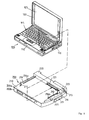
- Fig. 1 is a diagram illustrating the external appearance of a docking unit 200.
- the docking unit 200 comprises two independent sections that can be physically coupled with and separated from each other: an upper section 200a and a lower section 200b.
- the upper section 200a of the docking unit 200 includes a security key 213, a first shutter 216, and a hook 215.
- the lower section 200b of the docking unit 200 includes a second shutter 333.
- a notebook computer 100 is a personal computer comprising a shallow-bottom main body 110, and a lid 120 rotatably attached at the almost rear edge of the main body 110.
- the footprint of the notebook computer 100 is, for example, the size of a sheet of A4 paper.
- a keyboard unit 115 is mounted on top of the main body 110, and a liquid crystal display (LCD) 125 is fitted inside the inner face of the lid 120.
- LCD liquid crystal display
- the notebook computer 100 a docking connector (not shown) formed on its rear face. Also, formed in the bottom face are a pair of linear grooves (not shown) into which a pair of linear protrusions (described later) are to be inserted into and along which they are guided, and an opening on the docking unit 200 side (not shown) for engaging the hook 215 (described later). Further, a card exchange port 118 is formed in the left side of the notebook computer 100, so that a PC card can be detached and exchanged.
- Such a notebook computer 100 is the "IBM ThinkPad 760" ("ThinkPad” is a trademark of IBM Corp.) sold by IBM Japan, Ltd. It should be noted that the structure of the notebook computer is not the subject of the present invention.
- the docking unit 200 comprises a mounting portion 210 on which the notebook computer 100 is mounted, and a projection portion 220 projected upward at the rear of the mounting portion 210.
- the mounting portion 210 is a thin and rigid structure that has a width and a depth that correspond to the footprint of the notebook computer 100.
- a side wall 211 is defined at the left end of the mounting portion 210, while a security link cover 212 is provided on the right end.
- the security link cover 212 is a member that covers and hides a transmission mechanism (described later) that transmits the rotation of a security key 213 (i.e. key position) to the individual sections.
- the transmission mechanism is employed to set the docking unit 200 to a predetermined security mode (which will be described later).
- the rotation of the security key 213 is transmitted, for example, to the hook 215, which is located substantially at the front on the mounting portion 210; the first shutter 216, which is provided upright on the top of the security link cover 212; and the second shutter 333, which is provided perpendicularly on the right side of the docking unit 200 (described later).
- a distance between the side wall 211 and the internal wall of the link cover 212 is formed about the same as the width of the notebook computer 100 in the direction of the depth.
- a pair of linear protrusions 214a and 214b protrude upward along the right and the left side of the top face of the mounting portion 210, and form a predetermined distance in the direction of the depth.
- a connector 221 is firmly fixed within the right front face of the projection portion 220 that is provided at the rear of the docking unit 200, and is employed for connection to the notebook computer 100.
- the electrical and mechanical specifications of the connector 221 match those of the docking connector of the notebook computer 100.
- the connector 221 consists, for example, of a terminal having 240 pins which includes various port signal pins and a bus signal pin.
- the electrical circuit mainly plays the role of separating the signal pins of the connector 221 into the port signal pins and the bus signal pins.
- the signal pins are separated in such manner because the docking unit 200 has a portion that performs the port replication function and a portion that performs the bus expansion function.
- the eject position is a key position at which the mounted notebook computer 100 is ejected
- the unlocked position is a key position at which the notebook computer 100 is not locked in place so that it can be mounted, even though it can be mounted
- the locked position is a key position at which the removal of both the mounted notebook computer 100 and a loaded PC card is inhibited.
- the rotation of the security key 213 is transmitted to the individual sections of the docking unit 200 by the transmission mechanism in the link cover 212 (described later), so that these sections perform predetermined operations.
- An indicator 223 is provided on the top right end of the projection portion 220 to display a key position.
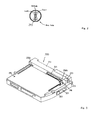
- Fig. 3 is shown the status where the security key 213 is placed at the eject position.
- a pair of ejectors 250a and 250b interact and project outward from the right and left front of the projection portion 220.
- the ejectors 250a and 250b abut against the mounted notebook computer 100 (not shown in Fig. 3) and drive it forward.
- a resisting force for returning from the eject position to the unlocked position constantly acts on the security key 213.
- the function is provided based on the reasoning that the eject operation should be performed only temporarily, and that the security key 213 must normally be at the unlocked position at which a notebook computer 100 can be mounted.
- the key operation is required for conditions other than the locked condition, and that the removal of the key is not required, removal of the security key 213 from the key hole is prevented while it is at the eject position or at the unlocked position. Since the security key 213 is always inserted, a plurality of users can share a single docking unit (multi-user mode).
- the state where the security key 213 has been turned until it is almost vertical is the unlocked state.
- the unlocked state is a neutral state between the eject position and the locked position.
- One action that accompanies the shift to the locked position involves the employment of the hook 215 to inhibit the removal of the notebook computer 100.
- the hook 215 In the unlocked condition, the hook 215 is freely extracted from the notebook computer 100 and is retracted into the mounting portion 210 (see Fig. 8).
- the security key 213 is turned to the locked position, the hook 215 interlocks with the notebook computer 100 and is fixed in the extended state, and the retraction of the hook 215 into the mounting portion 210 is inhibited.
- the hook 215 is maintained in a position where it engages the opening formed in the corresponding portion at the bottom of the notebook computer 100, and the removal of the notebook computer 100 is strictly inhibited.
- Another action that accompanies the shift to the locked position is the inhibition of the removal of a PC card from the PC card slot 118 of the notebook computer 100.
- the card slot 118 is on the about rear left side of the notebook computer 100.
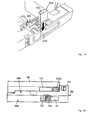
- the first shutter 216 is located upright on the top of the link cover 212 of the docking unit 200. As is shown in Fig. 10, the first shutter 216 interacts with the rotation of the security key 213 and slides forward and backward.
- the first shutter 216 is positioned at the rear (A) and the card slot 118 of the notebook computer 100 is fully opened.
- the locked position however, the first shutter 216 slides forward and shields at least one part of the card slot 118 (B). As a result, the removal of the PC card is desirably inhibited.
- An additional action that accompanies the shift to the locked position is the inhibition of the removal of a PC card from the PC card slot 331 in the lower section 200b of the docking unit 200.
- the card slot 331 is at the about rear left side of: the docking unit 200
- the second shutter 333 is vertically formed in the about center of the left side of the docking unit 200.
- the second shutter 333 interacts with the rotation of the security key 213, and slides forward and backward.
- the second shutter 333 is positioned almost in the center (A) and the card slot 331 of the docking unit 200 is fully opened (see Fig. 6).
- the second shutter 333 slides backward and shields at least one part of the card slot 331 (B). As a result, the removal of a PC card is inhibited.
- a further action that accompanies the shift to the locked position is the inhibition of the separation of the upper section 200a of the docking unit 200 and the lower section 200b of the docking unit 200. Since the separation of these sections is inhibited, peripheral devices (e.g., an HDD, a CD-ROM, and an FDD that are retained in a media bay) in the docking unit 200 can be protected from being accidentally removed.
- peripheral devices e.g., an HDD, a CD-ROM, and an FDD that are retained in a media bay
- the removal of the security key 213 is permitted at the locked position. This prevents an unauthorized user from operating the key, and provides physical security.
- Figs. 11 through 14 The structure of the ejectors 250a and 250b (hereafter referred to, as a pair, as the ejectors 250) at the eject position will now be explained while referring to schematic diagrams in Figs. 11 through 14.
- Figs. 11 and 12 are shown the ejectors 250 when they are at the unlocked position.
- the external frame of the docking unit 200 is delineated by broken lines so that it can be understood that the interior of the docking unit 200 is depicted.
- the ejectors 250 are stored inside the docking unit 200. This state is the same as when the security key 213 is situated at the locked position.
- Figs. 11 and 12 are shown the ejectors 250 when they are at the unlocked position.
- the external frame of the docking unit 200 is delineated by broken lines so that it can be understood that the interior of the docking unit 200 is depicted.
- the ejectors 250 are stored inside the docking unit 200. This
- a cam 500 pushes forward a protrusion 515 of a coupling member 510 that is connected to the ejector 250a.
- the coupling member 510 rotates around a coupling rod 530, which serves as a rotary shaft.
- a portion of the ejector 250a is extended outward from the docking unit 200, through an ejector port 255, and pushes against the left rear portion of the notebook computer 100 (not shown).
- the rotation of the coupling member 510 is transmitted to the coupling rod 530, and a coupling member 520 that is fitted over the coupling rod 530 is rotated in the same direction.
- a portion of the ejector 250b is also extended outward from the docking unit 200, through an ejector port 255, and pushes against the right rear end of the notebook computer 100 (not shown).
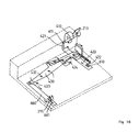
- Fig. 15 is shown the internal structure of the upper section 200a of the docking unit 200 when the security key 213 is situated at the unlocked position.
- the internal mechanism comprises:
- Fig. 16 are shown the movements of the individual components of the internal mechanism when the security key 213 is rotated to the locked position.
- the first shutter 216 can be replaced with one that is so shaped that it corresponds to the position of the PC card slot 118 of the notebook computer 100.
- the sliding of the second shutter 333 of the lower section 200b of the docking unit 200 will be explained.
- the docking unit 200 can be separated into the upper section 200a and the lower section 200b.
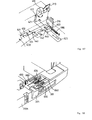
- the structure of the second shutter 333 in the lower section 200b of the docking unit 200 is shown in Fig. 18.
- a lower slide 600 is coupled with the lower section 200b by a spring 620.
- the lower slide 600 reciprocates inside a slide frame 640.
- the second shutter 333 is fixed to and slides together with the lower slide 600.
- a protrusion 610 of the lower slide 600 extends into the upper section 200a of the docking unit 200 (see Fig. 16).
- the security key 213 is turned and is situated at the locked position, the slide plate 420 slides backwards in the previously described manner.
- the protrusion 610 of the lower slide 600 that extends through an opening 422 in the slide plate 420 is also moved backward together with the slide plate 420.
- the lower slide 600 is moved in the direction indicated by A, and the second shutter 333 is also shifted in the same direction, and shields one part of the PC card slot 331.
- the PC card that is inserted inside the lower section 200b of the docking unit 200 can be protected (see Fig. 10).
- An opening 630 is formed in the slide frame 640 of the lower section 200b of the docking unit 200. This opening 630 is located at a fixed position inside the lower section 200b (see Fig. 18). As is shown in Fig. 19, an L-shaped plug 650 is so attached that a protrusion 655 of the plug 650 is inserted into and fitted in the opening 630. Thus, the lower slide 600 cannot slide and the protrusion 610 of the lower slide 600 is also fixed. Therefore, in Fig. 15, the slide plate 420 is halted by securing the protrusion 610, and the rotation of the security key 213 to the locked position is inhibited.
- an excellent docking unit that is coupled with a portable computer, and that can protect the portable computer and its peripheral devices.
- an excellent docking unit that can protect the portable computer and peripheral devices accommodated into itself in accordance with a mode that is user selected.
Landscapes
- Engineering & Computer Science (AREA)
- Theoretical Computer Science (AREA)
- Human Computer Interaction (AREA)
- Physics & Mathematics (AREA)
- General Engineering & Computer Science (AREA)
- General Physics & Mathematics (AREA)
- Computer Hardware Design (AREA)
- Casings For Electric Apparatus (AREA)
- Calculators And Similar Devices (AREA)
Applications Claiming Priority (3)
| Application Number | Priority Date | Filing Date | Title |
|---|---|---|---|
| JP8073669A JPH09269848A (ja) | 1996-03-28 | 1996-03-28 | 携帯型コンピュータ用ドッキング装置 |
| JP73669/96 | 1996-03-28 | ||
| JP7366996 | 1996-03-28 |
Publications (3)
| Publication Number | Publication Date |
|---|---|
| EP0798622A2 true EP0798622A2 (de) | 1997-10-01 |
| EP0798622A3 EP0798622A3 (de) | 1999-07-28 |
| EP0798622B1 EP0798622B1 (de) | 2003-09-10 |
Family
ID=13524890
Family Applications (1)
| Application Number | Title | Priority Date | Filing Date |
|---|---|---|---|
| EP97301140A Expired - Lifetime EP0798622B1 (de) | 1996-03-28 | 1997-02-21 | Gesicherte Dockingeinheit für einen tragbaren Rechner |
Country Status (6)
| Country | Link |
|---|---|
| US (1) | US5870283A (de) |
| EP (1) | EP0798622B1 (de) |
| JP (1) | JPH09269848A (de) |
| KR (1) | KR100246867B1 (de) |
| DE (1) | DE69724684D1 (de) |
| TW (1) | TW479163B (de) |
Cited By (3)
| Publication number | Priority date | Publication date | Assignee | Title |
|---|---|---|---|---|
| US7426108B2 (en) * | 2006-06-30 | 2008-09-16 | Carnevali Jeffrey D | Portable device docking station |
| EP1653327A3 (de) * | 2004-10-28 | 2008-11-19 | Hewlett-Packard Development Company, L.P. | Andockstation |
| US8179672B2 (en) | 2006-06-30 | 2012-05-15 | National Products, Inc. | Portable device docking station |
Families Citing this family (55)
| Publication number | Priority date | Publication date | Assignee | Title |
|---|---|---|---|---|
| US5959835A (en) * | 1996-03-29 | 1999-09-28 | Sanyo Electric Co., Ltd. | Attachment device of portable electronic equipment and feature expanding unit of portable electronic equipment, and separation type feature expanding device of portable electronic equipment comprising attachment device and feature expanding unit |
| KR100195868B1 (ko) * | 1996-12-09 | 1999-06-15 | 윤종용 | 확장시스템과의 결합전 전원차단기능을 갖는 컴퓨터 및 컴퓨터시스템 |
| KR100455649B1 (ko) * | 1997-03-10 | 2004-12-29 | 삼성전자주식회사 | 주변장치의착탈잠금제어장치및그방법 |
| JP3718317B2 (ja) | 1997-04-23 | 2005-11-24 | 株式会社日立製作所 | 情報処理装置、及び情報処理関連装置 |
| KR19990015963U (ko) * | 1997-10-22 | 1999-05-15 | 윤종용 | 휴대용 컴퓨터의 보조기기 잠금장치 |
| US6072695A (en) * | 1997-10-30 | 2000-06-06 | Hewlett-Packard Company | Horizontal loading docking station with uninterrupted power supply |
| JPH11185926A (ja) | 1997-12-25 | 1999-07-09 | Yazaki Corp | コネクタ、コネクタの製造方法及びこの製造方法に用いられる型構造 |
| US5924878A (en) * | 1998-03-17 | 1999-07-20 | Compal Electronics, Inc. | Protection device for expansion device of portable computer |
| US6151218A (en) * | 1998-08-21 | 2000-11-21 | Compaq Computer Corporation | Physical security system for portable computer/port replicator |
| CA2246139A1 (en) * | 1998-08-26 | 2000-02-26 | Computer Security Devices Inc. | Laptop computer security device |
| US6560103B1 (en) * | 1998-09-22 | 2003-05-06 | Sanyo Electric Co., Ltd. | Accessory of electronic device |
| JP3176345B2 (ja) * | 1998-10-21 | 2001-06-18 | 米沢日本電気株式会社 | ノート型パーソナルコンピュータ用ポートリプリケータ解除機構のストッパの動作不能の防止機構 |
| US6275378B1 (en) * | 1999-01-19 | 2001-08-14 | Compal Electronics, Inc. | Safety lock for notebook-type computer dock |
| US6015308A (en) * | 1999-02-01 | 2000-01-18 | Compal Electronics, Inc. | Docking station for a notebook computer |
| US6061234A (en) * | 1999-03-15 | 2000-05-09 | Dell U.S.A., L.P. | Secured snap-on cover for a computer system docking station |
| JP2000305845A (ja) * | 1999-04-16 | 2000-11-02 | Internatl Business Mach Corp <Ibm> | コンピュータ用拡張ユニットにおけるセキュリティシステム |
| US6189349B1 (en) * | 1999-05-28 | 2001-02-20 | Hewlett-Packard Company | Single retracting security hook of desktop port replicator providing security for dissimilar multiple portable computers |
| US6129430A (en) * | 1999-06-03 | 2000-10-10 | Inventec Corp. | Stylus removal mechanism |
| JP4695318B2 (ja) | 1999-08-05 | 2011-06-08 | エムアーペー メディツィンテクノロジー ゲゼルシャフト・ミット・ベシュレンクテル・ハフツング | 呼気ガスを供給する装置、加湿装置、呼吸用チューブ接続デバイス、呼吸用チューブ及び接続構造 |
| TW468713U (en) * | 2000-10-17 | 2001-12-11 | Sinox Co Ltd | Locking device for mini computer |
| KR20020041631A (ko) * | 2000-11-28 | 2002-06-03 | 윤종용 | 휴대용 컴퓨터로부터 도킹 스테이션을 분리하는 방법 |
| US6459574B1 (en) * | 2000-12-28 | 2002-10-01 | Intel Corporation | Docking station having a cooling unit to cool an electronic device |
| WO2002066106A1 (en) | 2001-02-16 | 2002-08-29 | Resmed Limited | Humidifier with structure to prevent backflow of liquid through the humidifier inlet |
| US6549416B2 (en) * | 2001-03-15 | 2003-04-15 | Hewlett Packard Development Company, L.P. | Portable computer docking station with protected connector |
| US6683786B2 (en) * | 2002-01-07 | 2004-01-27 | Hewlett-Packard Development Company, L.P. | Portable computer docking station with movable electrical interface |
| KR100439719B1 (ko) | 2002-01-08 | 2004-07-12 | 삼성전자주식회사 | 노트북 컴퓨터 |
| TW547905U (en) * | 2002-06-13 | 2003-08-11 | Wistron Corp | Fastener |
| KR100906248B1 (ko) | 2002-10-16 | 2009-07-07 | 삼성전자주식회사 | 도킹스테이션 및 이를 이용한 노트북 컴퓨터 |
| US6885552B2 (en) * | 2002-12-20 | 2005-04-26 | Dell Products L.P. | System and method for a multi-functional security mechanism in a docking station |
| US7379295B2 (en) * | 2003-04-09 | 2008-05-27 | Arima Computer Corporation | One-touch release apparatus |
| DE202004021798U1 (de) | 2003-06-20 | 2011-02-10 | ResMed Ltd., Bella Vista | Atemgasvorrichtung mit Befeuchter |
| AU2003903139A0 (en) | 2003-06-20 | 2003-07-03 | Resmed Limited | Breathable gas apparatus with humidifier |
| US7201407B2 (en) * | 2003-06-25 | 2007-04-10 | Southco, Inc. | Sliding panel latch |
| US7227747B2 (en) * | 2004-10-20 | 2007-06-05 | Hewlett-Packard Development Company, L.P. | Securing computer equipment |
| US7345871B2 (en) * | 2005-02-01 | 2008-03-18 | Hewlett-Packard Development Company, L.P. | System and method for locking a tablet computer display |
| US7298611B1 (en) * | 2006-06-30 | 2007-11-20 | Carnevali Jeffrey D | Portable device docking station |
| US7471508B2 (en) * | 2006-07-01 | 2008-12-30 | Lenovo (Singapore) Pte. Ltd. | System and method for locking computer |
| CN101153525B (zh) * | 2006-09-30 | 2013-01-09 | Ge医疗系统环球技术有限公司 | 连接/断开机构及组合装置 |
| US7978466B2 (en) * | 2008-02-27 | 2011-07-12 | L&P Property Management Company | Computer docking station for a vehicle |
| JP4511609B2 (ja) | 2008-05-19 | 2010-07-28 | レノボ・シンガポール・プライベート・リミテッド | ドッキング装置 |
| NZ727179A (en) | 2008-06-05 | 2018-06-29 | Resmed Ltd | Treatment of respiratory conditions |
| TWM364235U (en) * | 2009-04-28 | 2009-09-01 | Pegatron Corp | Base and electronic apparatus using the same |
| US8931481B2 (en) | 2009-06-04 | 2015-01-13 | Redmed Limited | Flow generator chassis assembly with suspension seal |
| TW201118232A (en) * | 2009-11-18 | 2011-06-01 | Inventec Corp | Lock |
| USD651616S1 (en) * | 2010-05-10 | 2012-01-03 | Devin Kain | ipod docking station |
| US8427826B2 (en) | 2010-11-29 | 2013-04-23 | L&P Property Management Company | Computer docking station assembly |
| USD706261S1 (en) | 2012-01-24 | 2014-06-03 | Intel Corporation | Mobile computing device |
| CN107102688B (zh) | 2012-01-24 | 2022-06-14 | 英特尔公司 | 移动计算设备、装置和系统 |
| US9429993B2 (en) * | 2013-11-21 | 2016-08-30 | Toshiba Global Commerce Solutions Holdings Corporation | Computing device docking systems |
| EP3590024B1 (de) | 2017-03-01 | 2021-12-08 | Acco Brands Corporation | Dock für tragbare elektronische vorrichtung |
| US10917986B2 (en) | 2018-03-08 | 2021-02-09 | ACCO Brands Corporation | Dock for a portable electronic device |
| US10067533B1 (en) * | 2018-03-27 | 2018-09-04 | Precision Mounting Technologies Ltd. | Locking dock for portable electronic device |
| USD892123S1 (en) | 2018-07-16 | 2020-08-04 | ACCO Brands Corporation | Dock for a portable electronic device |
| USD899598S1 (en) | 2018-09-04 | 2020-10-20 | 3B Medical, Inc. | CPAP device |
| TWI739698B (zh) * | 2020-12-24 | 2021-09-11 | 和碩聯合科技股份有限公司 | 擴充裝置及電子系統 |
Family Cites Families (4)
| Publication number | Priority date | Publication date | Assignee | Title |
|---|---|---|---|---|
| CA2071381C (en) * | 1991-07-19 | 1998-12-15 | Youji Satou | Electronic apparatus, card-type electronic component used with the electronic apparatus, and electronic system with expanding apparatus for expanding function of electronic apparatus |
| JPH087646B2 (ja) * | 1992-10-29 | 1996-01-29 | インターナショナル・ビジネス・マシーンズ・コーポレイション | 携帯型コンピュータ用据置装置 |
| JP2596702B2 (ja) * | 1993-07-23 | 1997-04-02 | インターナショナル・ビジネス・マシーンズ・コーポレイション | 情報処理装置 |
| US5757616A (en) * | 1996-10-31 | 1998-05-26 | Hewlett-Packard Company | Physical security system for portable computer |
-
1996
- 1996-03-28 JP JP8073669A patent/JPH09269848A/ja active Pending
- 1996-04-01 TW TW085103988A patent/TW479163B/zh not_active IP Right Cessation
- 1996-12-13 KR KR1019960065312A patent/KR100246867B1/ko not_active Expired - Fee Related
-
1997
- 1997-02-21 DE DE69724684T patent/DE69724684D1/de not_active Expired - Lifetime
- 1997-02-21 EP EP97301140A patent/EP0798622B1/de not_active Expired - Lifetime
- 1997-03-28 US US08/828,453 patent/US5870283A/en not_active Expired - Fee Related
Cited By (4)
| Publication number | Priority date | Publication date | Assignee | Title |
|---|---|---|---|---|
| EP1653327A3 (de) * | 2004-10-28 | 2008-11-19 | Hewlett-Packard Development Company, L.P. | Andockstation |
| US7426108B2 (en) * | 2006-06-30 | 2008-09-16 | Carnevali Jeffrey D | Portable device docking station |
| US8179672B2 (en) | 2006-06-30 | 2012-05-15 | National Products, Inc. | Portable device docking station |
| US9036343B2 (en) | 2006-06-30 | 2015-05-19 | National Products, Inc. | Portable device docking station |
Also Published As
| Publication number | Publication date |
|---|---|
| TW479163B (en) | 2002-03-11 |
| KR970066794A (ko) | 1997-10-13 |
| KR100246867B1 (ko) | 2000-03-15 |
| US5870283A (en) | 1999-02-09 |
| EP0798622B1 (de) | 2003-09-10 |
| EP0798622A3 (de) | 1999-07-28 |
| JPH09269848A (ja) | 1997-10-14 |
| DE69724684D1 (de) | 2003-10-16 |
Similar Documents
| Publication | Publication Date | Title |
|---|---|---|
| EP0798622B1 (de) | Gesicherte Dockingeinheit für einen tragbaren Rechner | |
| US6570758B1 (en) | Docking unit for portable computer | |
| EP0525368B1 (de) | Elektronische Vorrichtung mit einer abnehmbaren Einheit ausgerüstet | |
| US5818691A (en) | Portable computer docking system with push to engage and push to disengage connection module | |
| KR100439719B1 (ko) | 노트북 컴퓨터 | |
| JP4071325B2 (ja) | ポータブルコンピュータ装置 | |
| US5619397A (en) | Electronic device system including a portable electronic device having a handwriting input device locked to an expansion station when the power switch of the portable electronic device is turned on | |
| US5805412A (en) | Multiple stacked docking stations and portable computer | |
| US5364196A (en) | Portable computer with integral printer | |
| KR970002362B1 (ko) | 커넥터 장치 | |
| US5477415A (en) | Automatic computer docking station having a motorized tray, cammed side connectors, motorized side connectors, and locking and unlocking guide pins | |
| JP4091629B2 (ja) | コンピュータ固定装置 | |
| CN100462894C (zh) | 用于接收信息处理装置机身的扩展设备 | |
| US6115245A (en) | Computer docking station with half-height bays and associated security system | |
| US5933322A (en) | Computer docking station with integral base security system | |
| JP2001067146A (ja) | コンピューター用拡張ユニットのロック装置 | |
| GB2417977A (en) | Push-push latch mechanism for retaining a component in a device | |
| US6760228B1 (en) | Apparatus for securing a removable circuit card in a computing system | |
| WO2009098780A1 (ja) | 情報機器用機能拡張ユニット | |
| JPH03294917A (ja) | 携帯型コンピュータの機能拡張用ステーション | |
| JP2000039933A (ja) | 電子機器システムおよび電子機器の機能を拡張するための拡張装置 | |
| JP4393597B2 (ja) | Pcカードイジェクト機構 | |
| WO2021221670A1 (en) | Storage drive adapters with drive cartridges | |
| JPH0613143A (ja) | コネクタ装置 | |
| HK1014284A1 (en) | Information processing apparatus |
Legal Events
| Date | Code | Title | Description |
|---|---|---|---|
| PUAI | Public reference made under article 153(3) epc to a published international application that has entered the european phase |
Free format text: ORIGINAL CODE: 0009012 |
|
| AK | Designated contracting states |
Kind code of ref document: A2 Designated state(s): DE FR GB |
|
| PUAL | Search report despatched |
Free format text: ORIGINAL CODE: 0009013 |
|
| AK | Designated contracting states |
Kind code of ref document: A3 Designated state(s): DE FR GB |
|
| 17P | Request for examination filed |
Effective date: 20000112 |
|
| 17Q | First examination report despatched |
Effective date: 20020430 |
|
| GRAH | Despatch of communication of intention to grant a patent |
Free format text: ORIGINAL CODE: EPIDOS IGRA |
|
| GRAS | Grant fee paid |
Free format text: ORIGINAL CODE: EPIDOSNIGR3 |
|
| GRAA | (expected) grant |
Free format text: ORIGINAL CODE: 0009210 |
|
| AK | Designated contracting states |
Kind code of ref document: B1 Designated state(s): DE FR GB |
|
| PG25 | Lapsed in a contracting state [announced via postgrant information from national office to epo] |
Ref country code: FR Free format text: LAPSE BECAUSE OF FAILURE TO SUBMIT A TRANSLATION OF THE DESCRIPTION OR TO PAY THE FEE WITHIN THE PRESCRIBED TIME-LIMIT Effective date: 20030910 |
|
| REG | Reference to a national code |
Ref country code: GB Ref legal event code: FG4D |
|
| REF | Corresponds to: |
Ref document number: 69724684 Country of ref document: DE Date of ref document: 20031016 Kind code of ref document: P |
|
| PG25 | Lapsed in a contracting state [announced via postgrant information from national office to epo] |
Ref country code: DE Free format text: LAPSE BECAUSE OF FAILURE TO SUBMIT A TRANSLATION OF THE DESCRIPTION OR TO PAY THE FEE WITHIN THE PRESCRIBED TIME-LIMIT Effective date: 20031211 |
|
| PLBE | No opposition filed within time limit |
Free format text: ORIGINAL CODE: 0009261 |
|
| STAA | Information on the status of an ep patent application or granted ep patent |
Free format text: STATUS: NO OPPOSITION FILED WITHIN TIME LIMIT |
|
| 26N | No opposition filed |
Effective date: 20040614 |
|
| EN | Fr: translation not filed | ||
| PGFP | Annual fee paid to national office [announced via postgrant information from national office to epo] |
Ref country code: GB Payment date: 20050202 Year of fee payment: 9 |
|
| PG25 | Lapsed in a contracting state [announced via postgrant information from national office to epo] |
Ref country code: GB Free format text: LAPSE BECAUSE OF NON-PAYMENT OF DUE FEES Effective date: 20060221 |
|
| REG | Reference to a national code |
Ref country code: GB Ref legal event code: 732E |
|
| GBPC | Gb: european patent ceased through non-payment of renewal fee |
Effective date: 20060221 |