EP0797940A1 - Ensemble d'application d'un produit fluide ou pâteux - Google Patents
Ensemble d'application d'un produit fluide ou pâteux Download PDFInfo
- Publication number
- EP0797940A1 EP0797940A1 EP97400616A EP97400616A EP0797940A1 EP 0797940 A1 EP0797940 A1 EP 0797940A1 EP 97400616 A EP97400616 A EP 97400616A EP 97400616 A EP97400616 A EP 97400616A EP 0797940 A1 EP0797940 A1 EP 0797940A1
- Authority
- EP
- European Patent Office
- Prior art keywords
- assembly according
- support
- application
- application assembly
- reservoir
- Prior art date
- Legal status (The legal status is an assumption and is not a legal conclusion. Google has not performed a legal analysis and makes no representation as to the accuracy of the status listed.)
- Granted
Links
- 239000012530 fluid Substances 0.000 title description 2
- 210000002105 tongue Anatomy 0.000 claims description 20
- 230000000295 complement effect Effects 0.000 claims description 11
- 239000002781 deodorant agent Substances 0.000 claims description 7
- 230000006835 compression Effects 0.000 claims description 4
- 238000007906 compression Methods 0.000 claims description 4
- 238000004891 communication Methods 0.000 claims description 3
- 238000003825 pressing Methods 0.000 claims description 2
- 239000003380 propellant Substances 0.000 claims description 2
- 239000000463 material Substances 0.000 abstract description 3
- 239000000047 product Substances 0.000 description 33
- 238000006073 displacement reaction Methods 0.000 description 4
- 208000033641 Ring chromosome 5 syndrome Diseases 0.000 description 2
- 239000002537 cosmetic Substances 0.000 description 2
- 238000009826 distribution Methods 0.000 description 2
- 238000012423 maintenance Methods 0.000 description 2
- 230000014759 maintenance of location Effects 0.000 description 2
- 230000002093 peripheral effect Effects 0.000 description 2
- 238000007789 sealing Methods 0.000 description 2
- 239000012080 ambient air Substances 0.000 description 1
- 239000011324 bead Substances 0.000 description 1
- 230000000903 blocking effect Effects 0.000 description 1
- 230000015556 catabolic process Effects 0.000 description 1
- 238000002788 crimping Methods 0.000 description 1
- 238000006731 degradation reaction Methods 0.000 description 1
- 230000002951 depilatory effect Effects 0.000 description 1
- 238000001035 drying Methods 0.000 description 1
- 230000000694 effects Effects 0.000 description 1
- 239000006260 foam Substances 0.000 description 1
- 239000003292 glue Substances 0.000 description 1
- 239000000077 insect repellent Substances 0.000 description 1
- 239000007788 liquid Substances 0.000 description 1
- 238000004519 manufacturing process Methods 0.000 description 1
- 230000004048 modification Effects 0.000 description 1
- 238000012986 modification Methods 0.000 description 1
- 210000000056 organ Anatomy 0.000 description 1
- 239000003973 paint Substances 0.000 description 1
- 235000011837 pasties Nutrition 0.000 description 1
- 230000035515 penetration Effects 0.000 description 1
- 239000011435 rock Substances 0.000 description 1
- 238000000926 separation method Methods 0.000 description 1
- 238000007493 shaping process Methods 0.000 description 1
- 239000012265 solid product Substances 0.000 description 1
Images


Classifications
-
- B—PERFORMING OPERATIONS; TRANSPORTING
- B05—SPRAYING OR ATOMISING IN GENERAL; APPLYING FLUENT MATERIALS TO SURFACES, IN GENERAL
- B05C—APPARATUS FOR APPLYING FLUENT MATERIALS TO SURFACES, IN GENERAL
- B05C17/00—Hand tools or apparatus using hand held tools, for applying liquids or other fluent materials to, for spreading applied liquids or other fluent materials on, or for partially removing applied liquids or other fluent materials from, surfaces
- B05C17/005—Hand tools or apparatus using hand held tools, for applying liquids or other fluent materials to, for spreading applied liquids or other fluent materials on, or for partially removing applied liquids or other fluent materials from, surfaces for discharging material from a reservoir or container located in or on the hand tool through an outlet orifice by pressure without using surface contacting members like pads or brushes
- B05C17/01—Hand tools or apparatus using hand held tools, for applying liquids or other fluent materials to, for spreading applied liquids or other fluent materials on, or for partially removing applied liquids or other fluent materials from, surfaces for discharging material from a reservoir or container located in or on the hand tool through an outlet orifice by pressure without using surface contacting members like pads or brushes with manually mechanically or electrically actuated piston or the like
- B05C17/0116—Hand tools or apparatus using hand held tools, for applying liquids or other fluent materials to, for spreading applied liquids or other fluent materials on, or for partially removing applied liquids or other fluent materials from, surfaces for discharging material from a reservoir or container located in or on the hand tool through an outlet orifice by pressure without using surface contacting members like pads or brushes with manually mechanically or electrically actuated piston or the like characterised by the piston driving means
- B05C17/0133—Nut and bolt advancing mechanism, e.g. threaded piston rods
-
- A—HUMAN NECESSITIES
- A45—HAND OR TRAVELLING ARTICLES
- A45D—HAIRDRESSING OR SHAVING EQUIPMENT; EQUIPMENT FOR COSMETICS OR COSMETIC TREATMENTS, e.g. FOR MANICURING OR PEDICURING
- A45D34/00—Containers or accessories specially adapted for handling liquid toiletry or cosmetic substances, e.g. perfumes
- A45D34/04—Appliances specially adapted for applying liquid, e.g. using roller or ball
- A45D34/042—Appliances specially adapted for applying liquid, e.g. using roller or ball using a brush or the like
-
- A—HUMAN NECESSITIES
- A45—HAND OR TRAVELLING ARTICLES
- A45D—HAIRDRESSING OR SHAVING EQUIPMENT; EQUIPMENT FOR COSMETICS OR COSMETIC TREATMENTS, e.g. FOR MANICURING OR PEDICURING
- A45D40/00—Casings or accessories specially adapted for storing or handling solid or pasty toiletry or cosmetic substances, e.g. shaving soaps or lipsticks
- A45D40/02—Casings wherein movement of the lipstick or like solid is a sliding movement
- A45D40/04—Casings wherein movement of the lipstick or like solid is a sliding movement effected by a screw
-
- B—PERFORMING OPERATIONS; TRANSPORTING
- B05—SPRAYING OR ATOMISING IN GENERAL; APPLYING FLUENT MATERIALS TO SURFACES, IN GENERAL
- B05C—APPARATUS FOR APPLYING FLUENT MATERIALS TO SURFACES, IN GENERAL
- B05C17/00—Hand tools or apparatus using hand held tools, for applying liquids or other fluent materials to, for spreading applied liquids or other fluent materials on, or for partially removing applied liquids or other fluent materials from, surfaces
- B05C17/002—Hand tools or apparatus using hand held tools, for applying liquids or other fluent materials to, for spreading applied liquids or other fluent materials on, or for partially removing applied liquids or other fluent materials from, surfaces with feed system for supplying material from an external source; Supply controls therefor
-
- B—PERFORMING OPERATIONS; TRANSPORTING
- B65—CONVEYING; PACKING; STORING; HANDLING THIN OR FILAMENTARY MATERIAL
- B65D—CONTAINERS FOR STORAGE OR TRANSPORT OF ARTICLES OR MATERIALS, e.g. BAGS, BARRELS, BOTTLES, BOXES, CANS, CARTONS, CRATES, DRUMS, JARS, TANKS, HOPPERS, FORWARDING CONTAINERS; ACCESSORIES, CLOSURES, OR FITTINGS THEREFOR; PACKAGING ELEMENTS; PACKAGES
- B65D47/00—Closures with filling and discharging, or with discharging, devices
- B65D47/42—Closures with filling and discharging, or with discharging, devices with pads or like contents-applying means
-
- A—HUMAN NECESSITIES
- A45—HAND OR TRAVELLING ARTICLES
- A45D—HAIRDRESSING OR SHAVING EQUIPMENT; EQUIPMENT FOR COSMETICS OR COSMETIC TREATMENTS, e.g. FOR MANICURING OR PEDICURING
- A45D2200/00—Details not otherwise provided for in A45D
- A45D2200/10—Details of applicators
- A45D2200/1009—Applicators comprising a pad, tissue, sponge, or the like
- A45D2200/1018—Applicators comprising a pad, tissue, sponge, or the like comprising a pad, i.e. a cushion-like mass of soft material, with or without gripping means
Definitions
- the invention relates to an assembly for applying a fluid or solid product to a surface to be treated.
- the application assembly can in particular be used in the cosmetic field for the application of a deodorant, in the pharmaceutical field for the application of insect repellents, as well as in the fields of glues, paints or polishes.
- this application set is intended for the application of a body deodorant.
- Document FR-A-2 713 060 in the name of the applicant, describes an application assembly comprising a reservoir of pressurized product, provided with a dispensing valve and an application member comprising a porous dome, attached to the tank.
- This dome is maintained by a support mechanically linked to a hoop fixed on the tank.
- the porous dome is soaked with product.
- the product soaked in the dome can cause a modification of the volume of the dome and in particular a reduction of the latter.
- This variation in volume can cause a decrease in the retention of the dome on the support.
- the dome may detach from the support and fall. The applicator is then no longer usable and it is not possible to replace the dome on the support.
- the present invention therefore aims to remedy the drawbacks mentioned above.
- the present invention aims, above all, to propose an application assembly which avoids the separation of the dome from the support. It aims in particular to strengthen the maintenance of the dome on the support.
- the present invention therefore relates to a set for applying a product comprising a reservoir for the product to be dispensed, provided with an outlet for the product, a member for applying the product in communication with the reservoir, having an external surface. of application and carried by a support fixed on the product outlet from the reservoir, characterized in that the support comprises elastically deformable fixing means capable of holding the application member fixed on the support.
- said elastically deformable fixing means are locked in the position for holding the applicator member when the support is fixed to the product outlet.
- the fixing means are elastically deformable in a direction substantially perpendicular to an axis of symmetry (X) of the tank.
- these fixing means exert a radial force on the application member.
- the applicator member can advantageously include at least one attachment surface in which the elastically deformable fixing means are fixed.
- the attachment surface is in the form of a cylinder disposed substantially along the axis X and centered on this axis, so as to allow a regular distribution of the fixing means fixed in the attachment surface.
- the elastically deformable fixing means allow the applicator member to be replaced when the latter detaches from the support. It is also possible to change the application organ at will.
- the application assembly according to the invention comprises an interchangeable application member.
- the elastically deformable fixing means are locked in the holding position of the application member before the support is fixed on the product outlet.
- the application assembly comprises a skirt bearing radially on the fixing means, allowing good locking of the latter in the holding position.
- the support may include a wall provided with an internal surface and an external surface of a shape complementary to the attachment surface of the applicator member. and comprising the elastically deformable fixing means.
- flexible tongues can be used provided with hooking means, the shape of which can be easily molded during the manufacture of the support.
- the attachment means may include at least one harpoon. They could be a simple hook or a radially projecting element, in particular a protuberance.
- the elastically deformable fixing means can be locked in the holding position using a piece placed between the support and the container.
- This part may comprise a skirt having an external surface complementary to the internal surface of the wall of the support and pressing radially on said internal surface of the wall. The radial support of the skirt prevents the deformation of the elastically deformable fixing means when the support is fixed on the product outlet.
- the part prevents any deformation of these fixing means in this perpendicular direction.
- the blocking in the holding position of the elastically deformable fixing means is carried out before fixing the support on the product outlet from the reservoir.
- the part can comprise a first skirt and a second skirt which can be in the form of coaxial cylinders arranged substantially along the axis X and centered on this axis.
- the first skirt can be fixed, in particular by tightening, to an end piece of the support, the end piece being fixed to the product outlet from the reservoir.
- the second skirt preferably has an external surface complementary to the internal surface of the wall of the support, so that the fixing means are securely locked in the holding position.
- the elastically deformable fixing means are locked in the holding position of the application member when the support is fixed on the product outlet.
- the support comprises a deformable end piece connected to the elastically deformable fixing means by a deformable connecting means, the assembly formed by the end piece, the connecting means and the fixing means being locked in the position of support when fixing the nozzle on the product outlet from the reservoir.
- the deformable connecting means is in the form of a strip.
- This strip is preferably included in a plane substantially perpendicular to the axis X, so as to cooperate with the elasticity of the fixing means in a direction substantially perpendicular to the axis X.
- the application assembly may include deformable links between the support and a hoop fixed to the reservoir, which allows easy manipulation of the assembly by the user and confers flexibility of operation.
- deformable links may consist of one or more flexible strips distributed regularly between the support and the hoop.
- the elastically deformable fixing means can be foldable tabs.
- the tongues bend and fix themselves in the attachment surface of the applicator member.
- the elastically deformable fixing means are locked in the position for holding the application member during the fixing of the application member to the support, independently of the fixing of the support to the outlet of product.
- the reservoir of the assembly according to the invention may comprise means for compressing the product capable of producing sufficient pressure on the product to push it through the applicator member.
- the reservoir could be a bottle or a flexible tube actuated manually.
- the applicator member can be made of a rigid or deformable material.
- the applicator member may be an open-cell foam, a sponge or better still a sinter.
- the applicator member has the shape of a dome having an application surface, which is substantially convex or planar.
- the application set is entirely suitable for dispensing a body deodorant.
- another object of the present invention is a body deodorant applicator assembly consisting of an application assembly as defined above.
- the invention consists, apart from the arrangements set out above, of a certain number of other arrangements which will be explained below, with regard to an exemplary embodiment described with reference to the appended figures, but which are in no way limiting. .
- Figures 1 to 3 illustrate a first embodiment of an application assembly according to the invention.
- Figure 1 is an axial section of a support provided with an applicator member, before attachment to a reservoir.
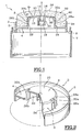
- FIG. 2 is a perspective view, with partial section, of the support of FIG. 1.
- Figure 3 is an axial section of an application assembly comprising the support of Figure 2 after attachment to the tank.
- Figures 4 to 6 illustrate a second embodiment of an application assembly according to the invention.
- Figure 4 is a perspective view, partly in section, of a support.
- Figure 5 is an axial section of the support of Figure 4 provided with an applicator member, before attachment to a reservoir.
- Figure 6 is an axial section of an application assembly comprising the support of Figure 4 after attachment to the tank.
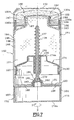
- Figure 7 is an axial section of an application assembly according to a third variant of the invention.
- Figures 8 and 9 illustrate a fourth embodiment of an application assembly according to the invention.
- Figure 8 is a perspective view, partly in section, of a support.
- Figure 9 is an axial section of the support provided with an applicator member.
- a support 2 carrying an applicator member 32 The support 2 is provided with an annular groove 4 delimited by a peripheral ring 5 and a wall 8 coaxial.
- This support 2 also comprises a plate 6 carried by the wall 8.
- This wall 8 is in the form of a cylinder centered along an axis X.
- the plate 6 has an upper face 10 and a lower face 12, as well as an orifice 14 centered along the axis X.
- This plate 8 is provided on the lower face 12 with a central hollow endpiece 16 comprising an internal envelope 18 and an external envelope 20.
- the wall 8 has an internal surface 22 and an external surface 24. As best seen in FIG. 2, the wall 8 also includes tabs 26a, 26b located in longitudinal openings 28a, 28b formed in the wall 8. Each tab 26a, 26b is elastically deformable in a direction perpendicular to the axis X and has, on the side of the external surface 24 of the wall 8, a protuberance 30a, 30b in the form of a harpoon. In Figures 1 to 3, we see two tabs arranged diametrically.
- the support 2 is connected by its peripheral ring 5 to a cylindrical hoop 7 intended to be fixed to a reservoir 42 (FIG. 3), the connection being made by deformable strips 9, flexible.
- This connection allows flexible actuation of the applicator member 32 and provides a feeling of comfort to the user.
- the applicator member 32 is a porous dome made of sintered material provided with an upper application surface 34, slightly curved, convex towards the outside and a lower surface 36 in contact with the upper face 10 of the plate 6.
- the dome 32 also includes an annular part 38, integral with the application surface 34 and housed in the annular groove 4 of the support 2 and has an internal attachment surface 40 in the form of a cylinder centered along the axis X.
- the attachment surface 40 has a shape complementary to that of the external surface 24 of the wall 8 and matching the shape of this external surface 24.
- the attachment surface 40 pushes the tongues 26a, 26b radially in a direction substantially perpendicular to the axis X and directed towards this axis.
- an application assembly designated as a whole by the reference 1 symmetrical along the axis X and comprising a reservoir 42, generally cylindrical, pressurized using a propellant.
- This reservoir 42 carries at its upper end a valve cup 44 fixed to the reservoir by a crimping bead 48.
- the valve cup 44 carries, along the axis X, the distribution valve 46 which, in the case of the present example , is a male valve comprising an emerging hollow rod 50.
- This valve is a valve with lateral deformation, also called “tilt" valve, the opening of which is effected by lateral tilting of the rod 50, or a valve with axial depression.
- the reservoir also contains a liquid or pasty product to be dispensed, for example a cosmetic product such as a deodorant, perfuming, depilatory or slimming product.
- a cosmetic product such as a deodorant, perfuming, depilatory or slimming product.
- the end 52 of the hollow rod 50 serves as an outlet for the product contained in the reservoir 42. It is understood that the pressurized reservoir 42 could be replaced by a flexible tube actuated manually.
- a part 54 of cylindrical shape is placed between the support 2 and the reservoir 42.
- This part 54 comprises a first internal skirt 56 and a second skirt 58 provided with a surface external 60, these skirts 56 and 58 being coaxial and linked to a base 62, in the form of a disc, situated in a plane substantially perpendicular to the axis X.
- the external surface 60 has a cylindrical shape centered along the axis X complementary to the internal surface 22 of the wall 8 and presses on said surface 22.
- the part 54 is fixed to the support 2 by tightening on the external casing 20 of the end piece 16.
- the external surface 60 of the second skirt 58 is then in contact with the internal surface 22 of the wall 8 and prevents any deformation of the tongues 26a, 26b.
- the harpoons 30a, 30b of these tabs are pressed into the attachment surface 40 of the porous dome 32 holding the latter in a fixed position in the support 2.
- the hoop 7 is then fixed on the reservoir 42 and the free end 52 of the valve stem 50 is forcibly engaged in the nozzle 16 of the support 2.
- the support 2 could be fixed directly on the valve stem 50 without the hoop.
- the user exerts pressure or presses on the upper application surface 34 of the porous dome 32.
- the porous dome 32 rocks or sinks (depending on the type of valve used ) and causes, by tilting or depression of the valve stem 50 46, the opening of the valve.
- the product passes through the orifice 14 of the support 2 then diffuses into the porous dome 32 and spreads over its upper surface 34. The product is then applied to the surface to be treated.
- the dome 32 held by the fixing means of the invention remains securely fixed in the support 2 despite the variations in volume of the dome which may occur during the use of the application assembly.
- FIGS. 4 to 6 the elements identical or playing roles analogous to the elements already described are designated by the same reference numerals. Their description will not be repeated or will be made succinctly.
- Figures 4 to 6 show a support 2 which differs from that of Figure 2 in that the tabs 26a, 26b are held in the dome holding position 32 by fixing the endpiece 16 on the free end 52 valve stem 50.
- the endpiece 16 is elastically deformable in a direction perpendicular to the axis X and is connected to the upper end of each tongue 26a, 26b by a strip 64a, 64b elastically deformable.
- the strip is cut in the plate 6 of the support, in the extension of the windows 28a, 28b of the wall 8.
- the attachment surface 40 of the dome 32 is supported on the protuberances 30a, 30b and pushes the tabs 26a, 26b in one direction directed towards the X axis (arrow f).
- This displacement of the tongues 26a, 26b generates the displacement of the strips 64a, 64b in the same direction, then causing deformation (compression) of the endpiece 16.
- the free end 52 of the valve stem 50 When the free end 52 of the valve stem 50 is forcibly engaged in the nozzle 16, as shown in FIG. 6, the latter undergoes deformation in a direction substantially perpendicular and moving away from the axis X ( arrow f '). This deformation of the endpiece 16 also generates the deformation of the strips 64a, 64b, causing the radial displacement of the tongues 26a, 26b. The harpoons 30a, 30b of these tongues are then pressed into the attachment surface 40 of the porous dome 32. The endpiece 16 is permanently fixed on the free end 52 of the valve stem 50, the strips 64a, 64b and the tongues 26a, 26b can no longer deform and the dome 32 is held in a fixed position in the support 2.
- the reservoir 142 comprises a cylindrical body 166 having a longitudinal axis X and containing the product which is preferably of thick consistency, such as a deodorant gel.
- the section of the body 166 perpendicular to the X axis can be circular or oval.
- the cylindrical body 166 comprises at one of its ends a neck 167 provided with a dispensing head 168.
- This head 168 comprises a porous dome 132 carried by a support 102 as illustrated in FIG. 2.
- the dome 132 is in communication with the product outlet from the reservoir 142, that is to say with the end of the neck 167 carrying the dispensing head 168.
- the neck 167 has an external surface 169 of cylindrical shape centered along the axis X complementary to the internal surface 122 of the wall 108 of the support 102.
- the neck 167 is connected to a skirt 194 by a cylindrical shoulder 193, the lower end 195 of the skirt 194 being fixed to the upper edge 196 of the body 166.
- the external surface 169 of the neck 167 is then in abutment with the internal surface 122 of the wall 108 and prevents any deformation of the tongues 126a, 126b.
- the harpoons 130a, 130b of these tongues are pressed into the attachment surface 140 of the porous dome 132, maintaining the latter in a fixed position in the support 102.
- the dispensing head 168 is capped with a cover 170 which is fixed to an annular flange 171 of the skirt 194.
- the second end of the body 166 opposite the dispensing head 168, comprises an actuating element 172 in the form of an elongated handle, of same section as that of the body 166, this handle being pivotally mounted around the axis X of the assembly.
- the side wall 173 of the actuating element 172 acts as a gripping surface which is accessible over the entire periphery of the element 172. A user can thus grasp the element 172 and rotate it around the axis X, as symbolized in Figure 7 by the arrow F.
- the body 166 internally comprises a piston 174 whose section corresponds precisely to the internal section of the body 166.
- This piston 174 has at its center a threaded orifice 175, crossed by a rod 177 provided with a thread 178 and d 'a frustoconical base 179 provided with an annular groove 182.
- This rod 177 is mounted freely in rotation about the axis X of the assembly, while being immobilized axially.
- the bottom 181 of the body comprises a rim 180 in annular projection, which cooperates with the annular groove 182 of the frustoconical base 179, formed in a skirt 183 secured to the bottom 181, the skirt 183 being directed towards the reservoir.
- the skirt 183 has a shape adapted to receive the frustoconical base 179 of the rod 177 and ensures the axial maintenance of the rod 177.
- the rim 180 is surrounded by an elastic cuff 185, to seal the interior of the reservoir 142 vis-à-vis the exterior, thus preventing any penetration of ambient air which could cause drying or degradation. of the packaged product.
- the base 179 of the rod 177 is integral with the actuating element 172.
- this base is connected to a plate 186 extended laterally by a cylindrical skirt 187 which is connected to the side wall 173 of the element d actuation 172 by a shoulder groove system 184.
- the end of the element 172, opposite the base 179, is closed by a plate 172a.
- the flat part 181a of the bottom 181 and the plate 186 are provided with boss systems 188 / hollow part 189, arranged one opposite the other and cooperating with each other, this system allowing the user to reposition the actuating element 172 in the extension of the body 166.
- the piston 174 has an upper face 174a in contact with the product to be dispensed and whose shape is complementary to that of the shoulder 193 of the reservoir.
- the piston 174 also includes at its periphery sealing lips 190 which bear strongly against the internal lateral wall of the body 166, and ensure perfect sealing between the volume 191 of the reservoir, containing the product to be dispensed and the volume 192 defined between the piston 174 and the bottom 181.
- the user removes the cover 170 from the reservoir and then rotates the actuating element 172 according to the arrow F.
- the rotation of this element 172 induces the rotation of the rod 177 and generates a displacement axial of the piston 174, which has the effect of pushing the product through the dome 132.
- the product can then be applied to the surface to be treated.
- FIGs 8 and 9 there is shown an alternative embodiment according to the invention. The differences relate to the elastically deformable fixing means.
- the upper end 9 of the wall 8 has tabs 27a, 27b, 27c in the form of rod whose axis is slightly inclined relative to the axis X of the support.
- Each tongue 27a, 27b, 27c comprises a free end 29a, 29b, 29c, the second end 31a, 31b, 31c of each tongue being fixed to the support 2.
- the attachment surface 40 pushes the tongues 27a, 27b, 27c towards the annular groove 4.
- the tongues 27a, 27b are then folded and arranged between the wall 8 and the attachment surface 40.
- the tongues 27a, 27b being elastically deformable, they exert a radial force on the attachment surface 40 and thus maintain the application member 32 on the support 2.
- the free end 29a, 29b enters the attachment surface 40. If the application member tends to detach from the support, the tabs 27a, 27b are braced and then prevent the application member 32 to separate from the support 2.
- the retention of the dome 32 on the support can be further improved by shaping the free ends 29a, 29b of the tongues 27a, 27b in the shape of a point. These pointed ends 29a, 29b then penetrate more easily into the attachment surface 40 of the dome 32, keeping the latter even more securely on the support 2.
Landscapes
- Engineering & Computer Science (AREA)
- Mechanical Engineering (AREA)
- Containers And Packaging Bodies Having A Special Means To Remove Contents (AREA)
- Closures For Containers (AREA)
- Coating Apparatus (AREA)
- Supports For Pipes And Cables (AREA)
Abstract
Description
- L'invention est relative à un ensemble d'application d'un produit fluide ou solide sur une surface à traiter. L'ensemble d'application peut notamment être utilisé dans le domaine cosmétique pour l'application d'un déodorant, dans le domaine pharmaceutique pour l'application de répulsifs pour insectes, ainsi que dans les domaines des colles, des peintures ou des cirages.
- Plus spécialement, cet ensemble d'application est destiné à l'application d'un déodorant corporel.
- Le document FR-A-2 713 060, au nom de la demanderesse, décrit un ensemble d'application comprenant un réservoir de produit sous pression, muni d'une valve de distribution et d'un organe d'application comportant un dôme poreux, fixé sur le réservoir. Ce dôme est maintenu par un support lié mécaniquement à une frette fixée sur le réservoir. Lors de l'application de cet ensemble sur la surface à traiter, le dôme poreux s'imbibe de produit. Cependant, le produit imbibé dans le dôme peut engendrer une modification du volume du dôme et notamment une réduction de celui-ci. Cette variation du volume peut provoquer une diminution du maintien du dôme sur le support. Aussi, après un certain temps d'utilisation de l'applicateur, le dôme peut se détacher du support et tomber. L'applicateur n'est alors plus utilisable et il n'est pas possible se replacer le dôme sur le support.
- La présente invention vise donc à remédier aux inconvénients mentionnés ci-dessus.
- La présente invention a pour but, surtout, de proposer un ensemble d'application qui évite la séparation du dôme du support. Il a pour but notamment de renforcer le maintien du dôme sur le support.
- La présente invention a donc pour objet un ensemble d'application d'un produit comprenant un réservoir du produit à distribuer, muni d'une sortie pour le produit, un organe d'application du produit en communication avec le réservoir, présentant une surface externe d'application et porté par un support fixé sur la sortie de produit du réservoir, caractérisé par le fait que le support comporte des moyens de fixation élastiquement déformables aptes à maintenir fixe l'organe d'application sur le support.
- Selon un premier mode de réalisation lesdits moyens de fixation élastiquement déformables sont bloqués en position de maintien de l'organe d'application lors de la fixation du support sur la sortie de produit.
- De façon avantageuse, les moyens de fixation sont élastiquement déformables selon une direction sensiblement perpendiculaire à un axe de symétrie (X) du réservoir. De préférence, ces moyens de fixation exercent une force radiale sur l'organe d'application.
- Selon l'invention, l'organe d'application peut comporter avantageusement au moins une surface d'accrochage dans laquelle viennent se fixer les moyens de fixation élastiquement déformables. De préférence, la surface d'accrochage se présente sous la forme d'un cylindre disposé sensiblement selon l'axe X et centré sur cet axe, de façon à permettre une répartition régulière des moyens de fixation fixés dans la surface d'accrochage.
- Les moyens de fixation élastiquement déformables permettent de remettre en place l'organe d'application lorsque celui-ci se détache du support. Il est également possible de changer à volonté l'organe d'application. Ainsi, l'ensemble d'application selon l'invention comporte un organe d'application interchangeable.
- Selon un second mode de réalisation selon l'invention, les moyens de fixation élastiquement déformables sont bloqués en position de maintien de l'organe d'application avant la fixation du support sur la sortie de produit.
- Avantageusement, l'ensemble d'application comprend une jupe en appui radial sur les moyens de fixation, permettant un bon blocage de ceux-ci en position de maintien.
- En outre, pour assurer une bonne fixation de l'organe d'application, le support peut comprendre une paroi munie d'une surface interne et d'une surface externe de forme complémentaire à la surface d'accrochage de l'organe d'application et comportant les moyens de fixation élastiquement déformables.
- Comme moyens de fixation élastiquement déformables, on peut utiliser des languettes souples munies de moyens d'accrochage dont la forme peut être aisément moulée lors de la fabrication du support. Par exemple, les moyens d'accrochage peuvent comprendre au moins un harpon. Ils pourraient être un simple crochet ou un élément en saillie radiale, notamment une protubérance.
- Selon le premier mode de réalisation, les moyens de fixation élastiquement déformables peuvent être bloqués en position de maintien à l'aide d'une pièce placée entre le support et le récipient. Cette pièce peut comprendre une jupe ayant une surface externe complémentaire de la surface interne de la paroi du support et appuyant radialement sur ladite surface interne de la paroi. L'appui radial de la jupe empêche la déformation des moyens de fixation élastiquement déformables lorsque le support est fixé sur la sortie de produit.
- En particulier, lorsque les moyens de fixations sont élastiquement déformables selon une direction sensiblement perpendiculaire à l'axe X, la pièce empêche toute déformation de ces moyens de fixation selon cette direction perpendiculaire.
- Selon ce mode de réalisation, le blocage en position de maintien des moyens de fixation élastiquement déformables est réalisé avant de fixer le support sur la sortie de produit du réservoir.
- Avantageusement, la pièce peut comporter une première jupe et une deuxième jupe pouvant se présenter sous forme de cylindres coaxiaux disposés sensiblement selon l'axe X et centrés sur cet axe. En particulier, la première jupe peut être fixée, notamment par serrage, sur un embout du support, l'embout étant fixé sur la sortie de produit du réservoir. La deuxième jupe comporte de préférence une surface externe complémentaire de la surface interne de la paroi du support, de sorte que les moyens de fixation soient bien bloqués en position de maintien.
- Selon un troisième mode de réalisation selon l'invention, les moyens de fixation élastiquement déformables sont bloqués en position de maintien de l'organe d'application lors de la fixation du support sur la sortie de produit.
- Selon ce deuxième mode de réalisation, le support comporte un embout déformable relié aux moyens de fixation élastiquement déformables par un moyen de liaison déformable, l'ensemble formé par l'embout, le moyen de liaison et les moyens de fixation étant bloqués en position de maintien lors de la fixation de l'embout sur la sortie de produit du réservoir.
- Avantageusement, le moyen de liaison déformable est en forme de bande. Cette bande est de préférence comprise dans un plan sensiblement perpendiculaire à l'axe X, de façon à coopérer avec l'élasticité des moyens de fixation selon une direction sensiblement perpendiculaire à l'axe X.
- Ainsi, lorsque l'embout est fixé sur la sortie de produit, il se déforme selon une direction sensiblement perpendiculaire à l'axe X, cette déformation est transmise par l'intermédiaire des moyens de liaisons déformables, par exemple ladite bande, aux moyens de fixation et ces derniers sont alors maintenus en position de maintien.
- Par ailleurs, l'ensemble d'application peut comprendre des liens déformables entre le support et une frette fixée sur le réservoir, ce qui permet une manipulation aisée de l'ensemble par l'utilisateur et confère une souplesse de fonctionnement. Ces liens déformables peuvent consister en une ou plusieurs lanières souples réparties régulièrement entre le support et la frette.
- Dans un quatrième mode de réalisation selon l'invention, les moyens de fixation élastiquement déformables peuvent être des languettes pliables. Lorsque l'organe d'application est placé sur le support, les languettes se plient et se fixent dans la surface d'accrochage de l'organe d'application. Dans ce mode de réalisation, les moyens de fixation élastiquement déformables sont bloqués en position de maintien de l'organe d'application lors de la fixation de l'organe d'application sur le support, indépendamment de la fixation du support sur la sortie de produit.
- En outre, le réservoir de l'ensemble selon l'invention peut comprendre des moyens de compression du produit aptes à produire une pression suffisante sur le produit pour le pousser à travers l'organe d'application. Toutefois, le réservoir pourrait être un flacon ou un tube souple actionné manuellement.
- Avantageusement, l'organe d'application peut être réalisé en un matériau rigide ou déformable. Par exemple, l'organe d'application peut être une mousse à cellules ouvertes, une éponge ou mieux un fritté. De préférence, l'organe d'application a la forme d'un dôme ayant une surface d'application, sensiblement convexe ou plane.
- L'ensemble d'application est tout à fait approprié à la distribution d'un déodorant corporel. Aussi, un autre objet de la présente invention est un ensemble applicateur de déodorant corporel constitué d'un ensemble d'application tel que défini précédemment.
- L'invention consiste, mise à part les dispositions exposées ci-dessus, en un certain nombre d'autres dispositions qui seront explicitées ci-après, à propos d'exemple de réalisation décrits en référence aux figures annexées, mais qui ne sont nullement limitatifs.
- Les figures 1 à 3 illustrent un premier mode de réalisation d'un ensemble d'application selon l'invention.
- La figure 1 est une coupe axiale d'un support muni d'un organe d'application, avant fixation sur un réservoir.
- La figure 2 est une vue en perspective, avec coupe partielle, du support de la figure 1.
- La figure 3 est une coupe axiale d'un ensemble d'application comportant le support de la figure 2 après fixation sur le réservoir.
- Les figures 4 à 6 illustrent un second mode de réalisation d'un ensemble d'application selon l'invention.
- La figure 4 est une vue en perspective, avec coupe partielle, d'un support.
- La figure 5 est une coupe axiale du support de la figure 4 muni d'un organe d'application, avant fixation sur un réservoir.
- La figure 6 est une coupe axiale d'un ensemble d'application comportant le support de la figure 4 après fixation sur le réservoir.
- La figure 7 est une coupe axiale d'un ensemble d'application conforme à une troisième variante de l'invention.
- Les figures 8 et 9 illustrent un quatrième mode de réalisation d'un ensemble d'application selon l'invention.
- La figure 8 est une vue en perspective, avec coupe partielle, d'un support.
- La figure 9 est une coupe axiale du support muni d'un organe d'application.
- En se reportant aux figures 1 à 3 annexées, on peut voir un support 2 portant un organe d'application 32. Le support 2 est muni d'une gorge annulaire 4 délimitée par une bague périphérique 5 et d'une paroi 8 coaxiale. Ce support 2 comporte également un plateau 6 porté par la paroi 8. Cette paroi 8 se présente sous forme de cylindre centré selon un axe X. Le plateau 6 comporte une face supérieure 10 et une face inférieure 12, ainsi qu'un orifice 14 centré selon l'axe X. Ce plateau 8 est muni sur la face inférieure 12 d'un embout creux central 16 comprenant une enveloppe interne 18 et une enveloppe externe 20.
- La paroi 8 comporte une surface interne 22 et une surface externe 24. Comme mieux visible sur la figure 2, la paroi 8 comporte également des languettes 26a, 26b situées dans des ouvertures 28a, 28b longitudinales pratiquées dans la paroi 8. Chaque languette 26a, 26b est élastiquement déformable selon une direction perpendiculaire à l'axe X et présente du côté de la surface externe 24 de la paroi 8 une protubérance 30a, 30b en forme de harpon. Sur les figures 1 à 3, on voit deux languettes disposées diamétralement.
- Le support 2 est raccordé par sa bague périphérique 5 à une frette cylindrique 7 destinée à être fixée sur un réservoir 42 (figure 3), le raccordement étant réalisé par des lanières déformables 9, souples. Ce raccordement permet un actionnement souple de l'organe d'application 32 et apporte une sensation de confort à l'utilisateur.
- L'organe d'application 32 est un dôme poreux en matériau fritté muni d'une surface d'application supérieure 34, légèrement bombée, convexe vers l'extérieur et une surface inférieure 36 en contact avec la face supérieure 10 du plateau 6. Le dôme 32 comporte également une partie annulaire 38, solidaire de la surface d'application 34 et logée dans la gorge annulaire 4 du support 2 et présente une surface interne d'accrochage 40 sous forme d'un cylindre centré selon l'axe X. On voit sur la figure 1 que la surface d'accrochage 40 à une forme complémentaire à celle de la surface externe 24 de la paroi 8 et épousant la forme de cette surface externe 24.
- Lorsque le dôme 32 est logé dans la gorge annulaire 4, la surface d'accrochage 40 pousse radialement les languettes 26a, 26b selon un sens sensiblement perpendiculaire à l'axe X et dirigé vers cet axe.
- En se reportant à la figure 3, on peut voir un ensemble d'application désigné dans son ensemble par la référence 1 symétrique selon l'axe X et comportant un réservoir 42, généralement cylindrique, pressurisé à l'aide d'un gaz propulseur. Ce réservoir 42 porte à son extrémité supérieure un coupelle 44 de valve 46 fixée au réservoir par un bourrelet de sertissage 48. La coupelle 44 de valve porte, selon l'axe X, la valve de distribution 46 qui, dans le cas du présent exemple, est une valve mâle comportant une tige creuse émergente 50. Cette valve est une valve à déformation latérale, appelée également valve "tilt", dont l'ouverture s'effectue par basculement latéral de la tige 50, ou une valve à enfoncement axial. Le réservoir contient, en outre, un produit liquide ou pâteux à distribuer, par exemple cosmétique tel qu'un produit déodorant, de parfumage, épilatoire, amincissant. En outre, l'extrémité 52 de la tige creuse 50 sert de sortie pour le produit contenu dans le réservoir 42. Il est bien entendu que le réservoir 42 pressurisé pourrait être remplacé par un tube souple actionné manuellement.
- Avant de fixer le support de la figure 1 sur le réservoir 42, une pièce 54 de forme cylindrique est placée entre le support 2 et le réservoir 42. Cette pièce 54 comporte une première jupe 56 interne et une deuxième jupe 58 munie d'une surface externe 60, ces jupes 56 et 58 étant coaxiales et liées à une embase 62, en forme de disque, située dans un plan sensiblement perpendiculaire à l'axe X. La surface externe 60 a une forme cylindrique centrée selon l'axe X complémentaire de la surface interne 22 de la paroi 8 et appuie sur ladite surface 22.
- La pièce 54 est fixée au support 2 par serrage sur l'enveloppe externe 20 de l'embout 16. La surface externe 60 de la deuxième jupe 58 est alors en contact avec le surface interne 22 de la paroi 8 et empêche toute déformation des languettes 26a, 26b. Les harpons 30a, 30b de ces languettes sont enfoncés dans la surface d'accrochage 40 du dôme poreux 32 maintenant celui-ci en position fixe dans le support 2.
- Après avoir fixé la pièce 54 sur le support 2, la frette 7 est ensuite fixée sur le réservoir 42 et l'extrémité libre 52 de la tige 50 de valve est engagée à force dans l'embout 16 du support 2. Bien entendu, le support 2 pourrait être fixé directement sur la tige 50 de valve sans la frette.
- Pour utiliser l'ensemble d'application de l'invention, l'utilisateur exerce une pression ou appuie sur la surface d'application supérieure 34 du dôme poreux 32. Le dôme poreux 32 bascule ou s'enfonce (selon le type de valve utilisé) et provoque, par basculement ou enfoncement de la tige 50 de valve 46, l'ouverture de la valve. Le produit traverse l'orifice 14 du support 2 puis diffuse alors dans le dôme poreux 32 et se répand sur sa surface supérieure 34. Le produit est alors appliqué sur la surface à traiter.
- Le dôme 32 maintenu par les moyens de fixation de l'invention reste bien fixé dans le support 2 malgré les variations de volume du dôme qui peuvent survenir au cours de l'utilisation de l'ensemble d'application.
- Sur les figures 4 à 6, les éléments identiques ou jouant des rôles analogues aux éléments déjà décrits sont désignés par les mêmes références numériques. Leur description ne sera pas reprise ou sera effectuée succinctement.
- Les figures 4 à 6 montrent un support 2 qui se distingue de celui de la figure 2 par le fait que les languettes 26a, 26b sont maintenues en position de maintien du dôme 32 par la fixation de l'embout 16 sur l'extrémité libre 52 de la tige 50 de valve.
- Dans ce mode de réalisation, l'embout 16 est élastiquement déformable selon une direction perpendiculaire à l'axe X et est relié à l'extrémité supérieure de chaque languette 26a, 26b par une bande 64a, 64b élastiquement déformable. La bande est découpée dans le plateau 6 du support, dans le prolongement des fenêtres 28a, 28b de la paroi 8.
- Lorsque le dôme 32 est placé dans la gorge annulaire 4 du support 2, comme visible sur la figure 5, la surface d'accrochage 40 du dôme 32 est en appui sur les protubérances 30a, 30b et repousse les languettes 26a, 26b selon un sens dirigé vers l'axe X (flèche f). Ce déplacement des languettes 26a, 26b engendre le déplacement des bandes 64a, 64b dans le même sens, provoquant alors une déformation (compression) de l'embout 16.
- Lorsque l'extrémité libre 52 de la tige 50 de valve est engagée à force dans l'embout 16, comme le montre la figure 6, celui-ci subit une déformation dans un sens sensiblement perpendiculaire et s'éloignant de l'axe X (flèche f'). Cette déformation de l'embout 16 engendre également la déformation des bandes 64a, 64b, provoquant le déplacement radial des languettes 26a, 26b. Les harpons 30a,30b de ces languettes sont alors enfoncés dans la surface d'accrochage 40 du dôme poreux 32. L'embout 16 étant fixé de façon permanente sur l'extrémité libre 52 de la tige 50 de valve, les bandes 64a, 64b et les languettes 26a, 26b ne peuvent plus se déformer et le dôme 32 est maintenu en position fixe dans le support 2.
- Sur la figure 7, on a représenté une variante de réalisation de l'invention ; les éléments identiques ou jouant des rôles analogues à des éléments déjà décrits à propos des figures précédentes sont désignés par les mêmes références majorées de cent. Leur description ne sera pas reprise ou sera effectuée succinctement. Les différences portent sur les moyens de compression du produit qui sont de nature mécanique.
- Ainsi, le réservoir 142 comprend un corps cylindrique 166 ayant un axe longitudinal X et contenant le produit qui est de préférence de consistance épaisse, tel qu'un gel déodorant. La section du corps 166 perpendiculaire à l'axe X peut être circulaire ou ovale. Le corps cylindrique 166 comporte à une de ses extrémités un col 167 muni d'une tête de distribution 168. Cette tête 168 comprend un dôme poreux 132 porté par un support 102 tel qu'illustré à la figure 2. Le dôme 132 est en communication avec la sortie de produit du réservoir 142, c'est-à-dire avec l'extrémité du col 167 portant la tête de distribution 168.
- Le col 167 présente une surface externe 169 de forme cylindrique centrée selon l'axe X complémentaire de la surface interne 122 de la paroi 108 du support 102. Le col 167 est relié à une jupe 194 par un épaulement cylindrique 193, l'extrémité inférieure 195 de la jupe 194 étant fixée au bord supérieur 196 du corps 166. Lorsque le support 102 est fixé par serrage sur le col 167 du réservoir 142, la surface externe 169 du col 167 est alors en appui avec la surface interne 122 de la paroi 108 et empêche toute déformation des languettes 126a, 126 b. Les harpons 130a, 130b de ces languettes sont enfoncés dans la surface d'accrochage 140 du dôme poreux 132, maintenant celui-ci en position fixe dans le support 102.
- La tête de distribution 168 est coiffée d'un capot 170 qui est fixé sur un rebord annulaire 171 de la jupe 194.
- La deuxième extrémité du corps 166, opposée à la tête de distribution 168, comporte un élément d'actionnement 172 en forme de poignée allongée, de même section que celle du corps 166, cette poignée étant montée pivotante autour de l'axe X de l'ensemble.
- La paroi latérale 173 de l'élément d'actionnement 172 joue le rôle de surface de préhension qui est accessible sur toute la périphérie de l'élément 172. Un utilisateur peut ainsi saisir l'élément 172 et le faire pivoter autour de l'axe X, comme symbolisé sur la figure 7 par la flèche F.
- En outre, le corps 166 comporte intérieurement un piston 174 dont la section correspond précisément à la section interne du corps 166. Ce piston 174 comporte en son centre un orifice 175 taraudé 176, traversé par une tige 177 munie d'un filetage 178 et d'une embase tronconique 179 munie d'une gorge annulaire 182. Cette tige 177 est montée librement en rotation autour de l'axe X de l'ensemble, tout en étant immobilisée axialement. A cet effet, le fond 181 du corps comporte
un rebord 180 en saillie annulaire, qui coopère avec la gorge annulaire 182 de l'embase tronconique 179, pratiqué dans une jupe 183 solidaire du fond 181, la jupe 183 étant dirigée vers le réservoir. La jupe 183 présente une forme adaptée pour recevoir l'embase tronconique 179 de la tige 177 et assure le maintien axial de la tige 177. - Le rebord 180 est entouré d'une manchette élastique 185, pour assurer l'étanchéité de l'intérieur du réservoir 142 vis-à-vis de l'extérieur, empêchant ainsi toute pénétration d'air ambiant qui pourrait entraîner le dessèchement ou la dégradation du produit conditionné.
- L'embase 179 de la tige 177 est solidaire de l'élément d'actionnement 172. En effet, cette embase se raccorde à un plateau 186 prolongé latéralement par une jupe cylindrique 187 qui se raccorde à la paroi 173 latérale de l'élément d'actionnement 172 par un système gorge épaulement 184. L'extrémité de l'élément 172, opposé à l'embase 179, est fermé par un plateau 172a.
- La partie plane 181a du fond 181 et le plateau 186 sont pourvus de systèmes bossage 188/ partie en creux 189, disposés l'un en vis-à-vis de l'autre et coopérant l'un avec l'autre, ce système permettant à l'utilisateur de repositionner l'élément d'actionnement 172 dans le prolongement du corps 166.
- En outre, le piston 174 présente une face supérieure 174a en contact avec le produit à distribuer et dont la forme est complémentaire de celle de l'épaulement 193 du réservoir. Le piston 174 comporte également à sa périphérie des lèvres d'étanchéité 190 qui s'appuient fortement contre la paroi latérale interne du corps 166, et assurent une étanchéité parfaite entre le volume 191 du réservoir, contenant le produit à distribuer et le volume 192 défini entre le piston 174 et le fond 181.
- Pour utiliser l'ensemble d'application, l'utilisateur retire le capot 170 du réservoir puis fait pivoter l'élément d'actionnement 172 selon la flèche F. La rotation de cet élément 172 induit la rotation de la tige 177 et génère un déplacement axial du piston 174, ce qui a pour effet de pousser le produit à travers le dôme 132. Le produit peut alors être appliqué sur la surface à traiter.
- Sur les figures 8 et 9, on a représenté une variante de réalisation selon l'invention. Les différences portent sur les moyens de fixation élastiquement déformables.
En se reportant à la figure 8, on peut voir que l'extrémité supérieure 9 de la paroi 8 comporte des languettes 27a, 27b, 27c en forme de tige dont l'axe est légèrement incliné par rapport à l'axe X du support. Chaque languette 27a, 27b, 27c comprend une extrémité libre 29a, 29b, 29c, la deuxième extrémité 31a, 31b, 31c de chaque languette étant fixée au support 2. - Lorsque le dôme 32 est logé dans la gorge annulaire 4, la surface d'accrochage 40 pousse les languettes 27a, 27b, 27c vers la gorge annulaire 4. Comme visible sur la figure 9, les languettes 27a, 27b sont alors pliées et disposées entre la paroi 8 et la surface d'accrochage 40. Les languettes 27a, 27b étant élastiquement déformables, elles exercent une force radiale sur la surface d'accrochage 40 et maintiennent ainsi l'organe d'application 32 sur le support 2. De plus, l'extrémité libre 29a, 29b pénètre dans la surface d'accrochage 40. Si l'organe d'application a tendance à se détacher du support, les languettes 27a, 27b s'arc-boutent et empêchent alors l'organe d'application 32 de se séparer du support 2. Le maintien du dôme 32 sur le support peut être encore amélioré en conformant les extrémités libres 29a, 29b des languettes 27a, 27b en forme de pointe. Ces extrémités pointues 29a, 29b pénètrent alors plus facilement dans la surface d'accrochage 40 du dôme 32, maintenant de façon encore plus sûre ce dernier sur le support 2.
Claims (25)
- Ensemble d'application d'un produit comprenant un réservoir (42, 142) renfermant un produit à distribuer et muni d'une sortie (52, 167) pour le produit, un organe d'application (32, 132) du produit en communication avec le réservoir, présentant une surface externe (34) d'application et porté par un support (2, 102) fixé sur la sortie de produit du réservoir, caractérisé par le fait que le support comporte des moyens de fixation élastiquement déformables (27a, 27b, 27c, 30a, 30 b, 130a, 130b) aptes à maintenir fixe l'organe d'application dans le support.
- Ensemble d'application selon la revendication 1, caractérisé par le fait que les moyens de fixation sont élastiquement déformables selon une direction sensiblement perpendiculaire à l'axe (X).
- Ensemble d'application selon l'une des revendications 1 et 2, caractérisé par le fait que l'organe d'application comporte au moins une surface d'accrochage (40, 140) dans laquelle viennent se fixer les moyens de fixation élastiquement déformables.
- Ensemble d'application selon la revendication 3, caractérisé par le fait que le support comprend une paroi (8, 108) munie d'une surface externe (24) et d'une surface interne (22, 122), la surface externe étant complémentaire de la surface d'accrochage de l'organe d'application et comportant les moyens de fixation élastiquement déformables.
- Ensemble d'application selon l'une des revendications 3 et 4, caractérisé par le fait que la surface d'accrochage est en forme de cylindre centré selon l'axe X.
- Ensemble d'application selon l'une quelconque des revendications précédentes, caractérisé par le fait que les moyens de fixation élastiquement déformables sont des languettes (27a, 27b, 26a, 26b, 126a, 126b) souples munies de moyens d'accrochage.
- Ensemble d'application selon la revendication 5, caractérisé par le fait que les moyens d'accrochage comprennent au moins un harpon (30a, 30b, 130a, 130b).
- Ensemble d'application selon l'une quelconque des revendications précédentes, caractérisé par le fait que les moyens de fixation élastiquement déformables sont bloqués en position de maintien avant la fixation ou lors de la fixation du support sur la sortie de produit du réservoir.
- Ensemble d'application selon l'une quelconque des revendications précédentes, caractérisé par le fait que les moyens de fixation élastiquement déformables sont bloqués à l'aide d'une pièce (54, 167) placée entre le support et le réservoir.
- Ensemble d'application selon la revendication 9, caractérisé par le fait que la pièce comprend une jupe (58) ayant une surface externe (60) complémentaire de la surface interne de la paroi du support et appuyant radialement sur ladite surface interne.
- Ensemble d'application selon l'une des revendications 9 et 10, caractérisé par le fait que la pièce comporte une première jupe (56) et une deuxième jupe (58), la première jupe étant fixée sur un embout (16) du support, l'embout étant fixé sur la sortie de produit du réservoir, et la deuxième jupe ayant une surface externe (60) complémentaire de la surface interne de la paroi du support.
- Ensemble d'application selon l'une quelconque des revendications 1 à 8, caractérisé par le fait que le support comporte un embout (16) déformable relié aux moyens de fixation élastiquement déformables par un moyen de liaison déformable (64a, 64b), l'ensemble formé par l'embout, le moyen de liaison et les moyens de fixation étant bloqués en position lors de la fixation de l'embout sur la sortie de produit du réservoir.
- Ensemble d'application selon la revendication 12, caractérisé par le fait que le moyen de liaison déformable est en forme de bande (64a, 64b).
- Ensemble d'application selon la revendication 11, caractérisé par le fait que la bande est comprise dans un plan sensiblement perpendiculaire à l'axe X.
- Ensemble d'application selon la revendication 9, caractérisé par le fait que la pièce est un col (167) du réservoir et que les moyens de fixation élastiquement déformables sont bloqués par le col.
- Ensemble d'application selon l'une quelconque des revendications 1 à 7, caractérisée par le fait que les moyens de fixation élastiquement déformables sont des languettes pliables (27a, 27b).
- Ensemble d'application selon la revendication 16, caractérisé par le fait que les languettes (27a, 27b) sont pliées lorsque l'organe d'application est fixé sur le support et maintiennent l'organe d'application sur le support.
- Ensemble d'application selon l'une quelconque des revendications précédentes, caractérisé par le fait qu'il comporte au moins un lien déformable (9) entre l'organe d'application et une frette (7) fixée sur le réservoir.
- Ensemble d'application selon l'une quelconque des revendications précédentes, caractérisé par le fait qu'il comprend des moyens de compression du produit aptes à produire une pression suffisante sur le produit pour le pousser à travers l'organe d'application.
- Ensemble d'application selon la revendication 19, caractérisé par le fait que les moyens de compression comportent un piston (174) associé à un moyen de manoeuvre (172, 177) du piston.
- Ensemble d'application selon la revendication 20, caractérisé par le fait que le moyen de manoeuvre comprend une tige (177) munie d'un filetage (178) solidaire d'un élément d'actionnement (172), le filetage de la tige coopérant avec un filetage complémentaire (176) du piston.
- Ensemble d'application selon la revendication 20, caractérisé par le fait que les moyens de compression comportent un gaz propulseur et une valve (46) de distribution munie d'une tige creuse (50) coopérant avec l'organe d'application.
- Ensemble d'application selon l'une quelconque des revendications précédentes, caractérisé par le fait que l'organe d'application est un fritté.
- Ensemble d'application selon l'une quelconque des revendications précédentes, caractérisé par le fait que l'organe d'application est un dôme poreux.
- Ensemble applicateur d'un déodorant corporel, caractérisé par le fait qu'il consiste en un ensemble d'application selon l'une quelconque des revendications précédentes.
Applications Claiming Priority (2)
| Application Number | Priority Date | Filing Date | Title |
|---|---|---|---|
| FR9603541A FR2746270B1 (fr) | 1996-03-21 | 1996-03-21 | Ensemble d'application d'un produit fluide ou solide |
| FR9603541 | 1996-03-21 |
Publications (2)
| Publication Number | Publication Date |
|---|---|
| EP0797940A1 true EP0797940A1 (fr) | 1997-10-01 |
| EP0797940B1 EP0797940B1 (fr) | 1999-02-17 |
Family
ID=9490405
Family Applications (1)
| Application Number | Title | Priority Date | Filing Date |
|---|---|---|---|
| EP97400616A Expired - Lifetime EP0797940B1 (fr) | 1996-03-21 | 1997-03-19 | Ensemble d'application d'un produit fluide ou pâteux |
Country Status (9)
| Country | Link |
|---|---|
| US (1) | US5967685A (fr) |
| EP (1) | EP0797940B1 (fr) |
| JP (2) | JP3105927B2 (fr) |
| CN (1) | CN1193262A (fr) |
| BR (1) | BR9707151A (fr) |
| DE (1) | DE69700116T2 (fr) |
| ES (1) | ES2130000T3 (fr) |
| FR (1) | FR2746270B1 (fr) |
| WO (1) | WO1997034512A1 (fr) |
Cited By (3)
| Publication number | Priority date | Publication date | Assignee | Title |
|---|---|---|---|---|
| DE19853253A1 (de) * | 1998-11-18 | 2000-05-25 | Beiersdorf Ag | Vorrichtung zum Auftragen flüssiger Medien auf die Haut |
| WO2003029098A1 (fr) * | 2001-10-01 | 2003-04-10 | L'oreal | Dispositif comportant un element poreux, alveolaire ou fibreux fixe sur un support |
| WO2019092271A1 (fr) * | 2017-11-13 | 2019-05-16 | L'oreal | Tête d'application et de distribution de produit cosmétique, et dispositif d'emballage associé |
Families Citing this family (24)
| Publication number | Priority date | Publication date | Assignee | Title |
|---|---|---|---|---|
| US6428234B1 (en) * | 2000-01-07 | 2002-08-06 | Closure Medical Corporation | Adhesive applicator tips with improved flow properties |
| FR2816285B1 (fr) * | 2000-11-07 | 2003-04-18 | Oreal | Dispositif de conditionnement comportant une unite amovible |
| US6592282B2 (en) | 2000-12-11 | 2003-07-15 | Revlon Consumer Products Corporation | Cosmetic applicator for fluid material |
| FR2832297B1 (fr) * | 2001-11-19 | 2004-08-06 | Oreal | Ensemble de conditionnement et d'application d'un produit |
| JP3735100B2 (ja) * | 2002-07-09 | 2006-01-11 | 株式会社トキワ | 移動体繰出装置 |
| DE20302008U1 (de) | 2003-02-08 | 2003-04-10 | h & m gutberlet gmbh, 90471 Nürnberg | Applikationsvorrichtung zum Auftragen eines flüssigen, gelartigen oder pastösen Kosmetikmediums auf die Haut |
| US7381005B2 (en) * | 2003-06-30 | 2008-06-03 | The Procter And Gamble Company | Pressurized dispensing package and method for using the same |
| FR2860770B1 (fr) * | 2003-10-13 | 2006-08-04 | Oreal | Dispositif de conditionnement et d'application. |
| US20050135867A1 (en) * | 2003-10-13 | 2005-06-23 | Gueret Jean-Louis H. | Substance packaging and applicator device |
| US20070086833A1 (en) * | 2005-10-19 | 2007-04-19 | Paul Gurrisi | Dispenser for personal care composition |
| US7771135B2 (en) * | 2006-03-23 | 2010-08-10 | The Libman Company | Scrubber and cleaning fluid dispenser assembly |
| JP5118734B2 (ja) * | 2010-06-07 | 2013-01-16 | 株式会社トキワ | 化粧料容器 |
| CN103562093B (zh) * | 2011-05-23 | 2016-08-24 | 东兴药品工业株式会社 | 涂布容器 |
| JP5766539B2 (ja) * | 2011-07-28 | 2015-08-19 | 株式会社吉野工業所 | 容器用の注出補助具 |
| KR101893132B1 (ko) * | 2011-11-16 | 2018-08-31 | 주식회사 대유위니아 | 서랍 자동닫힘 냉장고 |
| DE102012211885A1 (de) * | 2012-07-06 | 2014-01-09 | Tetiana Nowack | Applikator zum Auftragen eines flüssigen Mediums, insbesondere im kosmetischen Bereich |
| KR101608179B1 (ko) | 2015-11-24 | 2016-03-31 | 지승구 | 피부용 약물주입장치 |
| FR3047648B1 (fr) * | 2016-02-12 | 2018-02-02 | Chanel Parfums Beaute | Distributeur compressible d'un produit fluide, en particulier un produit fluide cosmetique tel qu'une creme |
| JP6864334B2 (ja) * | 2016-08-18 | 2021-04-28 | 株式会社トキワ | 化粧料塗布容器 |
| FR3058619B1 (fr) * | 2016-11-14 | 2019-07-05 | L'oreal | Applicateur de produit cosmetique liquide |
| JP7411949B2 (ja) * | 2019-08-29 | 2024-01-12 | 東洋エアゾール工業株式会社 | エアゾール容器用アクチュエータ |
| CN110839656A (zh) * | 2019-12-05 | 2020-02-28 | 东莞市普惠森日用品有限公司 | 一种防霉驱虫方法 |
| WO2021133949A1 (fr) * | 2019-12-26 | 2021-07-01 | L'oreal | Système de soupape pour cartouche de formule |
| FR3145556A1 (fr) * | 2023-02-08 | 2024-08-09 | Aptar France Sas | Système de rétention |
Citations (6)
| Publication number | Priority date | Publication date | Assignee | Title |
|---|---|---|---|---|
| US2442503A (en) * | 1946-02-27 | 1948-06-01 | Melnikoff Zachary | Lip rouge applicator |
| EP0037903A1 (fr) * | 1980-03-18 | 1981-10-21 | Lechner + Bek GmbH | Dispositif pour appliquer une substance crémeuse sur une surface |
| US5018894A (en) * | 1989-05-18 | 1991-05-28 | L'oreal | Applicator device for a liquid comprising a dome made of a porous material |
| FR2659941A1 (fr) * | 1990-03-21 | 1991-09-27 | Galletti Renata | Reservoir, en particulier brosse a dents reservoir, avec distribution dosee a piston. |
| US5230579A (en) * | 1991-06-19 | 1993-07-27 | Carter-Wallace, Inc. | Porous dome applicator with push/pull cap |
| FR2713060A1 (fr) * | 1993-11-29 | 1995-06-09 | Oreal | Dispositif applicateur pour liquide. |
Family Cites Families (5)
| Publication number | Priority date | Publication date | Assignee | Title |
|---|---|---|---|---|
| US3137885A (en) * | 1963-03-14 | 1964-06-23 | Jerclaydon Inc | Brush head for dispensing and applying foam detergent |
| US3256549A (en) * | 1964-04-01 | 1966-06-21 | Seaquist Valve Co | Applicator-scrubber |
| US3471245A (en) * | 1967-09-20 | 1969-10-07 | Gilbert Schwartzman | Applicator construction |
| JPH0328954A (ja) * | 1989-06-26 | 1991-02-07 | Nec Corp | コマンドマクロファイル実行装置 |
| ES1028682Y (es) * | 1994-07-28 | 1995-07-01 | Schattaver Schwarzberg Renate | Dispositivo dosificador de liquido para limpieza de gafas y similares perfeccionado. |
-
1996
- 1996-03-21 FR FR9603541A patent/FR2746270B1/fr not_active Expired - Fee Related
- 1996-03-21 US US08/952,519 patent/US5967685A/en not_active Expired - Fee Related
-
1997
- 1997-03-19 BR BR9707151A patent/BR9707151A/pt not_active IP Right Cessation
- 1997-03-19 ES ES97400616T patent/ES2130000T3/es not_active Expired - Lifetime
- 1997-03-19 DE DE69700116T patent/DE69700116T2/de not_active Expired - Fee Related
- 1997-03-19 WO PCT/FR1997/000484 patent/WO1997034512A1/fr active Application Filing
- 1997-03-19 CN CN97190537A patent/CN1193262A/zh active Pending
- 1997-03-19 JP JP09533205A patent/JP3105927B2/ja not_active Expired - Fee Related
- 1997-03-19 EP EP97400616A patent/EP0797940B1/fr not_active Expired - Lifetime
-
1999
- 1999-09-22 JP JP11269463A patent/JP2000085825A/ja active Pending
Patent Citations (6)
| Publication number | Priority date | Publication date | Assignee | Title |
|---|---|---|---|---|
| US2442503A (en) * | 1946-02-27 | 1948-06-01 | Melnikoff Zachary | Lip rouge applicator |
| EP0037903A1 (fr) * | 1980-03-18 | 1981-10-21 | Lechner + Bek GmbH | Dispositif pour appliquer une substance crémeuse sur une surface |
| US5018894A (en) * | 1989-05-18 | 1991-05-28 | L'oreal | Applicator device for a liquid comprising a dome made of a porous material |
| FR2659941A1 (fr) * | 1990-03-21 | 1991-09-27 | Galletti Renata | Reservoir, en particulier brosse a dents reservoir, avec distribution dosee a piston. |
| US5230579A (en) * | 1991-06-19 | 1993-07-27 | Carter-Wallace, Inc. | Porous dome applicator with push/pull cap |
| FR2713060A1 (fr) * | 1993-11-29 | 1995-06-09 | Oreal | Dispositif applicateur pour liquide. |
Cited By (4)
| Publication number | Priority date | Publication date | Assignee | Title |
|---|---|---|---|---|
| DE19853253A1 (de) * | 1998-11-18 | 2000-05-25 | Beiersdorf Ag | Vorrichtung zum Auftragen flüssiger Medien auf die Haut |
| WO2003029098A1 (fr) * | 2001-10-01 | 2003-04-10 | L'oreal | Dispositif comportant un element poreux, alveolaire ou fibreux fixe sur un support |
| WO2019092271A1 (fr) * | 2017-11-13 | 2019-05-16 | L'oreal | Tête d'application et de distribution de produit cosmétique, et dispositif d'emballage associé |
| FR3073373A1 (fr) * | 2017-11-13 | 2019-05-17 | L'oreal | Tete d'application et de distribution de produit cosmetique, et dispositif de conditionnement associe |
Also Published As
| Publication number | Publication date |
|---|---|
| FR2746270A1 (fr) | 1997-09-26 |
| FR2746270B1 (fr) | 1998-10-30 |
| DE69700116T2 (de) | 1999-06-17 |
| WO1997034512A1 (fr) | 1997-09-25 |
| EP0797940B1 (fr) | 1999-02-17 |
| CN1193262A (zh) | 1998-09-16 |
| ES2130000T3 (es) | 1999-06-16 |
| BR9707151A (pt) | 1999-04-06 |
| JPH10507399A (ja) | 1998-07-21 |
| MX9708991A (es) | 1998-03-31 |
| JP3105927B2 (ja) | 2000-11-06 |
| US5967685A (en) | 1999-10-19 |
| JP2000085825A (ja) | 2000-03-28 |
| DE69700116D1 (de) | 1999-03-25 |
Similar Documents
| Publication | Publication Date | Title |
|---|---|---|
| EP0797940B1 (fr) | Ensemble d'application d'un produit fluide ou pâteux | |
| EP0775641B1 (fr) | Ensemble d'application d'un produit fluide ou solide | |
| CA2368052C (fr) | Dispositif pressurise equipe d'une valve a basculement | |
| CA2262135C (fr) | Ensemble de conditionnement et de distribution d'un produit liquide | |
| EP0945368B1 (fr) | Tête pour la distribution et l'application d'un produit, notamment capillaire, et ensemble de conditionnement équipé d'une telle tête | |
| EP0667301B1 (fr) | Dispositif pour distribuer un produit liquide ou pulvérulent | |
| EP0937505B1 (fr) | Ensemble de conditionnement et de distribution, et utilisation d'un tel ensemble pour le conditionnement d'un produit cosmétique, pharmaceutique ou dermopharmaceutique | |
| EP1288142B1 (fr) | Dispositif pour le conditionnement et la distribution sous pression d'un produit | |
| EP0960828B1 (fr) | Organe d'activation d'une valve, valve équipée de cet organe et ensemble de distribution muni de cette valve | |
| FR2711620A1 (fr) | Ensemble de distribution équipé d'un organe de fermeture unidirectionnel. | |
| EP0628355B1 (fr) | Tête pour distributeur de produit, en particulier de produit pâteux, et distributeur équipé de cette tête | |
| CA1175392A (fr) | Ensemble de maquillage comportant un recipient et un applicateur assurant sa fermeture | |
| FR2650255A1 (fr) | Ensemble de distribution d'un ou plusieurs produit(s) sous forme de creme, de liquide ou de poudre, notamment de produits cosmetiques | |
| FR2836902A1 (fr) | Tete de distribution a canule mobile destinee a equiper un dispositif de conditionnement et de distribution | |
| EP0598041A1 (fr) | Valve pour recipient pressurise du type bidon aerosol, et recipient pressurise equipe d'une telle valve. | |
| EP1125517B1 (fr) | Dispositif de conditionnement et d'application comportant un élément formant réservoir intermédiaire | |
| EP0455552A1 (fr) | Dispositif d'actionnement d'une valve de distribution | |
| CH678845A5 (fr) | ||
| FR2814727A1 (fr) | Valve destinee a equiper un dispositif pour la distribution sous pression d'un produit, et dispositif ainsi equipe | |
| CA2182902C (fr) | Ensemble de distribution d'un produit fluide ou solide | |
| FR3080265A1 (fr) | Systeme de fermeture etanche pour un applicateur cosmetique | |
| WO2001053164A2 (fr) | Dispositif d'etancheite pour recipient | |
| EP0184662B1 (fr) | Diffuseur de parfum | |
| FR2650562A1 (fr) | Ensemble de distribution d'un ou plusieurs produit(s) sous forme de creme, de liquide ou de poudre, notamment de produits cosmetiques | |
| FR2714363A1 (fr) | Ensemble de distribution comprenant un récipient cylindrique comportant un piston à deux lèvres. |
Legal Events
| Date | Code | Title | Description |
|---|---|---|---|
| PUAI | Public reference made under article 153(3) epc to a published international application that has entered the european phase |
Free format text: ORIGINAL CODE: 0009012 |
|
| AK | Designated contracting states |
Kind code of ref document: A1 Designated state(s): DE ES FR GB IT |
|
| 17P | Request for examination filed |
Effective date: 19980401 |
|
| 17Q | First examination report despatched |
Effective date: 19980527 |
|
| GRAG | Despatch of communication of intention to grant |
Free format text: ORIGINAL CODE: EPIDOS AGRA |
|
| GRAG | Despatch of communication of intention to grant |
Free format text: ORIGINAL CODE: EPIDOS AGRA |
|
| GRAH | Despatch of communication of intention to grant a patent |
Free format text: ORIGINAL CODE: EPIDOS IGRA |
|
| GRAG | Despatch of communication of intention to grant |
Free format text: ORIGINAL CODE: EPIDOS AGRA |
|
| GRAH | Despatch of communication of intention to grant a patent |
Free format text: ORIGINAL CODE: EPIDOS IGRA |
|
| GRAA | (expected) grant |
Free format text: ORIGINAL CODE: 0009210 |
|
| STAA | Information on the status of an ep patent application or granted ep patent |
Free format text: STATUS: THE PATENT HAS BEEN GRANTED |
|
| AK | Designated contracting states |
Kind code of ref document: B1 Designated state(s): DE ES FR GB IT |
|
| ITF | It: translation for a ep patent filed | ||
| REF | Corresponds to: |
Ref document number: 69700116 Country of ref document: DE Date of ref document: 19990325 |
|
| GBT | Gb: translation of ep patent filed (gb section 77(6)(a)/1977) |
Effective date: 19990428 |
|
| REG | Reference to a national code |
Ref country code: ES Ref legal event code: FG2A Ref document number: 2130000 Country of ref document: ES Kind code of ref document: T3 |
|
| PLBE | No opposition filed within time limit |
Free format text: ORIGINAL CODE: 0009261 |
|
| 26N | No opposition filed | ||
| PGFP | Annual fee paid to national office [announced via postgrant information from national office to epo] |
Ref country code: ES Payment date: 20010228 Year of fee payment: 5 |
|
| PGFP | Annual fee paid to national office [announced via postgrant information from national office to epo] |
Ref country code: DE Payment date: 20010312 Year of fee payment: 5 |
|
| PGFP | Annual fee paid to national office [announced via postgrant information from national office to epo] |
Ref country code: FR Payment date: 20010313 Year of fee payment: 5 |
|
| PGFP | Annual fee paid to national office [announced via postgrant information from national office to epo] |
Ref country code: GB Payment date: 20010314 Year of fee payment: 5 |
|
| REG | Reference to a national code |
Ref country code: GB Ref legal event code: IF02 |
|
| PG25 | Lapsed in a contracting state [announced via postgrant information from national office to epo] |
Ref country code: GB Free format text: LAPSE BECAUSE OF NON-PAYMENT OF DUE FEES Effective date: 20020319 |
|
| PG25 | Lapsed in a contracting state [announced via postgrant information from national office to epo] |
Ref country code: ES Free format text: LAPSE BECAUSE OF NON-PAYMENT OF DUE FEES Effective date: 20020320 |
|
| PG25 | Lapsed in a contracting state [announced via postgrant information from national office to epo] |
Ref country code: DE Free format text: LAPSE BECAUSE OF NON-PAYMENT OF DUE FEES Effective date: 20021001 |
|
| GBPC | Gb: european patent ceased through non-payment of renewal fee |
Effective date: 20020319 |
|
| PG25 | Lapsed in a contracting state [announced via postgrant information from national office to epo] |
Ref country code: FR Free format text: LAPSE BECAUSE OF NON-PAYMENT OF DUE FEES Effective date: 20021129 |
|
| REG | Reference to a national code |
Ref country code: FR Ref legal event code: ST |
|
| REG | Reference to a national code |
Ref country code: ES Ref legal event code: FD2A Effective date: 20030410 |
|
| PG25 | Lapsed in a contracting state [announced via postgrant information from national office to epo] |
Ref country code: IT Free format text: LAPSE BECAUSE OF NON-PAYMENT OF DUE FEES Effective date: 20050319 |