EP0797501B1 - Formwerkzeug für ververbindungsmittel und verbindeverfahren unter verwendung des formwerkzeuges - Google Patents
Formwerkzeug für ververbindungsmittel und verbindeverfahren unter verwendung des formwerkzeuges Download PDFInfo
- Publication number
- EP0797501B1 EP0797501B1 EP95942419A EP95942419A EP0797501B1 EP 0797501 B1 EP0797501 B1 EP 0797501B1 EP 95942419 A EP95942419 A EP 95942419A EP 95942419 A EP95942419 A EP 95942419A EP 0797501 B1 EP0797501 B1 EP 0797501B1
- Authority
- EP
- European Patent Office
- Prior art keywords
- sealant
- molding
- molding tool
- groove
- main body
- Prior art date
- Legal status (The legal status is an assumption and is not a legal conclusion. Google has not performed a legal analysis and makes no representation as to the accuracy of the status listed.)
- Expired - Lifetime
Links
Images


Classifications
-
- B—PERFORMING OPERATIONS; TRANSPORTING
- B29—WORKING OF PLASTICS; WORKING OF SUBSTANCES IN A PLASTIC STATE IN GENERAL
- B29C—SHAPING OR JOINING OF PLASTICS; SHAPING OF MATERIAL IN A PLASTIC STATE, NOT OTHERWISE PROVIDED FOR; AFTER-TREATMENT OF THE SHAPED PRODUCTS, e.g. REPAIRING
- B29C70/00—Shaping composites, i.e. plastics material comprising reinforcements, fillers or preformed parts, e.g. inserts
- B29C70/68—Shaping composites, i.e. plastics material comprising reinforcements, fillers or preformed parts, e.g. inserts by incorporating or moulding on preformed parts, e.g. inserts or layers, e.g. foam blocks
- B29C70/74—Moulding material on a relatively small portion of the preformed part, e.g. outsert moulding
-
- B—PERFORMING OPERATIONS; TRANSPORTING
- B29—WORKING OF PLASTICS; WORKING OF SUBSTANCES IN A PLASTIC STATE IN GENERAL
- B29C—SHAPING OR JOINING OF PLASTICS; SHAPING OF MATERIAL IN A PLASTIC STATE, NOT OTHERWISE PROVIDED FOR; AFTER-TREATMENT OF THE SHAPED PRODUCTS, e.g. REPAIRING
- B29C43/00—Compression moulding, i.e. applying external pressure to flow the moulding material; Apparatus therefor
- B29C43/02—Compression moulding, i.e. applying external pressure to flow the moulding material; Apparatus therefor of articles of definite length, i.e. discrete articles
- B29C43/18—Compression moulding, i.e. applying external pressure to flow the moulding material; Apparatus therefor of articles of definite length, i.e. discrete articles incorporating preformed parts or layers, e.g. compression moulding around inserts or for coating articles
-
- B—PERFORMING OPERATIONS; TRANSPORTING
- B60—VEHICLES IN GENERAL
- B60J—WINDOWS, WINDSCREENS, NON-FIXED ROOFS, DOORS, OR SIMILAR DEVICES FOR VEHICLES; REMOVABLE EXTERNAL PROTECTIVE COVERINGS SPECIALLY ADAPTED FOR VEHICLES
- B60J10/00—Sealing arrangements
- B60J10/30—Sealing arrangements characterised by the fastening means
- B60J10/34—Sealing arrangements characterised by the fastening means using adhesives
-
- B—PERFORMING OPERATIONS; TRANSPORTING
- B60—VEHICLES IN GENERAL
- B60R—VEHICLES, VEHICLE FITTINGS, OR VEHICLE PARTS, NOT OTHERWISE PROVIDED FOR
- B60R13/00—Elements for body-finishing, identifying, or decorating; Arrangements or adaptations for advertising purposes
- B60R13/04—External Ornamental or guard strips; Ornamental inscriptive devices thereon
-
- B—PERFORMING OPERATIONS; TRANSPORTING
- B60—VEHICLES IN GENERAL
- B60R—VEHICLES, VEHICLE FITTINGS, OR VEHICLE PARTS, NOT OTHERWISE PROVIDED FOR
- B60R13/00—Elements for body-finishing, identifying, or decorating; Arrangements or adaptations for advertising purposes
- B60R13/06—Sealing strips
-
- B—PERFORMING OPERATIONS; TRANSPORTING
- B29—WORKING OF PLASTICS; WORKING OF SUBSTANCES IN A PLASTIC STATE IN GENERAL
- B29L—INDEXING SCHEME ASSOCIATED WITH SUBCLASS B29C, RELATING TO PARTICULAR ARTICLES
- B29L2031/00—Other particular articles
- B29L2031/26—Sealing devices, e.g. packaging for pistons or pipe joints
Definitions
- the present invention relates to a molding tool for sealant and a sealing method using the molding tool, whereby an outer surface of the sealant after sealing a jointed part of two members, for instance, a jointed part of exterior panels such as roof panels or the like of an automobile, especially, a jointed part at the bottom of a groove defined when the roof panels are jointed is refined in good shape.
- exterior panels e.g., roof panels of an automobile or the like are jointed by riveting or spot welding or the like manner.
- the exterior panels are usually jointed before an undercoating thereof, and after undercoating, the jointed part is sealed by a sealant for the purpose of prevention of water leakage. Thereafter, the whole of the exterior panel including the jointed part is processed through face coating.
- a jointed part 107 is located at a bottom 106 of a roof groove 105 as indicated in Figs. 11 and 12. The rain or the like is apt to gather in this roof groove 105, and therefore it is required to surely seal the jointed part 107.
- the roof groove 105 referred to above is a groove defined when a stepped part 102 at each side edge of a main roof panel 101 is overlaid and jointed to a stepped part 104 at a side edge of a sub roof panel 103 which is to be jointed to the main roof panel although only one roof groove 105 among the grooves formed at both edges of the main roof panel 101 is represented in Figs. 12 and the other drawings.
- a sealant has been provided at the surface of the jointed part 107 to enhance the sealing properties at the jointed part 107.
- a sealant such type of a sealant is used that is set with heat from the paste-like state, or melted or softened and thereafter hardened or solidified when receiving heat from the state of a solid rod or tape at normal temperatures.
- the sealant is formed of a thermoplastic or thermosetting composition including an epoxy resin, a urethane resin, an olefin resin, a vinyl chloride resin, an acrylic resin, an ethylene-vinyl acetate copolymer, etc.
- Japanese Patent Laid-Open Publication Nos. 54-106548 (106548/1979), 3-273975 (273975/1991), etc. relate to the above kind of sealant and a sealing method using the sealant.
- a sealing method using a sealant which is formed of resin employed for covering a recessed part of a jointed part where two members are jointed together to tightly seal at the seam of the jointed part is disclosed in the Japanese patent publication JP-A-01 152 049.
- a sealing rod body is melted to fill a recessed groove up to a predetermined liquid level, and a seal coat layer is hardened by heating in a coating and baking process.
- both the aforementioned paste-like sealant before solidified or hardened and the melted or softened sealant are considerably viscous liquid, and an outer surface 108 of the sealant is easy to finish rough as shown in Fig. 13, thus deteriorating the appearance of the sealant after sealing the jointed part 107.
- the outer surface 108 is prone to generate a projection/recess 110 corresponding to a recessed part 109 of the spot-welded part which is the jointed part 107, as in Fig. 14.
- the main roof panel 101 is jointed to the sub roof panel 103 with a gap 112 formed between an edge 111 of the stepped part 102 of the main roof panel 101 and the stepped part 104 of the sub roof panel 103.
- the gap 112 is turned to a recessed part, corresponding to which the outer surface 108 of the sealant is made rough.
- the main roof panel 101 jointed to the sub roof panel 103 by a jointing means, for example, spot welding or the like is often corrugated in the longitudinal direction thereof, consequently degrading the appearance of the sealant at the roof groove 105 not a little.
- a decorative member 113 called as a roof molding has been sometimes attached to the roof groove 105 to cover the sealant as indicated in Fig. 16.
- This method is disadvantageous, though, in that the number of parts and working processes is increased. Since the roof molding is a separate part from the roof panel, the roof molding should be painted with the same color beforehand as that of the roof panel or the total of the roof panel should be painted again after the roof molding is installed so as to keep the roof in the same color. The number of working steps is undesirably increased.
- An object of the present invention is to provide a molding tool for sealant and a sealing method using the molding tool whereby the outer surface of the sealant is refined in good shape without increasing the number of parts and working steps.
- a molding tool for sealant according to the present invention is a tool for molding an outer surface of a sealant after the sealant formed of resin for covering a projecting/recessed part at a jointed part where two members are jointed with each other and sealing the jointed part is disposed at a surface of the jointed part, with having a molding surface which extends along the jointed part and covers at least the outer surface of the sealant to be in touch with the outer surface thereof, thereby pressing and molding the outer surface thereof.
- a molding tool for sealant according to the present invention is a tool for molding an outer surface of a sealant after the sealant formed of resin for covering a projecting/recessed part at a jointed part where two members are jointed with each other and sealing the jointed part is disposed at a surface of the jointed part when the two members are jointed to form a groove of a generally U-shaped cross section and the jointed part is located at a bottom of the groove.
- the molding tool comprises a plate-like main body and a pressing member.
- the plate-like main body is able to be fitted into the groove and has a molding surface which extends along the groove, with approximately a same width as that of the groove in a direction orthogonal to the extending direction and to a depthwise direction of the groove, and covers the outer surface of the sealant to be in touch with the outer surface thereby presses and molds the outer surface.
- the pressing member has an expansible tubular body set at the surface of the main body confronting to the molding surface. The tubular body expands when fluid expanding the tubular body is injected into a hollow thereof thereby to press right and left side walls extending in the depthwise direction of the groove and, consequently, press the outer surface of the sealant via the molding surface.
- an outer surface of a sealant formed of resin for covering a projecting/recessed part at a jointed part where two members are jointed with each other and sealing the jointed part after the sealant is arranged at the jointed part is molded.
- the method comprises a disposing process to bring a molding surface of the molding tool for molding the outer surface of the sealant in touch with the outer surface of the sealant, specifically, wherein the molding surface extending along the jointed part and covering at least the outer surface of the sealant is brought in touch with the outer surface thereby pressing and molding the outer surface, a molding process to heat the sealant while pressing the molding surface to the outer surface of the sealant subsequent to the above disposing process, and a removing process to remove the molding tool from the sealant subsequent to the molding process.
- an outer surface of the sealant formed of resin for covering a projecting/recessed part of a jointed part where two members are jointed with each other and tightly sealing the jointed part is molded.
- the method comprises a preparing process in which the outer surface of the sealant is brought in touch with a molding surface of the molding tool for molding the outer surface of the sealant by pressing the outer surface of the sealant, thereby preparing the sealant provided with the molding tool; a disposing process subsequent to the preparing process in which the sealant with the molding tool is disposed at the jointed part; a molding process subsequent to the disposing process in which the sealant is heated while the molding surface is pressed to the outer surface of the sealant; and a removing process subsequent to the molding process in which the molding tool for sealant constituting the sealant with the molding tool is removed from the sealant.
- the molding surface of the molding tool covers the outer surface of the sealant, and at the same time keeps touch with the outer surface, thereby pressing the outer surface of the sealant towards the jointed part. Therefore, the outer surface of the sealant is molded in conformity with the shape of the molding surface.
- the molding tool for sealant thus acts to form the outer surface of the sealant.
- a molding tool 1 for sealant consists of a main body 10, 20, or 30 and a pressing member 50, or 60.
- the molding tool 1 is applied to the roof groove 105 described earlier to mold the outer surface of a sealant disposed in the roof groove 105.
- the main body 10, 20, or 30 is a slim band of plate in such length "L” that covers the whole outer surface of the sealant disposed in the roof groove 105.
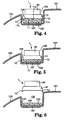
- the width "W" of the main body 10, 20, or 30 is almost equal to that of the roof groove 105, so that the main body 10, 20, 30 is smoothly fitted in the roof groove 105 as indicated in Figs. 4, 7 and 9. Accordingly, the appearance not only at the central part of a sealant 120, but edge parts 121 of the sealant 120 is maintained good as is clear from, e.g. , Fig. 6.
- the width "W" of the main body 10, 20, or 30 is so selected as to cover the outer surface of the sealant.
- a metallic material such as stainless, aluminum, magnesium alloy, copper, iron or the like, or a resin material such as polyamide, polyimide, acryl, vinyl chloride, polyethylene, polystyrene, polyester, polyurethane, Teflon (Teflon is the trademark of polytetrafluoroethylene), etc.
- the sealant 120 used in the embodiments is, similar to the conventionally employed sealant, of a type, e.g., that is hardened after being heated by a general heating means such as a sealing oven or the like. Therefore, the material for the main body 10, 20, or 30 is suitably a heat-proof resin or metallic material to the heating temperature in the sealing oven.
- a metallic material is used as a material for the main body 10, 20, or 30, stainless that does not rust even in the long-time use is most fit.
- a fluoric resin such as Teflon (Teflon is the trademark for polytetrafluoroethylene) or the like showing release characteristics to the above sealant and favorable heat resistances is preferable.
- a molding surface 11 of the main body 10 in touch with an outer surface 122 of the sealant 120 molds the outer surface 122 of the sealant 120 which is a paste or heated to be softened in the above sealing oven.
- the molding surface 11 is constituted of a flat surface 11a and inclined surfaces 11c.
- the inclined surface 11c is an outer surface of a projecting part 13 projecting from the flat surface 11a at a side edge of the main body 10 in the widthwise direction.
- the molding surface 11 eliminates the rough of the outer surface 122 of the sealant 120 which is a cause for the above-described defective appearance, thereby to refine the sealed outer surface 122 of the sealant 120.
- the flat surface 11la makes the outer surface 122 of the molded sealant 120 smooth without projections/recesses thereby to shape the outer surface 122. Because of the presence of the inclined surfaces 11c, edge parts 121 in the widthwise direction of the sealant 120 are molded with ease into good appearance.
- the surface may be a smooth curve, e.g., arc as represented by a molding surface 21 in the main body 20 of Fig. 2.
- the whole surface may be a plane without the inclined surface 11a such as a molding surface 31 of the main body 30 indicated in Fig. 3.
- the sealant 120 before hardened is a rod with the width approximately equal to that of the flat surface 11a, the sealant 120 can be easily positioned to the main body 10 by the inclined surfaces 11c and readily supported to the main body 10.
- Characters, numbers, symbols or patterns may be cut in the molding surface 11, 21, 31. A portion where the characters, numbers, symbols or patterns are cut becomes a recessed part or a projecting part. The surface with the characters or the like eliminates the rough of the outer surface 122 of the sealant 120 which would result in the inferior appearance. Moreover, when the characters, numbers, symbols or patterns are engraved in the outer surface 122, the sealant 120 is formed in good shape.
- the molding surface 11, 21, 31 is desired to have release characteristics to the sealant 120.
- the molding tool 1, etc. can be smoothly detached from the sealant 120 after molding the sealant 120 without hurting the outer surface 122 of the molded sealant 120.
- a release agent including at least in one of silicone resin, silicone rubber, fluoric resin or fluoric rubber is fit, because the above agent is effective irrespective of the kind of resin included in the sealant 120.
- the agent is applied to the molding surface 11, 21, 31 by a general application means such as a roller, spray or brush, etc.
- a concrete example of the agent is "MOLD RELEASE AGENT RESIN RELEASE” by Minnesota Mining & Manufacturing Company (3M) which is available in a spray can.
- the release member alike desirably contains at least in one of silicone resin, silicone rubber, fluoric resin or fluoric rubber from the same reason as for the above agent.
- the release member can be attached to the molding surface 11, 21, 31 via a tackifier or an adhesive.
- "TEFLON FILM ADHESIVE TAPE #5480" produced by Minnesota Mining & Manufacturing Company (3M) is an example of the release member. Teflon is the trademark for polytetrafluoroethylene.
- the pressing member 50, 60 will be discussed below.
- the pressing member 50, 60 is, as indicated in Figs. 1-3, set on a surface 12, 22, 32 facing the corresponding molding surface 11, 21, 31 of the main body 10, 20, 30.
- the pressing member 50 is a slim plate-like plastic magnet as shown in Figs. 1 and 2.
- the pressing member 50 has a slightly smaller width than the width "W" of the main body 10, 20 and extends nearly the whole length of the main body 10, 20.
- the pressing member 50 may be constituted of a plurality of plastic magnets arranged discontinuously in the longitudinal direction of the main body 10, 20 with a predetermined distance to each other on the surface 12, 22 of the main body.
- the pressing member 50 presses the main body 10, 20 to the jointed part 107 by magnetic force acting between the jointed part 107 and the pressing member 50.
- the plastic magnet of the pressing member 50 preferably includes a heat-proof resin.
- the plastic magnet easily reduces the weight of the whole of the molding tool of the present embodiments and, at the same time little changes the shape and size even when it is repeatedly heated and cooled for a long time. That is, the whole molding tool for sealant is prevented from changing the shape and size.
- the heat-proof resin is favorably a thermosetting resin including an epoxy resin, or a heat-proof thermoplastic resin such as polyamide, polyether ketone, polyphenylene-sulfide, etc.
- the pressing member 50 is attached to the surface 12, 22 of the main body 10, 20, for example, by an adhesive or the like.
- the jointed part 107 is formed at the bottom of the roof groove 105 and the molding tool is used while being fitted in the roof groove 105, although it is possible to use the molding tool equipped with the pressing member 50 as in Figs. 4 and 7, the molding tool with another pressing member 60 as in Fig. 3 may be employable.
- the pressing member 60 is a hollow tubular member, for instance, which is formed of an expansible material. Both ends of the member are shut, for example, by metallic lid plates 61.
- the tubular pressing member 60 is better to be elliptic having a longer diameter in the widthwise direction of the main body 30.
- an injection port (not shown) is formed at least in one of the lid plates 61 to inject gas or the like fluid to a hollow 63 of the pressing member 60 having both ends closed by the lid plates 61. Gas or the like is supplied to or discharged from the hollow part 63 through the injection port.
- the width of the pressing member 60 in a direction of the above longer diameter is, as is clearly recognized in Fig.
- the pressing member 60 as above is set to the surface 31 of the main body 30, for example, by an adhesive or the like.
- each part of the larger diameter of the elliptic pressing member 60 is positioned at least inside the roof groove 105. Unless the part of the larger diameter is present inside the roof groove 105, it is necessary to press the pressing member 60 further into the roof groove 105.
- the pressing member 60 expands when gas or the like is injected into the hollow part 63 of the member 60, bringing each area 62 of the outer surface corresponding to the above part of the larger diameter of the pressing member 60 into touch with side walls 101a, 103a of the roof groove 105.
- the area 62 presses the side walls 101a, 103a.
- the molding tool 3 fitted in the roof groove 105 is controlled by the friction force between the area 62 and the side walls 101a, 103a not to move in a direction to slip out from the roof groove 105. Therefore, as gas is injected more to the pressing member 60 which further expands the pressing member, the main body 30 with the pressing member 60 is depressed towards the bottom of the roof groove 105, accordingly pressing the sealant 120.
- Heat-proof rubber is included as a favorable material of the pressing member 60.
- the heat-proof rubber is ethylene-propylene-diene-methylene (EPDM), chlorosulfonated polyethylene (named as "Hypalon” by Du Pont), silicone rubber basically composed of polysiloxane or fluoric rubber such as hexafluoropropylenevinylidene fluoride copolymer, etc.
- the area 62 of the pressing member 60 has such friction resistance that allows the main body 30 to press the sealant 120.
- the friction resistance is easily obtained if the pressing member 60 contains the aforementioned rubber material, it is more desired that the outer surface of the pressing member 60 is coated with cross-linked polyurethane or the like resin to generate viscosity at the heating temperature of the sealant for the purpose of enhancing the friction resistance.
- the heating treatment for the sealant 120 to be used for sealing the jointed part of the exterior panel with the molding tool 1, 2, 3 is carried out in the sealing oven described before.
- the sealant 120 is preferably of a kind partially or totally hardened. If the sealant is a type not hardened, the sealant may be melted or softened in some cases and deformed in a drying process after the exterior panel is face coated, or the material wrinkles as a result of the shrinkage when the face coating film is hardened. The appearance of the molded sealant may be thus hurt.
- the setting sealant 120 is, for example, "MELT SEAL TAPE #E9280" manufactured by Minnesota Mining & Manufacturing Company.
- the above sealant 120 is preferred to include a volume expansion agent.
- the volume expansion agent offsets the volumetric shrinkage brought about when the sealant 120 is solidified or hardened, thereby preventing a gap from being generated between the molding surface 11, etc. of the molding tool 1, etc. and the outer surface 122 of the sealant 120. Accordingly, the molding surface 11, 21, 31 is tightly held in touch with the outer surface 122.
- the outer surface 122 of the sealant 120 is rendered totally uniform.
- OBSH 4,4'-oxybisbenzenesulfonyl-hydrazide
- azodicarbonamide or the like component generating gas when decomposed with heat, or thermal expansive microcapsules involving hydrocarbon is suitable.
- microcapsules are specifically, e.g., "MATSUMOTO MICROSPHERE F-80” manufactured by (Matsumoto Oil & Fat Co., Ltd.), “(EXPANCEL) DU551” by (Kemanovel, Inc.), etc.
- the above sealant 120 is arranged at the upper surface of the jointed part 107 located at the bottom in the roof groove 105 in a molding process.
- the molding tool 1 is fitted in the roof groove 105 so that the molding surface 11 thereof is in touch with the outer surface 122 of the sealant 120. While the molding surface 11is kept in touch with the outer surface 122 of the sealant 120, the molding tool 1 is disposed to allow the sealant 120 to be pressed to the jointed part 107 by means of the molding surface ".
- the molding surface 11, 21 of the main body 10, 20 presses the sealant 120 to the jointed part 107 owing to magnetic force acting between the plastic magnet as the pressing member 50 and the jointed part 107 of the exterior panel made of a metallic material.
- the molding tool 3 is used, as shown in Fig. 9, when gas or the like is injected to the hollow part 63 of the pressing member 60 after the molding tool 3 is fitted in the roof groove 105, the pressing member 60 is expanded, whereby the molding surface 31 of the main body 30 presses the sealant 120 against the jointed part 107 as described above.
- the sealant 120 While the molding surface 11, 21, or 31 presses the sealant 120 to the jointed part 107, the sealant 120 is heated by the sealing oven. Therefore, the outer surface 122 of the sealant 120 of a paste or heated and then softened in the sealing oven is molded by the molding surface 11, 21, 31 as illustrated in Figs. 5, 7 and 10, and moreover the sealant 120 is molded in conformity with the shape of the jointed part 107 to tightly shield the jointed part 107. The sealant is subsequently hardened with heat.
- the outer surface 122 of the sealant 120 is molded in conformity with the shape of the molding surface 11, 21, 31 without the projections/recesses of the jointed part 107 transferred thereto.
- the molding tool 1, 2, 3 is removed from the roof groove 105, thus completing the formation of the outer surface 122 of the sealant 120.
- the molding tool 3 is removed from the roof groove 105 after gas or the like is discharged from the hollow part 63 of the pressing member 60.
- the molding surface of the molding tool is pressed to the outer surface of the sealant of a paste or solid rod, the outer surface of the sealant is formed corresponding to the shape of the molding surface, and accordingly, projections/recesses formed in the jointed part are prevented from being transferred to the outer surface of the sealant. It becomes consequently unnecessary to install a decorative member such as a roof molding or the like referred to earlier, reducing the number of parts and steps in assembling, for example, the roof panel. After sealing the jointed part, furthermore, the whole roof including the sealant can be coated easily in the same color.
- the molding tool is applied to the roof groove 105 in the foregoing embodiments
- the molding tools 1, 2 using a magnet as the pressing member are not restricted to the application to the roof groove 105, but may be employable to a sealant set at a rough jointed part which is positioned at a part of a plane.
- the main body 10, 20, 30 is provided with the pressing member 50, 60 in the above embodiments, the pressing member 50, 60 may be omitted and instead, the sealant is arranged to be pressed by the 15 weight of the main body 10, 20, or 30 itself.
- this arrangement is limited only to a case where the jointed part 107 is located in a direction of gravity to the main body 10, 20, 30.
- the pressing member 50, 60 is arranged for the main body 10, 20, 30, a separate pressing means is not necessary, thereby lightening the total weight of the molding tool 1, etc.
- the pressing member 50, 60 is set to the main body 10, 20, 30 in the above description, the present invention is not restricted to above and the pressing member 50, 60 may be formed integrally with the main body 10, 20, 30 .
- the jointed part 107 is formed of such material attracted by magnetism as iron or the like, or is magnetized in the above examples. However, if the jointed part 107 is not formed of a magnetic material, a magnetizing member, e.g., a permanent magnet or an electromagnet may be provided at the rear surface of the jointed part opposite to the front surface where the sealant is arranged.
- a magnetizing member e.g., a permanent magnet or an electromagnet
- the main body can be formed of a magnetized material such as a magnet or the like. Supposing that the main body is formed of the magnetized material, when the jointed part is magnetizable or magnetizable member is provided at the rear surface of the jointed part, a molding tool having no pressing member can be provided.
- the magnetized material forming the main body is favorably the plastic magnet as described before.
- the sealant 120 is molded thereby to tightly seal the jointed part 107 by bringing, for example, the molding surface 11 of the molding tool 1 for sealant in touch with the outer surface 122 of the sealant 120 after the sealant 120 is disposed at the jointed part 107.
- the method is not limited to the above, and a sealant with a molding tool may be prepared at the molding surface 11 or the like by making the outer surface of the sealant touch with the molding surface 11 or the like beforehand, which is to be disposed at the jointed part 107.
- the above sealant with the molding tool is manufactured by a supplier of the sealant and fed to a user of the sealant.
- the user can use the sealant with the molding tool in the same manner as the conventional sealant. Therefore, the sealing method allows the user to omit the disposing process in which the molding surface is brought in touch with the outer surface of the sealant after the sealant is disposed at the jointed part 107, with enabling molding of the outer surface of the sealant after the jointed part 107 is sealed.
- the sealant with the molding tool provides recycling of the molding tool 1 or the like for sealant, etc. That is, the molding tool 1 or the like for sealant used by the user is withdrawn to the supplier, so that a fresh sealant with a molding tool is produced and supplied from the withdrawn molding tool 1 or the like for sealant.
- the sealant with the molding tool is formed by utilizing the tackiness of the sealant itself.
- sealants there are two kinds of sealants, i.e., (i) one that is tack-free almost without any tackiness at normal temperatures and (ii) one that loses its tack strength after heated and melted, thereby sealing the jointed part although it shows the tack at normal temperatures.
- a sealant of the above type (ii) for the sealant with the molding tool.
- the sealant with the molding tool may be formed by laminating a sealant of the type (ii) with a sealant of the type (i).
- the outer surface of the sealant while kept in touch with the molding surface 11 of the molding tool for sealant is partially or totally fused to the molding surface 11 or the like, whereby the sealant is temporarily bonded with the molding surface 11 or the like. In consequence, the sealant with the molding tool is obtained.
- the outer surface of the sealant is partially or totally fused to the molding surface 11 or the like by heating from the side of the molding tool for sealant or by way of fusing such as ultrasonic fusing, etc.
- the sealant with the molding tool for sealant via a tackifier.
- the tackifier is desirably of a type that has the tackiness at normal temperatures, but loses the tackiness through setting when it is heated and melted, thereby sealing the jointed part 107.
- the molding surface of the molding tool covers the outer surface of the sealant to be in touch with the outer surface of the sealant, thereby pressing the outer surface to the jointed part. Therefore, the outer surface of the sealant is formed in conformity with the shape of the molding surface. In consequence, it is prevented that the projections/recesses of the jointed part are transferred to the outer surface of the sealant. Since it is not necessary to install the decorative member such as the roof molding or the like, the number of parts and working steps when the roof panel or the like is assembled is decreased.
- the molding tool for sealant of the present invention in the case where the molding tool is arranged at a groove of a generally U-shaped cross section, a tubular body is expanded to press the outer surface of the sealant by the molding surface of the main body. Therefore, the molding surface allows the outer surface of the sealant to be formed in conformity with the shape thereof. The projections/recesses of the jointed part are hence prevented from being transferred to the outer surface of the sealant. Since it is not necessitated to attach the decorative member such as the roof molding or the like, the number of parts and working steps to assemble, for instance, a roof panel is reduced.
- the disposing process to bring the molding surface of the molding tool for sealant in touch with the outer surface of the sealant after the sealant is disposed at the jointed part becomes omissible, and at the same time, the outer surface of the sealant can be molded after the sealant seals the jointed part.
Landscapes
- Engineering & Computer Science (AREA)
- Mechanical Engineering (AREA)
- Chemical & Material Sciences (AREA)
- Composite Materials (AREA)
- Lining Or Joining Of Plastics Or The Like (AREA)
- Vehicle Interior And Exterior Ornaments, Soundproofing, And Insulation (AREA)
- Vehicle Waterproofing, Decoration, And Sanitation Devices (AREA)
- Seal Device For Vehicle (AREA)
Claims (10)
- Formwerkzeug (1,2,3) zum Formen einer Außenfläche (122) einer aus Harz bestehenden Dichtmasse (120) zum Abdecken eines vorstehenden oder eingelassenen Teils eines zusammengesetzten Teils (107), bei dem zwei Elemente derart miteinander verbunden sind, dass sie eine Abdichtung an der Naht des zusammengesetzten Teils (107) bilden, und bei dem das zusammengesetzte Teil (107) am Boden (106) einer Nut (105) angeordnet ist und sich die Dichtmasse in der Nut (105) befindet, wobei das Formwerkzeug (1,2,3)
einen Hauptkörper (10,20,30) mit einer Formfläche (11,21,31) aufweist, welche entlang des zusammengesetzten Teils (107) verläuft und mindestens die Außenfläche (122) der Dichtmasse (120) berührt,
dadurch gekennzeichnet, dass
der Hauptkörper in der Nut (105) anzuordnen ist und dadurch die Außenfläche (122) derselben zusammendrückt und formt. - Formwerkzeug (1,2,3) für eine Dichtmasse (120) nach Anspruch 1, bei dem der Hauptkörper (10,20,30) plattenförmig ausgeführt ist und eine Länge aufweist, die die gesamte Außenfläche (122) der Dichtmasse (120) in der Nut (105) abdeckt, und eine Breite aufweist, die ungefähr der der Nut (105) gleich ist, so dass der Hauptkörper (10,20,30) leicht in die Nut (105) eingepasst werden kann.
- Formwerkzeug (1,2,3) für eine Dichtmasse (120) nach Anspruch 2, bei dem die Breite des plattenförmigen Hauptkörpers (10,20,30) die Außenfläche (122) der Dichtmasse (120) abdeckt.
- Formwerkzeug (1,2,3) für eine Dichtmasse (120) nach einem der vorhergehenden Ansprüche, bei dem der Hauptkörper (10,20,30) gegenüberliegende Seitenkanten und ein vorstehendes Teil (13,23) an jeder Seitenkante aufweist, die verhindern, dass die Dichtmasse (120) in einer der Zusammendrückrichtung entlang der Seitenwände der Nut (105) entgegengesetzten Richtung ausläuft, wenn die Dichtmasse (120) von der Formfläche (11,21,31) zusammengedrückt wird.
- Formwerkzeug (1,2,3) für eine Dichtmasse (120) nach einem der vorhergehenden Ansprüche, dadurch gekennzeichnet, dass das zusammengesetzte Teil (107) magnetisiert ist oder ein magnetisierbares Element auf der Rückseite des zusammengesetzten Teils (107) angeordnet ist, und dass das Formwerkzeug (1,2,3) ein magnetisches Element aufweist, das von dem zusammengesetzten Teil (107) oder dem magnetisierbaren Element angezogen wird, so dass das Zusammendrücken durch die Magnetkraft des magnetischen Elements erfolgt.
- Formwerkzeug (1,2,3) für eine Dichtmasse (120) nach einem der Ansprüche 1 bis 4, dadurch gekennzeichnet, dass ein Magnetelement an der Rückseite des zusammengesetzten Teils (107) angeordnet ist und das Formwerkzeug (1,2,3) eine von dem Magnetelement angezogene Substanz aufweist, so dass das Zusammendrücken durch die Magnetkraft des Magnetelements erfolgt.
- Formwerkzeug (1,2,3) für eine Dichtmasse (120) nach einem der vorhergehenden Ansprüche, das ein auf einer Fläche (12,22,32) des Hauptkörpers (10,20,30) gegenüber der Formfläche (11,21,31) angebrachtes Zusammendrückelement (50,60) aufweist, welches den Hauptkörper (10,20,30) in Richtung des zusammengesetzten Teils (107) zusammendrückt und dadurch die Formfläche (11,21,31) auf die Außenfläche (122) der Dichtmasse (120) drückt.
- Formwerkzeug (1,2,3) für eine Dichtmasse (120) nach Anspruch 7, dadurch gekennzeichnet, dass das Zusammendrückelement (50,60) magnetisiert wird, wenn das zusammengesetzte Teil (107) magnetisierbar ist oder ein magnetisierbares Element auf der Rückseite des zusammengesetzten Teils (107) angeordnet ist, so dass das Zusammendrücken durch die zwischen dem zusammengesetzten Teil (107) und dem Zusammendrückteil (50,60) wirkende Magnetkraft erfolgt.
- Formwerkzeug (1,2,3) für eine Dichtmasse (120) nach einem der vorhergehenden Ansprüche, dadurch gekennzeichnet, dass die beiden zusammengesetzten Teile eine Nut (105) mit einem im wesentlichen U-förmigen Querschnitt bilden und das Formwerkzeug (1,2,3) aufweist:einen in die Nut (105) einpassbaren plattenförmigen Hauptkörper (10,20,30) mit einer entlang der Nut (105) verlaufenden Formfläche (11,21,31) und einer Breite, die ungefähr der Breite gleich ist, die quer zur Längserstreckung gerichtet ist, der derart positioniert ist, dass er einen Kontakt mit der Außenfläche (122) der Dichtmasse (120) ermöglicht, wodurch die Außenfläche (122) der Dichtmasse (120) zusammengedrückt und geformt wird, undein Zusammendrückelement (50,60) mit einem dehnbaren rohrförmigen Körper auf einer Fläche des Hauptkörpers (10,20, 30) gegenüber der Formfläche (11,21,31), der sich ausdehnt, wenn eine den rohrförmigen Körper erweiternde Flüssigkeit in einen Hohlraum des Körpers eingespritzt wird, wodurch die in Tiefenrichtung der Nut (105) verlaufende rechte und linke Seitenwand der Nut (105) zusammengedrückt werden, so dass die Formfläche (11,21,31) auf die Außenfläche (122) der Dichtmasse (120) drücken kann.
- Dichtverfahren mit einem Formwerkzeug (1,2,3) zum Formen einer Außenfläche (122) einer aus Harz bestehenden Dichtmasse (120) zum Abdecken eines vorstehenden oder eingelassenen Teils eines zusammengesetzten Teils (107), bei dem zwei Elemente des zusammengesetzten Teils (107) zum Abdichten der Naht des zusammengesetzten Teils miteinander verbunden werden und das zusammengesetzte Teil (107) am Boden (106) einer Nut (105) angeordnet ist und sich die Dichtmasse (120) in der Nut (105) befindet,
dadurch gekennzeichnet, dass das Verfahren folgende Schritte um fasst:Bereitstellen eines Formwerkzeugs (1,2,3) mit einem Hauptkörper (10,20,30), der in einer Nut (105) angeordnet werden kann, und Bereitstellen einer Formfläche (11,21,31) zum Formen der Außenfläche (122) der Dichtmasse (120),Anordnen des Hauptkörpers (10,20,30) des Formwerkzeugs (1,2, 3) in der Nut (105), so dass die Formfläche (11,21,31) mit der Außenfläche (122) der Dichtmasse (120) in Berührung gebracht wird, wodurch die Außenfläche (122) der Dichtmasse (120) zusammengedrückt und geformt wird,Erwärmen der Dichtmasse (120), während die Formfläche (11, 21,31) mit der Außenfläche (122) der Dichtmasse (120) in Berührung ist, undEntfernen des Formwerkzeugs (1,2,3) von der Dichtmasse (120).
Applications Claiming Priority (5)
| Application Number | Priority Date | Filing Date | Title |
|---|---|---|---|
| JP6296331A JPH08159288A (ja) | 1994-11-30 | 1994-11-30 | シール材用成形部材及び該シール材用成形部材を使用するシール方法 |
| JP29633194 | 1994-11-30 | ||
| JP296331/94 | 1994-11-30 | ||
| US08/552,911 US6056526A (en) | 1994-11-30 | 1995-11-03 | Molding tool for sealant material |
| PCT/US1995/014797 WO1996016793A1 (en) | 1994-11-30 | 1995-11-03 | Molding tool for sealant and sealing method using the molding tool |
Publications (2)
| Publication Number | Publication Date |
|---|---|
| EP0797501A1 EP0797501A1 (de) | 1997-10-01 |
| EP0797501B1 true EP0797501B1 (de) | 2000-08-02 |
Family
ID=26560637
Family Applications (1)
| Application Number | Title | Priority Date | Filing Date |
|---|---|---|---|
| EP95942419A Expired - Lifetime EP0797501B1 (de) | 1994-11-30 | 1995-11-03 | Formwerkzeug für ververbindungsmittel und verbindeverfahren unter verwendung des formwerkzeuges |
Country Status (4)
| Country | Link |
|---|---|
| EP (1) | EP0797501B1 (de) |
| JP (1) | JPH08159288A (de) |
| CA (1) | CA2205395A1 (de) |
| WO (1) | WO1996016793A1 (de) |
Cited By (1)
| Publication number | Priority date | Publication date | Assignee | Title |
|---|---|---|---|---|
| US11511610B2 (en) | 2018-11-12 | 2022-11-29 | Shape Corp. | Vehicle door carrier with integrated edge seal and method of manufacture |
Families Citing this family (10)
| Publication number | Priority date | Publication date | Assignee | Title |
|---|---|---|---|---|
| US5939007A (en) * | 1994-08-31 | 1999-08-17 | Sikorsky Aircraft Corporation | Method for manufacture of a fiber reinforced composite spar for rotary wing aircraft |
| US5964979A (en) * | 1997-08-15 | 1999-10-12 | 3M Innovative Properties Company | Sealing method and article |
| FR2792591B1 (fr) * | 1999-04-21 | 2001-07-27 | Peugeot Citroen Automobiles Sa | Enjoliveur universel, notamment pour vehicule automobile |
| JP2003063251A (ja) * | 2001-08-22 | 2003-03-05 | Torantekkusu:Kk | 車両における防水用キャンバスの取付構造 |
| DE10145230A1 (de) * | 2001-09-13 | 2003-04-24 | Karmann Gmbh W | Karosserie und Verfahren sowie Vorrichtung zum Füllen einer Fuge bei einer Karosserie |
| JP4787596B2 (ja) * | 2005-10-28 | 2011-10-05 | 株式会社ブリヂストン | ガスケットの製造方法、及びシール構造 |
| WO2011001510A1 (ja) * | 2009-06-30 | 2011-01-06 | トヨタ自動車株式会社 | ルーフサイド部成形方法及び掻取工具 |
| WO2016063559A1 (ja) * | 2014-10-23 | 2016-04-28 | 本田技研工業株式会社 | シール剤塗布方法、これに用いるシール剤整形装置及びこれにより整形されたシール剤 |
| CN107921675B (zh) * | 2015-08-26 | 2020-08-25 | 本田技研工业株式会社 | 树脂成型方法和成型模具 |
| JP7043817B2 (ja) * | 2017-12-07 | 2022-03-30 | トヨタ自動車株式会社 | 車両部材の接合構造 |
Family Cites Families (6)
| Publication number | Priority date | Publication date | Assignee | Title |
|---|---|---|---|---|
| US2677633A (en) * | 1950-08-07 | 1954-05-04 | Rohr Aircraft Corp | Processes for sealing the seams and joints of structures fabricated of nonporous materials |
| JPS60237267A (ja) * | 1984-05-09 | 1985-11-26 | Suriibondo:Kk | 複合成形物の成形方法 |
| US4626391A (en) * | 1984-12-24 | 1986-12-02 | General Motors Corporation | Method of finishing a body panel joint |
| EP0416653B2 (de) * | 1989-09-08 | 2002-07-31 | Norton Company | Verfahren und Vorrichtung zur Herstellung einer Dichtung auf einer Fläche eines Gegenstands |
| MX9301049A (es) * | 1992-02-28 | 1995-01-31 | Dow Corning Toray Silicone | Metodo de sellado para un cuerpo estructural en forma de recipiente. |
| JPH1152049A (ja) * | 1997-07-31 | 1999-02-26 | Nkk Corp | 炉内の湯面レベル計測装置 |
-
1994
- 1994-11-30 JP JP6296331A patent/JPH08159288A/ja active Pending
-
1995
- 1995-11-03 CA CA002205395A patent/CA2205395A1/en not_active Abandoned
- 1995-11-03 WO PCT/US1995/014797 patent/WO1996016793A1/en not_active Ceased
- 1995-11-03 EP EP95942419A patent/EP0797501B1/de not_active Expired - Lifetime
Cited By (1)
| Publication number | Priority date | Publication date | Assignee | Title |
|---|---|---|---|---|
| US11511610B2 (en) | 2018-11-12 | 2022-11-29 | Shape Corp. | Vehicle door carrier with integrated edge seal and method of manufacture |
Also Published As
| Publication number | Publication date |
|---|---|
| CA2205395A1 (en) | 1996-06-06 |
| WO1996016793A1 (en) | 1996-06-06 |
| EP0797501A1 (de) | 1997-10-01 |
| JPH08159288A (ja) | 1996-06-21 |
Similar Documents
| Publication | Publication Date | Title |
|---|---|---|
| US6056526A (en) | Molding tool for sealant material | |
| EP0797501B1 (de) | Formwerkzeug für ververbindungsmittel und verbindeverfahren unter verwendung des formwerkzeuges | |
| US5730446A (en) | Sealing strip suitable for sealing a hem flange | |
| US6375878B1 (en) | Foam shut-off method | |
| JP4567335B2 (ja) | オリフィス密封物的障壁 | |
| EP0920849A3 (de) | Beutel für Infusionslösungen und Verfahren zur Herstellung | |
| US20030168814A1 (en) | Door and/or window frame | |
| AU5432998A (en) | Sealing method and article | |
| JPH04119828A (ja) | 取付具を有する発泡基材製品の製造方法 | |
| EP1681245A4 (de) | Polyesterbehälter, verfahren zur herstellung desselben und verfahren zur abdichtung des polyesterbehälters | |
| EP0916878A3 (de) | Methode zur Abdichtung zweier Teile und Dichtung dazu | |
| EP0186319B1 (de) | Fertigbearbeitung einer angeformten Karosserieblechverbindung | |
| JP2005047263A (ja) | 窓組立体の製造方法及び窓板 | |
| MXPA97003888A (en) | Sealing molding tool and sealing method using the molt tool | |
| EP2796345A1 (de) | Abdeckhaubenstruktur für einen äusseren plattenverbindungsteil einer fahrzeugkarosserie | |
| US20160288735A1 (en) | Exterior assembly and method for coupling an exterior assembly to a vehicular frame | |
| JP4229247B2 (ja) | ルーフモール及びその塗装方法 | |
| US20080224342A1 (en) | Method For Forming Two-Tone Parts For Automotive Interior Applications | |
| JP2017077662A (ja) | インサート成形法 | |
| JP3175787B2 (ja) | モール付き板状体の製造方法 | |
| JPH11235763A (ja) | 自動車用熱可塑性押出し成形品及びその端末処理方法 | |
| DE10336864A1 (de) | Dichtung, insbesondere zum Abdichten der karosserie eines Kraftfahrzeugs | |
| JP2958244B2 (ja) | 表皮一体発泡成形方法 | |
| JPH0893068A (ja) | 目地構造 | |
| JPH0798339B2 (ja) | 自動車用昇降ウインドウの製造方法 |
Legal Events
| Date | Code | Title | Description |
|---|---|---|---|
| PUAI | Public reference made under article 153(3) epc to a published international application that has entered the european phase |
Free format text: ORIGINAL CODE: 0009012 |
|
| 17P | Request for examination filed |
Effective date: 19970623 |
|
| AK | Designated contracting states |
Kind code of ref document: A1 Designated state(s): DE ES FR GB IT |
|
| 17Q | First examination report despatched |
Effective date: 19981113 |
|
| GRAG | Despatch of communication of intention to grant |
Free format text: ORIGINAL CODE: EPIDOS AGRA |
|
| GRAG | Despatch of communication of intention to grant |
Free format text: ORIGINAL CODE: EPIDOS AGRA |
|
| GRAH | Despatch of communication of intention to grant a patent |
Free format text: ORIGINAL CODE: EPIDOS IGRA |
|
| GRAH | Despatch of communication of intention to grant a patent |
Free format text: ORIGINAL CODE: EPIDOS IGRA |
|
| GRAA | (expected) grant |
Free format text: ORIGINAL CODE: 0009210 |
|
| AK | Designated contracting states |
Kind code of ref document: B1 Designated state(s): DE ES FR GB IT |
|
| PG25 | Lapsed in a contracting state [announced via postgrant information from national office to epo] |
Ref country code: IT Free format text: LAPSE BECAUSE OF FAILURE TO SUBMIT A TRANSLATION OF THE DESCRIPTION OR TO PAY THE FEE WITHIN THE PRE;WARNING: LAPSES OF ITALIAN PATENTS WITH EFFECTIVE DATE BEFORE 2007 MAY HAVE OCCURRED AT ANY TIME BEFORE 2007. THE CORRECT EFFECTIVE DATE MAY BE DIFFERENT FROM THE ONE RECORDED.SCRIBED TIME-LIMIT Effective date: 20000802 Ref country code: FR Free format text: LAPSE BECAUSE OF FAILURE TO SUBMIT A TRANSLATION OF THE DESCRIPTION OR TO PAY THE FEE WITHIN THE PRESCRIBED TIME-LIMIT Effective date: 20000802 Ref country code: ES Free format text: THE PATENT HAS BEEN ANNULLED BY A DECISION OF A NATIONAL AUTHORITY Effective date: 20000802 |
|
| REF | Corresponds to: |
Ref document number: 69518254 Country of ref document: DE Date of ref document: 20000907 |
|
| PGFP | Annual fee paid to national office [announced via postgrant information from national office to epo] |
Ref country code: DE Payment date: 20001019 Year of fee payment: 6 |
|
| PGFP | Annual fee paid to national office [announced via postgrant information from national office to epo] |
Ref country code: GB Payment date: 20001020 Year of fee payment: 6 |
|
| EN | Fr: translation not filed | ||
| PLBE | No opposition filed within time limit |
Free format text: ORIGINAL CODE: 0009261 |
|
| STAA | Information on the status of an ep patent application or granted ep patent |
Free format text: STATUS: NO OPPOSITION FILED WITHIN TIME LIMIT |
|
| 26N | No opposition filed | ||
| PG25 | Lapsed in a contracting state [announced via postgrant information from national office to epo] |
Ref country code: GB Free format text: LAPSE BECAUSE OF NON-PAYMENT OF DUE FEES Effective date: 20011103 |
|
| REG | Reference to a national code |
Ref country code: GB Ref legal event code: IF02 |
|
| GBPC | Gb: european patent ceased through non-payment of renewal fee |
Effective date: 20011103 |
|
| PG25 | Lapsed in a contracting state [announced via postgrant information from national office to epo] |
Ref country code: DE Free format text: LAPSE BECAUSE OF NON-PAYMENT OF DUE FEES Effective date: 20020702 |