EP0795664A2 - Einsteckschloss - Google Patents
Einsteckschloss Download PDFInfo
- Publication number
- EP0795664A2 EP0795664A2 EP97101279A EP97101279A EP0795664A2 EP 0795664 A2 EP0795664 A2 EP 0795664A2 EP 97101279 A EP97101279 A EP 97101279A EP 97101279 A EP97101279 A EP 97101279A EP 0795664 A2 EP0795664 A2 EP 0795664A2
- Authority
- EP
- European Patent Office
- Prior art keywords
- bolt
- lock
- closed
- slide
- locking
- Prior art date
- Legal status (The legal status is an assumption and is not a legal conclusion. Google has not performed a legal analysis and makes no representation as to the accuracy of the status listed.)
- Granted
Links
Images


Classifications
-
- E—FIXED CONSTRUCTIONS
- E05—LOCKS; KEYS; WINDOW OR DOOR FITTINGS; SAFES
- E05B—LOCKS; ACCESSORIES THEREFOR; HANDCUFFS
- E05B65/00—Locks or fastenings for special use
- E05B65/10—Locks or fastenings for special use for panic or emergency doors
- E05B65/1086—Locks with panic function, e.g. allowing opening from the inside without a ley even when locked from the outside
-
- E—FIXED CONSTRUCTIONS
- E05—LOCKS; KEYS; WINDOW OR DOOR FITTINGS; SAFES
- E05B—LOCKS; ACCESSORIES THEREFOR; HANDCUFFS
- E05B59/00—Locks with latches separate from the lock-bolts or with a plurality of latches or lock-bolts
-
- E—FIXED CONSTRUCTIONS
- E05—LOCKS; KEYS; WINDOW OR DOOR FITTINGS; SAFES
- E05B—LOCKS; ACCESSORIES THEREFOR; HANDCUFFS
- E05B63/00—Locks or fastenings with special structural characteristics
- E05B63/18—Locks or fastenings with special structural characteristics with arrangements independent of the locking mechanism for retaining the bolt or latch in the retracted position
- E05B63/20—Locks or fastenings with special structural characteristics with arrangements independent of the locking mechanism for retaining the bolt or latch in the retracted position released automatically when the wing is closed
- E05B2063/207—Automatic deadlocking
-
- E—FIXED CONSTRUCTIONS
- E05—LOCKS; KEYS; WINDOW OR DOOR FITTINGS; SAFES
- E05B—LOCKS; ACCESSORIES THEREFOR; HANDCUFFS
- E05B65/00—Locks or fastenings for special use
- E05B65/02—Locks or fastenings for special use for thin, hollow, or thin-metal wings
Definitions
- the invention relates to a mortise lock with a slide in the lock housing on at least two spaced guides parallel to the faceplate, which has an approximately diagonal to the faceplate slot for the engagement of a pin arranged on a bolt, the slide by means of a key bit or a Locking cylinder locking lug is pretensioned when the bolt is closed and is held in a tensioned position by means of a lock in such a way that it releases the locking device after the lock has been released by the key bit or the locking cylinder locking lug and the lock consists of a locking cam arranged on the slide and a latch arranged on a spring-loaded locking lever.
- DE 43 37 969 A1 has disclosed a self-locking security door lock.
- This security door lock is locked against shifting by a tumbler, which is built into the gear element.
- the latch can be unlocked or retracted by pressing the handle.
- a slide is used, which has a slot for the engagement of a pin arranged on a bolt. This slide is pretensioned by means of the locking lug of the locking cylinder.
- EP 0 575 701 A1 describes a mortise lock for an outer door.
- This lock of the aforementioned type should be designed so that different lock variants can be created in a simple manner.
- An exchange is also used for this, which consists of an exchangeable lower part and an exchangeable upper part. The interchangeable upper part is pivoted by the handle follower.
- the object of the invention is to integrate an interchangeable function and a panic function in a mortise lock of the aforementioned type, that is to say a mortise lock with a pretensionable slide mechanism with a slim design.
- a particularly advantageous embodiment of the guide of the interchangeable lower part is characterized; with the lower part aligned parallel to the faceplate, ie in the pre-closed position of the bolt, the central longitudinal axis of the elongated hole in the exchangeable lower part, in which the bolt of the bolt is guided, is inclined at an acute angle to the central longitudinal axis of the bolt. This causes the bolt to perform a rotational movement on the interchangeable lower part during its return movement, so that the interchangeable lower part comes into the access and thus into the movement path of the locking cylinder locking lug.
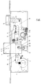
- the mortise lock is generally designated 1. It essentially consists of the lock plate 2, the face plate 3, the slide 4, the bolt 5 with pin 8, the locking lever 6 and the release lever 7.
- latch 23 and bolt 5 are locked. It can be seen that when the lock cylinder locking lug 11 is actuated in the image plane in a clockwise direction, the slide 4 guided in the guides 10 is displaced upward in the image plane, the locking cam 12 arranged on the slide 4 snaps into the catch 13 of the locking lever 6, the Spring 35 is tensioned.
- the locking lever 6 By driving over the release lever 7 with the locking cylinder locking lug 11 in a clockwise direction and then turning it briefly to the left, the locking lever 6 is pivoted to the left in the image plane by means of the release lever 7 and releases the latching cam 12, so that the slide 4 reaches the position shown in FIG. 1 and thus can trigger the bolt lock.
- the pin 8 arranged on the bolt 5 passes through the slot 9 in the slide 4.
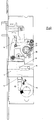
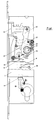
- FIG. 2 shows a situation in which the slide 4 and the release lever 7 are omitted, in which the slide 4 is in the position shown in FIG. 1, the lower change lever 14 being pressed against the stop 36 due to the force of the spring 15 .
- Figure 2 further shows that in this position of the lower change lever 14, the elongated hole 32 arranged in the change lever extends with its central longitudinal axis 33 inclined to the central longitudinal axis 34 of the bolt 5. The lower change lever 14 is thus in its lower position and cannot be actuated in this situation by means of the locking cylinder locking lug 11.
- the slide 4 has been moved upwards in the image plane, so that the latch 5 is enclosed.
- the pin 8 arranged on the latch 5 has moved to the right in the image plane; since the central longitudinal axis 33 of the elongated hole 32 is inclined to the central longitudinal axis 34 of the rain 5, the lower change lever 14 pivots to the right in the image plane and can thus be grasped by the lock cylinder locking lug 11 during a further closing tour and moved upwards in the image plane, as shown in 4 is shown.
- the stop 19 of the lower change lever 14 corresponds to a stop 20 of the upper change lever 22 (see FIGS. 5 and 6) in such a way that the latch 23 is enclosed.
- the change function is given.
- the panic function can also be seen from FIGS.
- a first panic lever 24 (see also FIG. 8) is connected to the nut 21, via which a two-armed second panic lever 27 is actuated, which is mounted in a pin 37 on the lock plate 2.
- the free end 28 of the longer leg 29 of the second panic lever 27 underpins the latching cam 12 of the slider 4 when the nut 21 is pivoted and lifts the slider 4 so that the latch 5 is retracted, i.e. gets into the inference position.
- the cam 30 arranged on the nut 21 runs against a corresponding driving lug 31 of the interchangeable upper part 22, so that the latch 23 is also closed. The panic function is thus given.
- FIGS. 5 to 8 show the components relevant for the change function and the panic function.
Landscapes
- Business, Economics & Management (AREA)
- Emergency Management (AREA)
- Engineering & Computer Science (AREA)
- Structural Engineering (AREA)
- Lock And Its Accessories (AREA)
- Conveying And Assembling Of Building Elements In Situ (AREA)
- Surgical Instruments (AREA)
- Fluid-Damping Devices (AREA)
- Mutual Connection Of Rods And Tubes (AREA)
Abstract
Description
- Die Erfindung betrifft ein Einsteckschloß mit einem im Schloßgehäuse an wenigstens zwei im Abstand zueinander angeordneten Führungen parallel zur Stulp geführten Schieber, welcher einen etwa diagonal zur Stulp verlaufenden Schlitz für den Eingriff eines an einem Riegel angeordneten Zapfens aufweist, wobei der Schieber mittels eines Schlüsselbartes oder einer Schließzylinderschließnase beim Riegelrückschluß vorgespannt und mittels einer Sperre derart in gespannter Stellung gehalten wird, daß er nach Lösen der Sperre durch den Schlüsselbart oder die Schließzylinderschließnase den Riegelvorschluß auslöst und die Sperre aus einem am Schieber angeordneten Rastnocken und einer an einem federbelasteten Sperrhebel angeordneten Falle besteht.
- In der DE 43 37 969 A1 ist ein selbstverriegelndes Sicherheitstürschloß offenbart worden. Dieses Sicherheitstürschloß ist gegen Verschieben durch eine Zuhaltung, die im Getriebeelement eingebaut ist, gesperrt. Dabei ist durch eine Drückerbetätigung der Riegel entsperrbar bzw. auch einfahrbar. Dazu wird ein Schieber verwendet, welcher einen Schlitz für den Eingriff eines an einem Riegel angeordneten Zapfens aufweist. Dieser Schieber wird mittels der Schließnase des Schließzylinders vorgespannt.
- In der EP 0 575 701 A1 wird ein Einsteckschloß für eine Außentür beschrieben. Dabei soll dieses Schloß der vorgenannten Art so ausgebildet werden, daß auf einfache Art und Weise verschiedene Schloßvarianten geschaffen werden können. Hierfür wird auch ein Wechsel verwendet, der aus einem Wechselunterteil und einem Wechseloberteil besteht. Dabei wird das Wechseloberteil durch die Drückernuß verschwenkt.
- Es ist wünschenswert, Einsteckschlösser der vorgenannten Gattung als sogenannte Rohrrahmenschlösser in möglichst schmaler Bauweise auszuführen. Dabei ist es insbesondere schwierig, zusätzliche Funktionen wie Wechselfunktion oder Panikfunktion in das Schloß zu integrieren.
- Aufgabe der Erfindung ist es, bei einem Einsteckschloß der vorgenannten Gattung, also einem Einsteckschloß mit einer vorspannbaren Schiebermechanik bei schmaler Bauweise eine Wechselfunktion und eine Panikfuktion zu integrieren.
- Die Erfindung löst die gestellte Aufgabe mit den Merkmalen des Anspruches 1; weitere Ausgestaltungen sind durch den Anspruch 2 gekennzeichnet.
- Nach der Lehre des Anspruches 1 ist ersichtlich, daß beim Betätigen des Schiebers im Sinne eines Riegelrückschlusses der untere Wechselhebel mittels des am Riegel angeordneten Zapfens automatisch in eine Position gebracht wird, mit der mittels derSchließzylinderschließnase die Wechselfunktion ausgelöst, d.h. die Falle rückgeschlossen werden kann. Ebenso ist ersichtlich, daß - bei vorgeschlossenem Riegel - in der Paniksituation durch Drückerbetätigung sowohl der Schieber in seine vorgespannte Stellung verbracht (und damit der Riegel rückgeschlossen) werden, als auch die Falle rückgeschlossen werden kann. Die Wechsel- und Panikfunktion ist somit in eine Schloßmechanik integriert, bei der der Schieber während des Riegelrückschlusses vorgespannt und der Riegelvorschluß durch kurze Schlüsselbetätigung schlagartig ausgelöst werden kann, wie dies Gegenstand der zeitlich gleichrangigen vorgenannten Anmeldung der Anmelderin ist.
- Im Anspruch 2 ist eine besonders vorteilhafte Ausführungsform der Führung des Wechselunterteils gekennzeichnet; bei parallel zur Stulp ausgerichtetem Wechselunterteil, d.h. in der vorgeschlossenen Stellung des Riegels, ist danach die Mittellängsachse des Langloches im Wechselunterteil, in dem sich der Zapfen des Riegels führt, in einem spitzen Winkel zur Mittellängsachse des Riegels geneigt. Dies bewirkt, daß der Riegel bei seiner Rückschlußbewegung eine Drehbewegung auf das Wechselunterteil ausübt, so daß das Wechselunterteil in den Zugriff und damit in die Bewegungsbahn der Schließzylinderschließnase gelangt.
- Die Erfindung wird nachfolgend anhand eines möglichen Ausführungsbeispieles näher erläutert. Es zeigen:
- Figur 1:
- das Einsteckschloß in einer Ansicht auf das Schließblech;
- Fig. 2 - 4:
- verschiedene Phasen der Schloßbetätigung unter Fortlassung des Schiebers und des Auslösehebels;
- Figur 5:
- den oberen Wechselhebel;
- Figur 6:
- den unteren Wechselhebel;
- Figur 7:
- die Falle;
- Figur 8:
- die beiden Panikhebel
- In der Figur 1 ist das Einsteckschloß allgemein mit 1 bezeichnet. Es besteht im wesentlichen aus dem Schloßblech 2, der Stulp 3, dem Schieber 4, dem Riegel 5 mit Zapfen 8, dem Sperrhebel 6 und dem Auslösehebel 7.
- In der Darstellung nach Figur 1 sind Falle 23 und Riegel 5 vorgeschlossen. Es ist ersichtlich, daß beim Betätigen der Schließzylinderschließnase 11 in der Bildebene in rechtsdrehendem Sinne der in der Führungen 10 geführte Schieber 4 in der Bildebene nach oben verschoben wird, der am Schieber 4 angeordnete Rastnocken 12 in die Rast 13 des Sperrhebels 6 einrastet, wobei die Feder 35 gespannt wird.
- Durch Überfahren des Auslösehebels 7 mit der Schließzylinderschließnase 11 in rechtsdrehendem Sinne und anschließender kurzer Linksdrehung wird mittels des Auslösehebels 7 der Sperrhebel 6 in der Bildebene nach links verschwenkt und gibt den Rastnocken 12 frei, so daß der Schieber 4 in die in Figur 1 dargestellte Position gelangen und damit den Riegelvorschluß auslösen kann. Der am Riegel 5 angeordnete Zapfen 8 durchläuft dabei den Schlitz 9 im Schieber 4.
- In der Figur 2 ist unter Fortlassung des Schiebers 4 und des Auslösehebels 7 eine Situation dargestellt, bei der sich der Schieber 4 in der in Figur 1 dargestellten Stellung befindet, wobei der untere Wechselhebel 14 aufgrund der Kraft der Feder 15 gegen den Anschlag 36 gedrückt wird. Figur 2 läßt weiter erkennen, daß in dieser Stellung des unteren Wechselhebels 14 das im Wechselhebel angeordnete Langloch 32 mit seiner Mittellängsachse 33 geneigt zur Mittellängsachse 34 des Riegels 5 verläuft. Der untere Wechselhebel 14 befindet sich somit in seiner unteren Position und kann in dieser Situation mittels der Schließzylinderschließnase 11 nicht betätigt werden.
- In der Darstellung nach Figur 3 ist der Schieber 4 in der Bildebene nach oben bewegt worden, so daß der Riegel 5 eingeschlossen ist. Dabei hat sich der am Riegel 5 angeordnete Zapfen 8 in der Bildebene nach rechts bewegt; da die Mittellängsachse 33 des Langloches 32 geneigt zur Mittellängsachse 34 des Reges 5 verläuft, verschwenkt der untere Wechselhebel 14 in der Bildebene nach rechts und kann so von der Schließzylinderschließnase 11 bei einer weiteren Schließtour hinterfaßt und in der Bildebene nach oben verschoben werden, wie dies in der Figur 4 dargestellt ist. Dabei korrespondiert der Anschlag 19 des unteren Wechselhebels 14 mit einem Anschlag 20 des oberen Wechselhebels 22 (siehe Figuren 5 und 6) derart, daß die Falle 23 eingeschlossen wird. Die Wechselfunktion ist damit gegeben. Aus den Figuren 3 und 4 ist zusätzlich die Panikfunktion erkennbar. Hierzu ist an der Nuß 21 ein erster Panikhebel 24 (siehe auch Figur 8) angeschlossen, über den ein zweiarmiger zweiter Panikhebel 27 betätigt wird, welcher in einem Zapfen 37 am Schloßblech 2 gelagert ist. Das freie Ende 28 des längeren Schenkels 29 des zweiten Panikhebels 27 unterfaßt beim Verschwenken der Nuß 21 den Rastnocken 12 des Schiebers 4 und hebt den Schieber 4 an, so daß der Riegel 5 eingefahren wird, d.h. in die Rückschlußposition gerät. Gleichzeitig läuft der an der Nuß 21 angeordnete Nocken 30 gegen eine entsprechende Mitnehmernase 31 des Wechseloberteils 22, so daß ebenfalls die Falle 23 rückgeschlossen wird. Die Panikfunktion ist somit gegeben.
- Es ist erkennbar, daß nach einer Rückziehung der Falle 23 mittels des zweiteiligen Wechsels bei der anschließenden Bewegung des Schlüsselbartes in linksdrehendem Sinne das Wechselunterteil in seinen Führungen 16 und 17 (die Führung 16 wird durch das Langloch 32 gebildet) in der Bildebene nach unten gleitet, so daß die Falle 23 in bekannter Weise durch entsprechende Federmittel wieder vorgeschlossen wird.
- In den Figuren 5 bis 8 sind die für die Wechselfunktion und die für die Panikfunktion relevanten Bauteile dargestellt.
-
- 1
- Einsteckschloß
- 2
- Schloßblech
- 3
- Stulp
- 4
- Schieber
- 5
- Riegel
- 6
- Sperrhebel
- 7
- Auslösehebel
- 8
- Zapfen am Riegel
- 9
- Schlitz im Schieber
- 10
- Führungen für Schieber
- 11
- Schließzylinderschließnase
- 12
- Rastnocken am Schieber
- 13
- Rast
- 14
- Wechselunterteil
- 15
- Feder
- 16
- Führung des Wechselunterteiles
- 17
- Führung des Wechselunterteiles
- 18
- Ende des Wechselunterteiles
- 19
- Anschlag am Wechselunterteil
- 20
- Anschlag am Wechseloberteil
- 21
- Nuß
- 22
- Wechseloberteil
- 23
- Falle
- 24
- erster Panikhebel
- 25
- freies Ende des ersten Panikhebels
- 26
- kürzerer Schenkel des zweiten Panikhebels
- 27
- zweiter Panikhebel
- 28
- freies Ende
- 29
- längerer Schenke des zweiten Panikhebels
- 30
- Nocken an der Nuß
- 31
- Mitnehmernase
- 32
- Langloch im Wechselunterteil
- 33
- Mittellängsachse des Langlochs
- 34
- Mittellängsachse des Riegels
- 35
- Feder
- 36
- Anschlag
- 37
- Zapfen
Claims (2)
- Einsteckschloß mit einem im Schloßgehäuse an wenigstens zwei im Abstand zueinander angeordneten Führungen parallel zur Stulp geführten Schieber, welcher einen etwa diagonal zur Stulp verlaufenden Schlitz für den Eingriff eines an einem Riegel angeordneten Zapfens aufweist, wobei der Schieber mittels eines Schlüsselbartes oder einer Schließzylinderschließnase beim Riegelrückschluß vorgespannt und mittels einer Sperre in gespannter Stellung gehalten wird derart, daß er nach Lösen der Sperre durch den Schlüsselbart oder die Schließzylinderschließnase den Riegelvorschluß auslöst und die Sperre aus einem am Schieber angeordneten Rastnocken und einer an einem federbelasteten Sperrhebel angeordneten Falle besteht, gekennzeichnet durch folgende Merkmale:a) auf einem Zapfen (8) des Riegels (5) ist ein vom Schlüsselbart oder der Schließzylinderschließnase (11) betätigbares Wechselunterteil (14) geführt, welches bei rückgeschlossenem Riegel (5) durch den Zapfen (8) des Riegels (5) in Eingriff mit dem Schlüsselbart oder der Schließzylinderschließnase (11) und bei vorgeschlossenem Riegel (5) mittels einer Feder (15) außer Eingriff gehalten ist, wobei das im Schloßgehäuse an zwei im Abstand zueinander und etwa parallel zur Stulp (3) angeordneten Führungen (16, 17) geführte Wechselunterteil (14) an seinem dem Schlüsselbart oder der Schließzylinderschließnase (11) abgewandten Ende (18) einen Anschlag (19) aufweist, welcher mit einem Anschlag (20) eines um die Nuß (21) drehbaren Wechseloberteils (22) korrespondiert, wobei das Wechseloberteil (22) mit einer Falle (23) derart verbunden ist, daß beim Betätigen des Wechselunterteils (14) die Falle (23) rückgeschlossen wird. (Wechselfunktion)b) an der Nuß (21) ist drehbar ein erster Panikhebel (24) angeschlossen, welcher mit seinem freien Ende (25) am kürzeren Schenkel (26) eines zweiarmigen, drehbar am Schloßblech (2) gelagerten zweiten Panikhebels (27) angreift, der mit dem freien Ende (28) seines längeren Schenkels (29) den am Schieber (4) angeordneten Rastnocken (12) derart hinterfaßt, daß bei einer Drückerbetätigung der Schieber (4) vorgespannt und der Riegel (5) rückgeschlossen wird, wobei ein an der Nuß (21) angeordneter Nocken (30) das Wechseloberteil (22) mittels einer am Wechseloberteil (22) angeordneten Mitnehmernase (31) verschwenkt und die Falle (23) rückgeschlossen wird. (Panikfunktion)
- Einsteckschloß nach Anspruch 1, dadurch gekennzeichnet, daß das Wechselunterteil (14) ein am Zapfen (8) des Riegels (5) geführtes Langloch (32) aufweist, dessen Mittellängsachse (33) bei vorgeschlossenem Riegel (5) in einem spitzen Winkel zur Mittellängsachse (34) des Riegels (5) und bei rückgeschlossenem Riegel (5) parallel zu dessen Mittellängsachse (34) verläuft.
Applications Claiming Priority (2)
| Application Number | Priority Date | Filing Date | Title |
|---|---|---|---|
| DE19609485 | 1996-03-12 | ||
| DE19609485A DE19609485C1 (de) | 1996-03-12 | 1996-03-12 | Einsteckschloß |
Publications (3)
| Publication Number | Publication Date |
|---|---|
| EP0795664A2 true EP0795664A2 (de) | 1997-09-17 |
| EP0795664A3 EP0795664A3 (de) | 1999-06-09 |
| EP0795664B1 EP0795664B1 (de) | 2001-07-25 |
Family
ID=7787929
Family Applications (1)
| Application Number | Title | Priority Date | Filing Date |
|---|---|---|---|
| EP97101279A Expired - Lifetime EP0795664B1 (de) | 1996-03-12 | 1997-01-28 | Einsteckschloss |
Country Status (3)
| Country | Link |
|---|---|
| EP (1) | EP0795664B1 (de) |
| AT (1) | ATE203580T1 (de) |
| DE (2) | DE19609485C1 (de) |
Cited By (2)
| Publication number | Priority date | Publication date | Assignee | Title |
|---|---|---|---|---|
| CN104196371A (zh) * | 2014-08-22 | 2014-12-10 | 林荣炽 | 锁固式玻璃门锁 |
| EP3569801A1 (de) * | 2018-05-18 | 2019-11-20 | dormakaba Deutschland GmbH | Schloss, insbesondere panikschloss |
Families Citing this family (2)
| Publication number | Priority date | Publication date | Assignee | Title |
|---|---|---|---|---|
| DE102006059565B4 (de) * | 2006-12-16 | 2011-02-17 | Carl Fuhr Gmbh & Co. Kg | Schließanlage für Türen, Fenster oder dergleichen, insbesondere Treibstangenschloss mit Panikfunktion und Mehrpunktverriegelung |
| CN110499965A (zh) * | 2018-05-18 | 2019-11-26 | 多玛凯拔德国有限公司 | 锁,尤其应急锁 |
Family Cites Families (3)
| Publication number | Priority date | Publication date | Assignee | Title |
|---|---|---|---|---|
| DE9208526U1 (de) * | 1992-06-25 | 1992-09-10 | Gretsch-Unitas GmbH Baubeschläge, 7257 Ditzingen | Schloß, insbesondere Einsteckschloß für eine Außentür |
| DE4337969A1 (de) * | 1993-10-15 | 1995-04-20 | Theodor Krachten | Selbstverriegelndes Sicherheitstürschloß |
| DE4407244C1 (de) * | 1994-03-04 | 1995-08-17 | Fuss Fritz Gmbh & Co | Selbstverriegelndes Schloß |
-
1996
- 1996-03-12 DE DE19609485A patent/DE19609485C1/de not_active Expired - Fee Related
-
1997
- 1997-01-28 EP EP97101279A patent/EP0795664B1/de not_active Expired - Lifetime
- 1997-01-28 AT AT97101279T patent/ATE203580T1/de not_active IP Right Cessation
- 1997-01-28 DE DE59704096T patent/DE59704096D1/de not_active Expired - Fee Related
Cited By (3)
| Publication number | Priority date | Publication date | Assignee | Title |
|---|---|---|---|---|
| CN104196371A (zh) * | 2014-08-22 | 2014-12-10 | 林荣炽 | 锁固式玻璃门锁 |
| CN104196371B (zh) * | 2014-08-22 | 2016-06-15 | 林荣炽 | 锁固式玻璃门锁 |
| EP3569801A1 (de) * | 2018-05-18 | 2019-11-20 | dormakaba Deutschland GmbH | Schloss, insbesondere panikschloss |
Also Published As
| Publication number | Publication date |
|---|---|
| EP0795664A3 (de) | 1999-06-09 |
| ATE203580T1 (de) | 2001-08-15 |
| EP0795664B1 (de) | 2001-07-25 |
| DE19609485C1 (de) | 1997-07-31 |
| DE59704096D1 (de) | 2001-08-30 |
Similar Documents
| Publication | Publication Date | Title |
|---|---|---|
| EP0521262B1 (de) | Schloss | |
| DE102011008213C5 (de) | Türschlossvorrichtung und Verfahren zum Öffnen einer Türschlossvorrichtung | |
| EP0816602A2 (de) | Selbstverriegelndes Einsteckschloss | |
| EP0954667B1 (de) | Schloss mit falle für tür oder fenster | |
| DE2738746C3 (de) | Auslösevorrichtung für ein Paniktürschloß mit Falle und Riegel | |
| EP0471976B1 (de) | Treibstangenschloss | |
| DE3931101C2 (de) | ||
| EP0795664B1 (de) | Einsteckschloss | |
| DE202007016091U1 (de) | Treibstangenschloss | |
| DE4019783C2 (de) | ||
| DE2313611A1 (de) | Tuerschloss | |
| DE3124180A1 (de) | Schloss mit nach muenzeinwurf zu betaetigender schliessfunktion | |
| DE19609484C2 (de) | Einsteckschloß | |
| EP0439478B1 (de) | Selbsttätiges schloss | |
| DE10206512B4 (de) | Selbstverriegelndes Panikschloß | |
| DE69403380T2 (de) | Riegel für Schlösser, insbesondere für paniksichere Doppeltürschlösser | |
| DE102021118229A1 (de) | Schloss mit in einer zurückgezogenen Stellung fixierbaren Falle | |
| EP3243981B1 (de) | Schloss | |
| DE9207865U1 (de) | Durch einen Schlüssel- und/oder durch einen Drücker betätigbares Antipanik-Hotelschloß | |
| DE202005007311U1 (de) | Schloss mit einer mehrfach betätigbaren Schubstange | |
| EP0795663B1 (de) | Einsteckschloss | |
| EP4219869B1 (de) | Automatikschloss | |
| EP0795666B1 (de) | Einsteckschloss | |
| DE2361307A1 (de) | Mehrfallen-panikverschluss | |
| CH668285A5 (de) | Schloss fuer justizvollzugsanstalten. |
Legal Events
| Date | Code | Title | Description |
|---|---|---|---|
| PUAI | Public reference made under article 153(3) epc to a published international application that has entered the european phase |
Free format text: ORIGINAL CODE: 0009012 |
|
| AK | Designated contracting states |
Kind code of ref document: A2 Designated state(s): AT BE CH DE FI FR GB IT LI LU NL SE |
|
| PUAL | Search report despatched |
Free format text: ORIGINAL CODE: 0009013 |
|
| AK | Designated contracting states |
Kind code of ref document: A3 Designated state(s): AT BE CH DE FI FR GB IT LI LU NL SE |
|
| 17P | Request for examination filed |
Effective date: 19991209 |
|
| GRAG | Despatch of communication of intention to grant |
Free format text: ORIGINAL CODE: EPIDOS AGRA |
|
| 17Q | First examination report despatched |
Effective date: 20001211 |
|
| GRAG | Despatch of communication of intention to grant |
Free format text: ORIGINAL CODE: EPIDOS AGRA |
|
| GRAH | Despatch of communication of intention to grant a patent |
Free format text: ORIGINAL CODE: EPIDOS IGRA |
|
| GRAH | Despatch of communication of intention to grant a patent |
Free format text: ORIGINAL CODE: EPIDOS IGRA |
|
| ITF | It: translation for a ep patent filed | ||
| GRAA | (expected) grant |
Free format text: ORIGINAL CODE: 0009210 |
|
| AK | Designated contracting states |
Kind code of ref document: B1 Designated state(s): AT BE CH DE FI FR GB IT LI LU NL SE |
|
| REF | Corresponds to: |
Ref document number: 203580 Country of ref document: AT Date of ref document: 20010815 Kind code of ref document: T |
|
| REG | Reference to a national code |
Ref country code: CH Ref legal event code: EP |
|
| REF | Corresponds to: |
Ref document number: 59704096 Country of ref document: DE Date of ref document: 20010830 |
|
| REG | Reference to a national code |
Ref country code: CH Ref legal event code: NV Representative=s name: BOVARD AG PATENTANWAELTE |
|
| GBT | Gb: translation of ep patent filed (gb section 77(6)(a)/1977) |
Effective date: 20010904 |
|
| ET | Fr: translation filed | ||
| REG | Reference to a national code |
Ref country code: GB Ref legal event code: IF02 |
|
| PG25 | Lapsed in a contracting state [announced via postgrant information from national office to epo] |
Ref country code: LU Free format text: LAPSE BECAUSE OF NON-PAYMENT OF DUE FEES Effective date: 20020128 |
|
| PLBE | No opposition filed within time limit |
Free format text: ORIGINAL CODE: 0009261 |
|
| STAA | Information on the status of an ep patent application or granted ep patent |
Free format text: STATUS: NO OPPOSITION FILED WITHIN TIME LIMIT |
|
| 26N | No opposition filed | ||
| PGFP | Annual fee paid to national office [announced via postgrant information from national office to epo] |
Ref country code: AT Payment date: 20031204 Year of fee payment: 8 |
|
| PGFP | Annual fee paid to national office [announced via postgrant information from national office to epo] |
Ref country code: FR Payment date: 20031208 Year of fee payment: 8 |
|
| PGFP | Annual fee paid to national office [announced via postgrant information from national office to epo] |
Ref country code: GB Payment date: 20031211 Year of fee payment: 8 Ref country code: FI Payment date: 20031211 Year of fee payment: 8 |
|
| PGFP | Annual fee paid to national office [announced via postgrant information from national office to epo] |
Ref country code: DE Payment date: 20031212 Year of fee payment: 8 Ref country code: CH Payment date: 20031212 Year of fee payment: 8 |
|
| PGFP | Annual fee paid to national office [announced via postgrant information from national office to epo] |
Ref country code: NL Payment date: 20031215 Year of fee payment: 8 |
|
| PGFP | Annual fee paid to national office [announced via postgrant information from national office to epo] |
Ref country code: SE Payment date: 20031218 Year of fee payment: 8 |
|
| PGFP | Annual fee paid to national office [announced via postgrant information from national office to epo] |
Ref country code: BE Payment date: 20040115 Year of fee payment: 8 |
|
| PG25 | Lapsed in a contracting state [announced via postgrant information from national office to epo] |
Ref country code: IT Free format text: LAPSE BECAUSE OF NON-PAYMENT OF DUE FEES;WARNING: LAPSES OF ITALIAN PATENTS WITH EFFECTIVE DATE BEFORE 2007 MAY HAVE OCCURRED AT ANY TIME BEFORE 2007. THE CORRECT EFFECTIVE DATE MAY BE DIFFERENT FROM THE ONE RECORDED. Effective date: 20050128 Ref country code: GB Free format text: LAPSE BECAUSE OF NON-PAYMENT OF DUE FEES Effective date: 20050128 Ref country code: FI Free format text: LAPSE BECAUSE OF NON-PAYMENT OF DUE FEES Effective date: 20050128 Ref country code: AT Free format text: LAPSE BECAUSE OF NON-PAYMENT OF DUE FEES Effective date: 20050128 |
|
| PG25 | Lapsed in a contracting state [announced via postgrant information from national office to epo] |
Ref country code: SE Free format text: LAPSE BECAUSE OF NON-PAYMENT OF DUE FEES Effective date: 20050129 |
|
| PG25 | Lapsed in a contracting state [announced via postgrant information from national office to epo] |
Ref country code: LI Free format text: LAPSE BECAUSE OF NON-PAYMENT OF DUE FEES Effective date: 20050131 Ref country code: CH Free format text: LAPSE BECAUSE OF NON-PAYMENT OF DUE FEES Effective date: 20050131 Ref country code: BE Free format text: LAPSE BECAUSE OF NON-PAYMENT OF DUE FEES Effective date: 20050131 |
|
| BERE | Be: lapsed |
Owner name: *DORMA G.M.B.H. + CO. K.G. Effective date: 20050131 |
|
| PG25 | Lapsed in a contracting state [announced via postgrant information from national office to epo] |
Ref country code: NL Free format text: LAPSE BECAUSE OF NON-PAYMENT OF DUE FEES Effective date: 20050801 |
|
| PG25 | Lapsed in a contracting state [announced via postgrant information from national office to epo] |
Ref country code: DE Free format text: LAPSE BECAUSE OF NON-PAYMENT OF DUE FEES Effective date: 20050802 |
|
| EUG | Se: european patent has lapsed | ||
| GBPC | Gb: european patent ceased through non-payment of renewal fee |
Effective date: 20050128 |
|
| REG | Reference to a national code |
Ref country code: CH Ref legal event code: PL |
|
| PG25 | Lapsed in a contracting state [announced via postgrant information from national office to epo] |
Ref country code: FR Free format text: LAPSE BECAUSE OF NON-PAYMENT OF DUE FEES Effective date: 20050930 |
|
| NLV4 | Nl: lapsed or anulled due to non-payment of the annual fee |
Effective date: 20050801 |
|
| REG | Reference to a national code |
Ref country code: FR Ref legal event code: ST |
|
| BERE | Be: lapsed |
Owner name: *DORMA G.M.B.H. + CO. K.G. Effective date: 20050131 |