EP0793136B1 - Optische Geräte, wie ein Photoapparat - Google Patents
Optische Geräte, wie ein Photoapparat Download PDFInfo
- Publication number
- EP0793136B1 EP0793136B1 EP97300556A EP97300556A EP0793136B1 EP 0793136 B1 EP0793136 B1 EP 0793136B1 EP 97300556 A EP97300556 A EP 97300556A EP 97300556 A EP97300556 A EP 97300556A EP 0793136 B1 EP0793136 B1 EP 0793136B1
- Authority
- EP
- European Patent Office
- Prior art keywords
- mirror
- light
- eye
- optical
- dichroic mirror
- Prior art date
- Legal status (The legal status is an assumption and is not a legal conclusion. Google has not performed a legal analysis and makes no representation as to the accuracy of the status listed.)
- Expired - Lifetime
Links
Images

Classifications
-
- G—PHYSICS
- G03—PHOTOGRAPHY; CINEMATOGRAPHY; ANALOGOUS TECHNIQUES USING WAVES OTHER THAN OPTICAL WAVES; ELECTROGRAPHY; HOLOGRAPHY
- G03B—APPARATUS OR ARRANGEMENTS FOR TAKING PHOTOGRAPHS OR FOR PROJECTING OR VIEWING THEM; APPARATUS OR ARRANGEMENTS EMPLOYING ANALOGOUS TECHNIQUES USING WAVES OTHER THAN OPTICAL WAVES; ACCESSORIES THEREFOR
- G03B19/00—Cameras
- G03B19/02—Still-picture cameras
- G03B19/12—Reflex cameras with single objective and a movable reflector or a partly-transmitting mirror
-
- G—PHYSICS
- G03—PHOTOGRAPHY; CINEMATOGRAPHY; ANALOGOUS TECHNIQUES USING WAVES OTHER THAN OPTICAL WAVES; ELECTROGRAPHY; HOLOGRAPHY
- G03B—APPARATUS OR ARRANGEMENTS FOR TAKING PHOTOGRAPHS OR FOR PROJECTING OR VIEWING THEM; APPARATUS OR ARRANGEMENTS EMPLOYING ANALOGOUS TECHNIQUES USING WAVES OTHER THAN OPTICAL WAVES; ACCESSORIES THEREFOR
- G03B2213/00—Viewfinders; Focusing aids for cameras; Means for focusing for cameras; Autofocus systems for cameras
- G03B2213/02—Viewfinders
- G03B2213/025—Sightline detection
Definitions
- This invention relates to an optical apparatus such as a photographic camera, a video camera or an SV camera, and particularly to an optical apparatus such as a photographic camera, a video camera or an SV camera having a function of forming an image of a photographer's eye looking into a finder through the finder, and extracting the information of the photographer's eye on the basis of the image of the eye.
- Japanese Laid-Open Patent Application No. 61-61135 proposes a camera designed such that the distance measuring direction of a focus detecting device is mechanically controlled on the basis of an output signal from the visual axis detecting device to thereby adjust a focus state of a phototaking optical system.
- Japanese Laid-Open Patent Application No. 3-171122 proposes a camera having a visual axis detecting device designed such that infrared light from light source means provided in a portion of a finder optical system of a single-lens reflex camera is directed onto an optical axis of the finder optical system by the use of a dichroic mirror to thereby project the infrared light onto an eyeball of a photographer observing the field of view of the finder, and the infrared light reflected by a cornea of the eyeball is directed to an outside of a solid pentagonal prism through an eyepiece and an inclined reflecting surface of the solid pentagonal prism and is directed to a light receiving element of the visual axis detecting device.
- a method of causing the reflected light from the photographer's eyeball to pass through the eyepiece, a light emergence surface of the solid pentagonal prism and an interior and the inclined reflecting surface thereof and emerge to the outside of the solid pentagonal prism, and thereafter directing it to the light receiving element and detecting it is characterized in that visual axis information can be obtained by a relatively simple construction.
- the method of directing the reflected light from the eyeball passed through the inclined reflecting surface (the final reflecting surface) of the solid pentagonal prism to a visual axis detecting system provided in the upper portion of the camera which is the opposite side to a photo-taking optical system mechanically interferes with a stroboscopic lamp contained in the portion above the solid pentagonal prism.
- each element for visual axis detection is disposed in a certain degree of spaced apart relationship with the solid pentagonal prism, there arises the first problem that the portion around the solid pentagonal prism becomes bulky so that the entire camera becomes bulky.
- United States Patent Specification no. US-A-5485241 discloses an optical apparatus such as a camera having visual axis detecting means including a focussing screen and photoelectric converting means for converting infrared light reflected from a user's eye.
- United States Patent Specification no. US-A-5041854 discloses a view finder for a single-lens reflex camera having a roof type mirror.
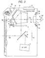
- Fig. 1 is a schematic view of the essential portions of Embodiment 1 not part of the present invention, where is applied to a single-lens reflex camera
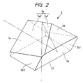
- Fig. 2 is an enlarged perspective view of the pentagonal prism of Fig. 1.
- the reference numeral 101 designates the body of a single-lens reflex camera.
- the reference numeral 100 denotes a mount for interchangeably mounting a phototaking lens, not shown, on the camera body 101
- the reference numeral 1 designates a quick return mirror adapted to be retracted out of an optical path when an object image is exposed on film (photosensitive surface) 12 and to direct an object light from the phototaking lens to a focusing screen 2 of a finder system during the other time.
- the quick return mirror 1 has a half mirror surface.
- the object image projected by the phototaking lens is formed on the focusing screen 2 via the mirror 1.
- the reference numeral 3 denotes an optical member for the erection of a finder image which is the object image on the focusing screen.
- the optical member 3 comprises a solid pentagonal prism as shown in Fig. 2.
- the definition of each surface of the pentagonal prism 3 will now be described with reference to Fig. 2.
- the surface 3a of the pentagonal prism 3 is a roof surface (roof mirror surface) formed by two reflecting surfaces 3a1 and 3a2 at an angle of 90°, surfaces 3b1 and 3b2 are right and left side walls, and a surface 3c is an exit surface for finder light, and provides an entrance surface for infrared light reflected from an eyeball 102, of infrared light emitted from light source means 5a-5d which will be described later, and in the present embodiment, the surface 3c is subjected to an anti-reflection coating against infrared light.
- a surface 3d is a non-functional surface
- a surface 3e is an inclined reflecting surface for making an optical axis fa of an eyepiece 4 and an optical axis 103 of the phototaking lens coincident with each other, and this surface reflects the visible light from the phototaking lens and transmits therethrough the infrared light reflected from the eyeball 102. That is, the surface 3e comprises a dichroic mirror (surface) for reflecting visible light and for transmitting infrared light therethrough.
- a surface 3f is an entrance surface for a light beam from the object image on the focusing screen 2 (the finder image).
- the reference numeral 4 designates an eyepiece, the opposite surfaces of which are provided with anti-reflection film against infrared light.
- Groups 5a, 5b, 5c and 5d are light source means emitting infrared light, and comprise a plurality of light emitting diodes (IRED's) 5a, 5b, 5c and 5d which are disposed around the eyepiece 4.
- the light source means 5a-5d illuminates the eyeball 102 of an observer observing a field of view of the finder with infrared light so that the image of the observer's pupil and a Purkinje's image formed by the reflected light on the surface of the cornea can be detected by a light receiving element 9 which will be described later.
- the reference numeral 6 denotes a mirror (an optical path bending mirror) which reflects the infrared reflected light from the eyeball 102 passed through the inclined reflecting surface 3e toward the optical axis 103 side of the phototaking lens which is below the camera body 101.
- the reference numeral 7 designates a stop
- the reference numeral 8 denotes a condensing (imaging) lens
- the reference numeral 9 designates the light receiving element (image sensor).
- design is made such that the infrared light passed through the inclined reflecting surface 3e is downwardly reflected by the mirror 6, and the elements 6, 7, 8 and 9 for visual axis detection are disposed in a space defined by a plane extended from the surface of the focusing screen 2 and the inclined reflecting surface 3e to thereby achieve the effective utilization of the space near the pentagonal prism, thus achieving the downsizing of the entire apparatus.
- the reference numeral 10 denotes a rotatable sub-mirror provided to the mirror 1 and directing a light beam passed through the light transmitting area (half mirror surface) of the mirror 1, of the light beam from the phototaking lens, to a conventional automatic focus detecting apparatus (AF apparatus) 11.
- the conventional AF apparatus 11 detects the in-focus state of the phototaking lens with respect to one or more distance measuring areas on the basis of visual axis information from the visual axis detecting means by a conventional detecting method.
- the reference numeral 13 designates the Xe tube of a strobe (lamp) contained in the camera body
- the reference numeral 14 denotes the reflector of the stroboscopic lamp
- the reference numeral 15 designates the front panel of the strobe
- the reference numeral 16 denotes the hinge shaft of the contained strobe.
- the reference numeral 17 designates an accessory shoe which is installed on the appear portion of the camera body 101 and on which an extraneous strobe (lamp) is mountable.
- a light beam from an object passed through the phototaking lens (not shown) is reflected by the quick return mirror 1 and forms an object image on or near the focal plane of the focusing screen 2.
- the light beam concerned with the object image formed on or near the focal plane of the focusing screen 2 is reflected by the roof surface 3a and inclined reflecting surface 3e of the pentagonal prism 3 and enters the photographer's eyeball 102 through the exit surface 3c and the eyepiece 4.
- the observer observes the erect image of the object (the finder image) formed on or near the focusing screen 2.
- a light beam passed through the quick return mirror 1 which is the half mirror enters the AF apparatus 11 via the sub-mirror 10.
- the in-focus state of the phototaking lens is detected by the use of the AF apparatus 11 with respect to a distance measuring area designated on the basis of the visual axis information from the visual axis detecting means, from among a plurality of distance measuring areas.
- the photographer half-depresses a release button, not shown, an infrared light is projected from some of the infrared light emitting diodes 5a to 5d to the photographer's eyeball 102.
- the infrared reflected light from the eyeball 102 passes through the eyepiece 4 having its opposite surfaces subjected to anti-reflection coating, the exit surface 3c of the pentagonal prism 3, the interior of the pentagonal prism 3 and the inclined reflecting surface 3e of the pentagonal prism 3 in succession and emerges out of the pentagonal prism 3 toward the front of the camera body.
- the infrared reflected light is then bent toward the optical axis 103 of the phototaking lens (downwardly) by the mirror 6 and forms an eyeball image on the sensor 9 for visual axis detection through the stop 7 and condensing lens 8 for visual axis detection.
- the visual axis position (visual axis information) of the photographer's eyeball 102 is detected on the basis of the output signal from the sensor 9 for visual axis detection.
- the sensor 9 use is made of a two-dimensional CCD or a two-dimensional light receiving element array of other type.
- the method of detecting the visual axis position may be a conventional one.
- the focusing lens of the phototaking lens is driven by the AF apparatus 11 so that the object image lying at the visual axis position in the finder field of view of the finder may be in focus, whereby focusing is effected.
- the release button When the photographer fully depresses the release button, the mirror 1 is retracted from the phototaking light beam and the sub-mirror 10 is also retracted from the phototaking light beam in operative association with the mirror 1.
- a shutter curtain not shown, is opened to thereby effect exposure on film 12.
- other phototaking operations e.g., automatic exposure adjustment, etc., than automatic focus adjustment can be effected by the use of the visual axis information.
- Fig. 3 is a schematic view of the essential portions of Embodiment 2 of the present invention
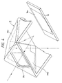
- Fig. 4 is an enlarged perspective view of the pentagonal prism of Fig. 3.
- Embodiment 2 differs from Embodiment 1 of Fig. 1 in that an optical member 31 for forming an erect image of an object image formed on the focusing screen (finder image) 2 is comprised of a hollow roof mirror, a reflecting member 18 comprising a plane parallel plate having an inclined reflecting surface 18a, and an aperture 31a for light emergence, and is the same as Embodiment 1 in the other points of construction and operation. Accordingly, these same points of construction and operation need not be described.
- the optical member 31 has a roof mirror (roof surface) 31b comprising two reflecting members 31b1 and 31b2 for reflecting a light beam from the object image on the screen 2 and converting it reversely into left and right beams, a reflecting member 18 having an inclined reflecting surface (effective reflecting surface) 18a which is the last reflecting surface inclined with respect to the finder optical axis fa to reflect the reflected light from the roof mirror 31b in the finder observation direction, and a transparent plane parallel plate 31a for light emergence of which the light entrance and exit surfaces are provided with anti-reflection film.
- a roof mirror (roof surface) 31b comprising two reflecting members 31b1 and 31b2 for reflecting a light beam from the object image on the screen 2 and converting it reversely into left and right beams
- a reflecting member 18 having an inclined reflecting surface (effective reflecting surface) 18a which is the last reflecting surface inclined with respect to the finder optical axis fa to reflect the reflected light from the roof mirror 31b in the finder observation direction
- the inclined reflecting 'surface 18a comprises a dichroic mirror (surface) for reflecting visible light and for transmitting infrared light therethrough.
- the reflecting member 18 is mounted in the front opening portion of the optical member 31.
- the roof mirror 31b (31b1 and 31b2) and the reflecting member 18 are constructed discretely from each other to thereby enable a dichroic film to be deposited by evaporation singly on the inclined reflecting surface 18a.
- the optical member 31 for erection of the finder image is made into the hollow pentagonal prism using the hollow roof mirror 31b and an inclined reflecting mirror 18 comprising a glass plate formed with deposited film having a dichroic mirror characteristic, whereby the following effects are obtained.
- the length of the optical path to the imaging lens of the optical system for visual axis detection as it is converted in terms of optical air can be secured greatly as compared with a solid pentagonal prism. Accordingly, when the imaging magnification on the light receiving element is made the same, the change in the imaging magnification by the displacement of the eye to be examined in the direction of the optical axis is small and highly accurate visual axis detection can be effected.
- the inclined reflecting mirror is provided by a glass plate which is a plane parallel plate and therefore, these aberrations are not much created and the take-out prism is unnecessary.
- the inclined reflecting surface is masked when silver is deposited by evaporation on the roof surface, and the other surface is masked when deposited film (dichroic film) having a dichroic mirror characteristic is formed on the inclined reflecting surface, and this is cumbersome.
- the deposition by evaporation of film having a dichroic mirror characteristic can be effected singly by the glass plate for the inclined reflecting mirror, and manufacture becomes easy.
- the present invention can adopt a construction in which a plane parallel plate is provided in lieu of the aperture 31a.
- anti-reflection coating is necessary for surfaces of the plane parallel plate, but there is the advantage that no dust comes into the hollow pentagonal prism.
- the eyeball of the observer looking into the field of view of the finder is illuminated with infrared light and the reflected infrared light from the eyeball is directed to the light receiving element through a portion of the optical member for the erection of the finder image and visual axis information is to be detected by the use of eyeball image information obtained from the output of the light receiving element, the elements such as the optical member for the erection of the finder image and the eyeball image detecting system are appropriately constructed, whereby there can be achieved a camera having visual axis detecting means for detecting visual axis information easily and highly accurately while the entire apparatus is simplified, thereby effecting various kinds of phototaking operations.
- design is made such that the reflected light passed through the inclined reflecting surface of the solid pentagonal prism or the inclined reflecting surface 18a of the reflecting mirror 18 is reflected toward the phototaking optical axis (downwardly) by the mirror 6 and is imaged on the light receiving element 9 and therefore, it becomes easy to dispose the contained stroboscopic lamp forwardly of the inclined reflecting surface of the solid pentagonal prism or the inclined reflecting surface of the reflecting mirror.
- other optical system can be disposed near it and therefore, the distance between the eyepiece and the mirror 6 can be set short, and the optical system can be made bright and accuracy can be heightened.
- any reduction in quantity of light and the creation of ghost can be prevented by providing anti-reflection coating not only on the opposite surfaces of the eyepiece but also on the surfaces of the other optical elements, and thus there is obtained the effect that a highly accurate visual axis detecting apparatus can be realized.
Landscapes
- Physics & Mathematics (AREA)
- General Physics & Mathematics (AREA)
- Viewfinders (AREA)
Claims (9)
- Ein optisches Gerät, mit:gekennzeichnet durch:einem Okular (4);einem Fokussierungsbildschirm (2), auf den ein Bild projiziert wird;eine Beleuchtungseinrichtung (5a bis 5d) zum Beleuchten eines Auges eines Benutzers mit Infrarotlicht;wobei das optische Abbildungssystem benachbart zu dem dichroitischen Spiegel in einem freien Teil der Reflektionseinrichtung hinter dem dichroitischen Spiegel bezüglich des Okulars angeordnet ist.eine Reflektionseinrichtung (31) einschließlich einer dachförmigen Spiegeloberfläche (31b) und eines flachen dichroitischen Spiegels (18a) zur Begrenzung eines hohlen Bereichs der Reflektionseinrichtung, wobei der dichroitische Spiegel einen Winkel bezüglich des Fokussierungsbildschirms aufweist, so dass er sichtbares Licht reflektiert und Infrarotlicht durchlässt, wobei die Reflektionseinrichtung darauf einfallendes Licht vom Fokussierungsbildschirm reflektiert, so dass das durch die dachförmige Spiegeloberfläche und den dichroitischen Spiegel reflektierte Licht in das Okular eintritt und ein Bild hierdurch betrachtbar ist, und wobei der dichroitische Spiegel der Reflektionseinrichtung von dem Auge des Benutzers reflektiertes und durch das Okular und den hohlen Bereich der Reflektionseinrichtung auf den dichroitischen Spiegel einfallendes Licht reflektiert;einem optischen Abbildungssystem (6, 7, 8), das durch das Okular und den dichroitischen Spiegel von dem Auge einfallendes Infrarotlicht empfängt und ein Bild des Auges unter Verwendung des vom Auge reflektierten Infrarotlichts bildet; wobei das optische Abbildungssystem einen Ablenkungsspiegel (6) zum Reflektieren von durch den dichroitischen Spiegel durchgelassenem Infrarotlicht von dem Auge, und eine Kondensatorlinse (8) aufweist zum Empfangen des Lichts des Spiegels (6);einer fotoelektrischen Umwandlungseinrichtung (9) zum Empfangen des Bilds des Auges von der Kondensatorlinse;
- Gerät nach Anspruch 1, wobei die fotoelektrische Umwandlungseinrichtung in der Ebene des Fokussierungsbildschirms liegt und das optische Abbildungssystem im Wesentlichen in dem freien Raum angeordnet ist, der zwischen der Rückseite des dichroitischen Spiegels und einer Verlängerung der Ebene des Fokussierungsbildschirms gebildet wird.
- Optisches Gerät nach Anspruch 1 oder 2, wobei die Beleuchtungseinrichtung in der Nähe des Okulars angeordnet ist.
- Optisches Gerät nach Anspruch 3, wobei die Beleuchtungseinrichtung eine Vielzahl von Leuchtdioden aufweist.
- Optisches Gerät nach einem der vorhergehenden Ansprüche, wobei der Spiegel (6) vorgesehen ist zum Ablenken des optischen Pfads des Lichts von dem Auge in Richtung der Seite der optischen Achse eines optischen Projektionssystems zur Projektion des Bilds auf die fotoelektrische Umwandlungseinrichtung (9).
- Optisches Gerät nach einem der vorherigen Ansprüche, wobei das Okular einen Antireflexionsfilm gegenüber Infrarotlicht aufweist.
- Optisches Gerät nach einem der vorhergehenden Ansprüche, wobei die Reflektionseinrichtung vorgesehen ist mit einer transparenten Platte in dem optischen Pfad des reflektierenden Lichts und dem ebenen Spiegel, und wobei das Licht von dem Auge durch die transparente Platte, den hohlen Bereich und den ebenen Spiegel in das optische Abbildungssystem eintritt.
- Optisches Gerät nach einem der Ansprüche 1 bis 8, wobei die Reflektionseinrichtung ein hohles Pentagonalprisma ist.
- Optisches Gerät nach einem der vorhergehenden Ansprüche, ferner mit einer Einrichtung zur Erfassung der Richtung der Sehachse des Auges und zum Verwenden des Ausgangssignals der fotoelektrischen Umwandlungseinrichtung, und einer Einrichtung zur Steuerung des optischen Geräts entsprechend dem Ergebnis der Erfassung der optischen Achse.
Applications Claiming Priority (6)
| Application Number | Priority Date | Filing Date | Title |
|---|---|---|---|
| JP3547796A JPH09211310A (ja) | 1996-01-30 | 1996-01-30 | カメラ |
| JP3547696 | 1996-01-30 | ||
| JP35477/96 | 1996-01-30 | ||
| JP3547796 | 1996-01-30 | ||
| JP35476/96 | 1996-01-30 | ||
| JP3547696A JPH09211309A (ja) | 1996-01-30 | 1996-01-30 | 視線検出手段を有したカメラ |
Publications (2)
| Publication Number | Publication Date |
|---|---|
| EP0793136A1 EP0793136A1 (de) | 1997-09-03 |
| EP0793136B1 true EP0793136B1 (de) | 2002-09-18 |
Family
ID=26374475
Family Applications (1)
| Application Number | Title | Priority Date | Filing Date |
|---|---|---|---|
| EP97300556A Expired - Lifetime EP0793136B1 (de) | 1996-01-30 | 1997-01-29 | Optische Geräte, wie ein Photoapparat |
Country Status (3)
| Country | Link |
|---|---|
| US (1) | US6052533A (de) |
| EP (1) | EP0793136B1 (de) |
| DE (1) | DE69715488T2 (de) |
Families Citing this family (1)
| Publication number | Priority date | Publication date | Assignee | Title |
|---|---|---|---|---|
| JP4974780B2 (ja) * | 2007-06-22 | 2012-07-11 | キヤノン株式会社 | 光学観察装置及び撮像装置 |
Citations (1)
| Publication number | Priority date | Publication date | Assignee | Title |
|---|---|---|---|---|
| DE4037908A1 (de) * | 1989-11-30 | 1991-06-06 | Asahi Optical Co Ltd | Blickrichtung-erfassungsgeraet |
Family Cites Families (11)
| Publication number | Priority date | Publication date | Assignee | Title |
|---|---|---|---|---|
| JPS5039128A (de) * | 1973-08-09 | 1975-04-11 | ||
| JPH0241613Y2 (de) * | 1979-02-01 | 1990-11-06 | ||
| JPS6161135A (ja) * | 1984-09-03 | 1986-03-28 | Omron Tateisi Electronics Co | 自動焦点調整カメラ |
| JPH0318520U (de) * | 1989-07-03 | 1991-02-22 | ||
| US5260734A (en) * | 1989-11-30 | 1993-11-09 | Asahi Kogaku Kogyo Kabushiki Kaisha | Determining a direction in which an eye gazes |
| US5245374A (en) * | 1990-12-04 | 1993-09-14 | Asahi Kogaku Kogyo Kabushiki Kaisha | Camera having strobe incorporated therein |
| JPH05107604A (ja) * | 1991-12-18 | 1993-04-30 | Minolta Camera Co Ltd | カメラ |
| JPH05107595A (ja) * | 1991-12-18 | 1993-04-30 | Minolta Camera Co Ltd | カメラ装置 |
| DE4330265B4 (de) * | 1992-09-07 | 2004-07-29 | Canon K.K. | Vorrichtung zum Erfassen der Sehachse eines Auges einer ein optisches Gerät bedienenden Person |
| JPH0720537A (ja) * | 1993-07-05 | 1995-01-24 | Canon Inc | 一眼レフカメラのファインダー装置 |
| JPH07333689A (ja) * | 1994-06-14 | 1995-12-22 | Canon Inc | 観察装置及び該観察装置を備えるカメラ |
-
1997
- 1997-01-24 US US08/788,292 patent/US6052533A/en not_active Expired - Fee Related
- 1997-01-29 DE DE69715488T patent/DE69715488T2/de not_active Expired - Lifetime
- 1997-01-29 EP EP97300556A patent/EP0793136B1/de not_active Expired - Lifetime
Patent Citations (1)
| Publication number | Priority date | Publication date | Assignee | Title |
|---|---|---|---|---|
| DE4037908A1 (de) * | 1989-11-30 | 1991-06-06 | Asahi Optical Co Ltd | Blickrichtung-erfassungsgeraet |
Also Published As
| Publication number | Publication date |
|---|---|
| HK1002774A1 (en) | 1998-09-18 |
| DE69715488T2 (de) | 2003-02-27 |
| US6052533A (en) | 2000-04-18 |
| EP0793136A1 (de) | 1997-09-03 |
| DE69715488D1 (de) | 2002-10-24 |
Similar Documents
| Publication | Publication Date | Title |
|---|---|---|
| US5245371A (en) | Camera provided with a visual axis direction detecting portion | |
| US5214466A (en) | Camera having visual axis detecting apparatus | |
| US4572627A (en) | Eye fundus camera | |
| US5526083A (en) | Finder system of a camera | |
| US5761543A (en) | Apparatus for measuring anterior eye portion | |
| US5784656A (en) | Camera with light dividing devices | |
| JPH01277533A (ja) | 視線検出装置 | |
| EP0793136B1 (de) | Optische Geräte, wie ein Photoapparat | |
| US5576796A (en) | Optical apparatus having function to detect visual axis | |
| HK1002774B (en) | Optical apparatus such as a camera | |
| US6097892A (en) | Viewfinder system and optical apparatus having the same | |
| JPH09211310A (ja) | カメラ | |
| US5426483A (en) | Camera with a line of sight detecting device | |
| JP3184542B2 (ja) | カメラ | |
| US4428653A (en) | Mirror reflex camera with an electronic range finder | |
| JP3272634B2 (ja) | カメラのファインダー装置 | |
| JPH06148511A (ja) | 視線検出装置及びそれを有した光学装置 | |
| JP3272636B2 (ja) | カメラのファインダー装置 | |
| JPH09211309A (ja) | 視線検出手段を有したカメラ | |
| JP3272635B2 (ja) | カメラのファインダー装置 | |
| JPH03107909A (ja) | 視線検出装置 | |
| JP2756413B2 (ja) | 視線検出装置を備える光学装置 | |
| JPH07333689A (ja) | 観察装置及び該観察装置を備えるカメラ | |
| JPS63229439A (ja) | 自動焦点整合装置 | |
| JPH06138374A (ja) | 視線検出装置を有する光学装置 |
Legal Events
| Date | Code | Title | Description |
|---|---|---|---|
| PUAI | Public reference made under article 153(3) epc to a published international application that has entered the european phase |
Free format text: ORIGINAL CODE: 0009012 |
|
| AK | Designated contracting states |
Kind code of ref document: A1 Designated state(s): DE FR GB |
|
| 17P | Request for examination filed |
Effective date: 19980114 |
|
| 17Q | First examination report despatched |
Effective date: 20000215 |
|
| GRAG | Despatch of communication of intention to grant |
Free format text: ORIGINAL CODE: EPIDOS AGRA |
|
| GRAG | Despatch of communication of intention to grant |
Free format text: ORIGINAL CODE: EPIDOS AGRA |
|
| GRAH | Despatch of communication of intention to grant a patent |
Free format text: ORIGINAL CODE: EPIDOS IGRA |
|
| GRAH | Despatch of communication of intention to grant a patent |
Free format text: ORIGINAL CODE: EPIDOS IGRA |
|
| GRAA | (expected) grant |
Free format text: ORIGINAL CODE: 0009210 |
|
| AK | Designated contracting states |
Kind code of ref document: B1 Designated state(s): DE FR GB |
|
| REG | Reference to a national code |
Ref country code: GB Ref legal event code: FG4D |
|
| REF | Corresponds to: |
Ref document number: 69715488 Country of ref document: DE Date of ref document: 20021024 |
|
| ET | Fr: translation filed | ||
| PLBE | No opposition filed within time limit |
Free format text: ORIGINAL CODE: 0009261 |
|
| STAA | Information on the status of an ep patent application or granted ep patent |
Free format text: STATUS: NO OPPOSITION FILED WITHIN TIME LIMIT |
|
| 26N | No opposition filed |
Effective date: 20030619 |
|
| PGFP | Annual fee paid to national office [announced via postgrant information from national office to epo] |
Ref country code: FR Payment date: 20110209 Year of fee payment: 15 Ref country code: DE Payment date: 20110131 Year of fee payment: 15 |
|
| PGFP | Annual fee paid to national office [announced via postgrant information from national office to epo] |
Ref country code: GB Payment date: 20110125 Year of fee payment: 15 |
|
| GBPC | Gb: european patent ceased through non-payment of renewal fee |
Effective date: 20120129 |
|
| REG | Reference to a national code |
Ref country code: FR Ref legal event code: ST Effective date: 20120928 |
|
| PG25 | Lapsed in a contracting state [announced via postgrant information from national office to epo] |
Ref country code: GB Free format text: LAPSE BECAUSE OF NON-PAYMENT OF DUE FEES Effective date: 20120129 Ref country code: DE Free format text: LAPSE BECAUSE OF NON-PAYMENT OF DUE FEES Effective date: 20120801 |
|
| REG | Reference to a national code |
Ref country code: DE Ref legal event code: R119 Ref document number: 69715488 Country of ref document: DE Effective date: 20120801 |
|
| PG25 | Lapsed in a contracting state [announced via postgrant information from national office to epo] |
Ref country code: FR Free format text: LAPSE BECAUSE OF NON-PAYMENT OF DUE FEES Effective date: 20120131 |