EP0793034A2 - Dispositif d'accouplement à auto-maintien - Google Patents
Dispositif d'accouplement à auto-maintien Download PDFInfo
- Publication number
- EP0793034A2 EP0793034A2 EP97102978A EP97102978A EP0793034A2 EP 0793034 A2 EP0793034 A2 EP 0793034A2 EP 97102978 A EP97102978 A EP 97102978A EP 97102978 A EP97102978 A EP 97102978A EP 0793034 A2 EP0793034 A2 EP 0793034A2
- Authority
- EP
- European Patent Office
- Prior art keywords
- armature
- magnetic
- magnetic flux
- brake
- connecting device
- Prior art date
- Legal status (The legal status is an assumption and is not a legal conclusion. Google has not performed a legal analysis and makes no representation as to the accuracy of the status listed.)
- Granted
Links
- 230000004907 flux Effects 0.000 claims abstract description 31
- 238000005299 abrasion Methods 0.000 abstract description 4
- 230000007423 decrease Effects 0.000 abstract description 4
- BGPVFRJUHWVFKM-UHFFFAOYSA-N N1=C2C=CC=CC2=[N+]([O-])C1(CC1)CCC21N=C1C=CC=CC1=[N+]2[O-] Chemical compound N1=C2C=CC=CC2=[N+]([O-])C1(CC1)CCC21N=C1C=CC=CC1=[N+]2[O-] BGPVFRJUHWVFKM-UHFFFAOYSA-N 0.000 description 9
- 238000010276 construction Methods 0.000 description 3
- 239000002184 metal Substances 0.000 description 3
- 230000002411 adverse Effects 0.000 description 2
- 238000003754 machining Methods 0.000 description 2
- 239000000470 constituent Substances 0.000 description 1
Images


Classifications
-
- H—ELECTRICITY
- H02—GENERATION; CONVERSION OR DISTRIBUTION OF ELECTRIC POWER
- H02K—DYNAMO-ELECTRIC MACHINES
- H02K7/00—Arrangements for handling mechanical energy structurally associated with dynamo-electric machines, e.g. structural association with mechanical driving motors or auxiliary dynamo-electric machines
- H02K7/10—Structural association with clutches, brakes, gears, pulleys or mechanical starters
- H02K7/108—Structural association with clutches, brakes, gears, pulleys or mechanical starters with friction clutches
- H02K7/1085—Magnetically influenced friction clutches
-
- F—MECHANICAL ENGINEERING; LIGHTING; HEATING; WEAPONS; BLASTING
- F16—ENGINEERING ELEMENTS AND UNITS; GENERAL MEASURES FOR PRODUCING AND MAINTAINING EFFECTIVE FUNCTIONING OF MACHINES OR INSTALLATIONS; THERMAL INSULATION IN GENERAL
- F16D—COUPLINGS FOR TRANSMITTING ROTATION; CLUTCHES; BRAKES
- F16D27/00—Magnetically- or electrically- actuated clutches; Control or electric circuits therefor
- F16D27/10—Magnetically- or electrically- actuated clutches; Control or electric circuits therefor with an electromagnet not rotating with a clutching member, i.e. without collecting rings
- F16D27/108—Magnetically- or electrically- actuated clutches; Control or electric circuits therefor with an electromagnet not rotating with a clutching member, i.e. without collecting rings with axially movable clutching members
- F16D27/112—Magnetically- or electrically- actuated clutches; Control or electric circuits therefor with an electromagnet not rotating with a clutching member, i.e. without collecting rings with axially movable clutching members with flat friction surfaces, e.g. discs
-
- F—MECHANICAL ENGINEERING; LIGHTING; HEATING; WEAPONS; BLASTING
- F16—ENGINEERING ELEMENTS AND UNITS; GENERAL MEASURES FOR PRODUCING AND MAINTAINING EFFECTIVE FUNCTIONING OF MACHINES OR INSTALLATIONS; THERMAL INSULATION IN GENERAL
- F16D—COUPLINGS FOR TRANSMITTING ROTATION; CLUTCHES; BRAKES
- F16D55/00—Brakes with substantially-radial braking surfaces pressed together in axial direction, e.g. disc brakes
- F16D55/02—Brakes with substantially-radial braking surfaces pressed together in axial direction, e.g. disc brakes with axially-movable discs or pads pressed against axially-located rotating members
-
- H—ELECTRICITY
- H02—GENERATION; CONVERSION OR DISTRIBUTION OF ELECTRIC POWER
- H02K—DYNAMO-ELECTRIC MACHINES
- H02K7/00—Arrangements for handling mechanical energy structurally associated with dynamo-electric machines, e.g. structural association with mechanical driving motors or auxiliary dynamo-electric machines
- H02K7/10—Structural association with clutches, brakes, gears, pulleys or mechanical starters
- H02K7/102—Structural association with clutches, brakes, gears, pulleys or mechanical starters with friction brakes
- H02K7/1021—Magnetically influenced friction brakes
- H02K7/1023—Magnetically influenced friction brakes using electromagnets
- H02K7/1025—Magnetically influenced friction brakes using electromagnets using axial electromagnets with generally annular air gap
-
- F—MECHANICAL ENGINEERING; LIGHTING; HEATING; WEAPONS; BLASTING
- F16—ENGINEERING ELEMENTS AND UNITS; GENERAL MEASURES FOR PRODUCING AND MAINTAINING EFFECTIVE FUNCTIONING OF MACHINES OR INSTALLATIONS; THERMAL INSULATION IN GENERAL
- F16D—COUPLINGS FOR TRANSMITTING ROTATION; CLUTCHES; BRAKES
- F16D55/00—Brakes with substantially-radial braking surfaces pressed together in axial direction, e.g. disc brakes
- F16D2055/0004—Parts or details of disc brakes
- F16D2055/0058—Fully lined, i.e. braking surface extending over the entire disc circumference
-
- F—MECHANICAL ENGINEERING; LIGHTING; HEATING; WEAPONS; BLASTING
- F16—ENGINEERING ELEMENTS AND UNITS; GENERAL MEASURES FOR PRODUCING AND MAINTAINING EFFECTIVE FUNCTIONING OF MACHINES OR INSTALLATIONS; THERMAL INSULATION IN GENERAL
- F16D—COUPLINGS FOR TRANSMITTING ROTATION; CLUTCHES; BRAKES
- F16D2121/00—Type of actuator operation force
- F16D2121/18—Electric or magnetic
- F16D2121/20—Electric or magnetic using electromagnets
-
- F—MECHANICAL ENGINEERING; LIGHTING; HEATING; WEAPONS; BLASTING
- F16—ENGINEERING ELEMENTS AND UNITS; GENERAL MEASURES FOR PRODUCING AND MAINTAINING EFFECTIVE FUNCTIONING OF MACHINES OR INSTALLATIONS; THERMAL INSULATION IN GENERAL
- F16D—COUPLINGS FOR TRANSMITTING ROTATION; CLUTCHES; BRAKES
- F16D2129/00—Type of operation source for auxiliary mechanisms
- F16D2129/06—Electric or magnetic
- F16D2129/065—Permanent magnets
Definitions
- the present invention relates to a self holding type connecting device, more specifically, a self holding type braking device which is connected to a rotating body and which brakes rotation of the rotating body, or a self holding type clutch device which is connected to a rotating body and which transmits rotation of the rotating body to another rotating body.
- the braking operation will be released. Contrary to this, if generation of the electro-magnetic force is cut down due to breakage of the solenoid coil or power source trouble, the braking device continues the braking condition.
- a brake pad is made in contact with the rotating body by means of mechanical force generated by the spring so as to generate braking force. If the brake pad is abraded, the extension of the spring increases, and accordingly, the pressing force of the spring decreases. As a result, the braking force is reduced.
- a self holding type connecting device comprising an armature which is disposed movably in an axial direction, a magnetic path member having a cross section formed along a closed loop and having an axial space wherein axial movement of the armature is permitted, a permanent magnet secured to the magnetic path member and forming two kinds of magnetic flux which pass through the armature and the magnetic path member, an electric magnetic coil which forms magnetic flux for moving the armature in an axial direction against the two kinds of magnetic flux, and means for switching direction of the magnetic flux from the electric magnetic coil.
- the armature may be so constructed that it is movable in an axial direction and is unable to rotate, whereby the armature constitutes an electro-magnetic brake for braking a rotating body. Further, the armature may be so constructed that it is movable in an axial direction and is rotatable, whereby the armature constitutes an electro-magnetic clutch for transmitting rotation between the rotating bodies.
- the rotating body may be secured to a spindle of a motor whereby a brake motor or a motor provided with a clutch is constituted.
- the braking or clutching conditions (operating/non-operating) do not change incidentally due to trouble of the parts constituting the brake or clutch, and safety of the system is highly increased.
- the amount of the air gap decrease when a brake pad is abraded decreases, as a result, the attracting force, and accordingly, the braking force, is increased.
- the performance is not adversely influenced even when the abrasion occurs. If a stop is disposed at a predetermined position within the air gap, the pressing force (braking force) during the braking condition and the holding force during the non-operating condition can be set at will.
- the self holding type electro magnetic braking device comprises an armature 1 which is disposed movably in an axial direction (horizontally on the sheet wherein Fig. 1 is illustrated) and is unable to rotate about the axis, a magnetic path member 2 for passing magnetic flux therethrough having a cross section formed in a C-shape as illustrated in a cross sectional view in Fig. 1 and having a small space wherein axial movement of the armature 1 is permitted, an electro-magnetic coil 3 accommodated in the space of the magnetic path member 2, a permanent magnet 4 secured to the outside of the armature 1, and non-magnetic members 5 and 5 disposed at both the sides of the permanent magnet 4.
- the armature 1 has a brake pad 6 secured to the right side thereof, and when the armature 1 moves within the open space 2a of the magnetic path member 2 as illustrated in Fig. 1 so as to be pressed against a rotor 7 which is connected to an output spindle of a motor (not illustrated in Fig. 1), the braking operation is performed.
- the magnetic resistances of the air gaps 9a and 9b which are formed in the open space 2a between the ends of the magnetic path member 2 and the armature 1, respectively, are proportional to the lengths of the air gaps 9a and 9b, respectively.
- the attracting forces exerted on the armature 1 through the air gaps 9a and 9b are proportional to the reciprocals of the magnetic resistances of air gaps 9a and 9b, respectively.
- the lengths of the air gaps 9a and 9b in the following explanation are only for example, and they may be outside the exemplified range depending on the amount of stroke of the brake, the size of the brake and so on.
- the electric coil 3 is supplied with current and the armature 1 is moved toward the rotor 7 so as to be in a condition illustrated in Fig. 1.
- the equivalent magnetic circuit under this condition is illustrated in Fig. 2.
- the air gaps 9a and 9b vary, for example, the left air gap 9a becomes 4 to 6 mm and is larger than the right air gap 9b, which is 0 to 2 mm.
- the resistance of the magnetic path R1 becomes larger than that R2.
- the magnetic flux ⁇ 1 becomes smaller than that ⁇ 2
- the attracting force F2 which is exerted in the air gap 9b becomes larger than that F1 which is exerted in the air gap 9a.
- the armature 1 is moved axially, to the right in Fig. 1, the armature 1 is kept to be pressed against the rotor 7 due to the difference in the attracting forces, i.e., the holding force, which is equal to the amount F2 minus F1.
- the magnetic flux ⁇ 1 is smaller than that ⁇ 2, and the attracting force F2 is larger than that F1.
- F2 the attracting force
- this movement of the armature 1 is performed by the electro-magnetic coil 3.
- the equivalent magnetic circuit upon transfer of the brake condition from the operating condition to the non-operating condition is illustrated in Fig. 3. It is necessary to generate the magnetic flux ⁇ by the electro-magnetic coil 3, which flux directs as illustrated in Fig. 3.
- the armature 1 moves in a direction opposite to that described above, i.e., in a direction wherein the armature separates from the rotor 7. Accordingly, the brake becomes in a non-operating condition.
- FIG. 4 The cross sectional view and the equivalent magnetic circuit under the condition wherein the brake is in a non-operating condition are illustrated in Figs. 4 and 5, respectively. More specifically, the left air gap 9a' becomes to a an amount, for example, between 0 and 2 mm and is smaller than the right air gap 9b' which is for example 4 to 6 mm, and the magnetic resistance R2' becomes larger than R1', the magnetic flux ⁇ 2' becomes smaller than ⁇ 1.
- the relationship between the attracting forces in the air gasps 9a' and 9b' is such that the attracting force F1' which is exerted in the air gap 9a' is larger than that F2' which is exerted in the air gap 9b'.
- the armature 1 is kept in a condition wherein it is separated from the rotor 7 due to the difference in the attracting forces, i.e., the holding force, which is equal to the amount F1' minus F2'.
- the electro-magnetic coil 3 generates the magnetic flux ⁇ ', the combined magnetic flux ( ⁇ 1' minus ⁇ ') being smaller than that ( ⁇ 2' plus ⁇ '), in a direction opposite to that described above, the armature 1 moves in an opposite direction toward the rotor 7. Accordingly, the brake becomes in an operating condition.
- a switch is used to control the generation of magnetic flux by the electro-magnetic coil 3 and control the generating direction of the magnetic flux ⁇ and ⁇ ' by changing the polarities of the electric voltages supplied with the two wires connected to the electro-magnetic coil 3 so as to change the generating directions of the magnetic flux ⁇ and ⁇ ' by the electro-magnetic coil 3.
- the present invention includes a switch for switching the generation and direction of the the magnetic flux by the electro-magnetic coil 3.
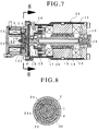
- Fig. 7 shows a brake motor wherein the present invention is carried out.
- the right half portion in Fig. 7 constitutes a brushless motor, and an electro-magnetic brake according to the present invention is disposed at the left half in Fig. 7.
- a motor according to the present invention is not limited to that illustrated herein and may be of any conventionally known type. The illustrated embodiment will now be briefly explained.
- a shaft 13 is rotatably supported in a case 11 by means of a pair of bearings 12 and 12.
- the shaft 13 has an output member, for example, a gear wheel 25, at the right end thereof, so as to take out output of the motor through the gear wheel 25.
- the shaft 13 has permanent magnets 14 secured at the center thereof which magnets serve as a rotor.
- An electric magnet 15, which is provided with coil and which will serve as a stator, is disposed in such a manner that it faces to the rotor 14 forming a small clearance therebetween.
- the shaft 13 has a small permanent magnet 16 at the left end thereof, which magnet is used to detect the rotation of the shaft 13.
- a hole IC 17 is disposed in such a manner that it faces the permanent magnet 16. The phase of the magnetic poles of the rotor 14 is detected by the permanent magnet 16 and the hole IC 17 so as to control current supply to the coil of the rotor 14.
- the shaft 13 has a disc brake rotor 19 formed in a circular and secured to the left end thereof by means of a lock screw 18.
- a brake rotor 21 which is similarly formed in a circular disc is disposed so that it faces to the circular brake rotor 19 of the shaft 13. Both of or either one of the brake rotors 19 and 21 have brake pads 6 attached thereto.
- a shaft 22 projecting from the brake rotor 21 has a circular disc 1 having a small diameter and secured thereto by means of a nut 20.
- the circular disc 1 serves as the armature of the present invention.
- the brake rotor 21, the shaft 22 and the armature 1 are able to move in an axial direction as a whole but are unable to rotate about the axis.
- a permanent magnet 4 is disposed in such a manner that it faces the armature 1.
- a magnetic path member 2 having a C-cross section is disposed in such a manner that its ends sandwiches the small circular disc portion of the armature 1.
- the magnetic path member 2 has a permanent magnet 4 secured thereto and is so constructed that two sets of magnetic flux generated from the permanent magnet 4 pass through the armature 1, respectively.
- Small air gaps 9a and 9b are formed between the small circular disc portion of the armature 1 and the ends of the magnetic path member 2, respectively.
- the armature 1 is moved axially along the permanent magnet 4 in this embodiment.
- a metal member 23 which has a good machining ability and excellent strength is integrally disposed within the inner portion of the permanent magnet 4.
- the metal member 23 has three recesses 23a for supporting roller guides 24 at the periphery thereof as illustrated in Fig. 8.
- the roller guides 24 guide the mutual movement in an axial direction between the metal guide member 23 and the armature 1.
- projections and depression which are engage with each other so as to prohibit their mutual rotation, are formed at the periphery of the brake rotor which has a large diameter of the armature and the inner surface of the case 11, respectively, so that the armature 1 itself can move in an axial direction for a small distance so as to serve as an electro-magnetic braking device which brakes the rotation of the motor and so that it does not rotate about the axis.
- the magnetic flux is controlled by the permanent magnet and the coil disposed at the left of the permanent magnet.
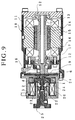
- the present invention may be applied for a clutch device if the armature is movable in an axial direction and is rotatable about an axis.
- An example of such a clutch example is illustrated in Fig. 9.
- the output of the motor is taken out and shut off. Accordingly, the brake rotors 19 and 21 and brake pads 6 which were described with reference to the previous embodiment are replaced with clutch rotors 19 and 21 and clutch pads 6 in this embodiment. Further, this embodiment differs from the above-described embodiment in that not only the clutch rotor 21, the shaft 22 and the armature 1 are as a whole movable in an axial direction, but also they are rotatable about the axis. However, the constructions of the constituting parts are substantially the same.
- the output member such as the gear wheel 25 was disposed at the shaft 13 in the above-described embodiment, an output member such as a gear wheel 25 is coupled to the shaft 22 of the clutch by means of spline 24, and the clutch rotor 21, the shaft 22 and the armature 1 are moveable in an axial direction regardless of the gear wheel 25. Since the remaining constructions are similar to those of the above-described embodiment, further explanation therefor will be omitted.
- the present invention achieves the following advantages.
Landscapes
- Engineering & Computer Science (AREA)
- General Engineering & Computer Science (AREA)
- Physics & Mathematics (AREA)
- Electromagnetism (AREA)
- Mechanical Engineering (AREA)
- Power Engineering (AREA)
- Braking Arrangements (AREA)
- Electromagnets (AREA)
Applications Claiming Priority (3)
| Application Number | Priority Date | Filing Date | Title |
|---|---|---|---|
| JP8065485A JPH09229105A (ja) | 1996-02-27 | 1996-02-27 | 自己保持型連結装置 |
| JP65485/96 | 1996-02-27 | ||
| JP6548596 | 1996-02-27 |
Publications (3)
| Publication Number | Publication Date |
|---|---|
| EP0793034A2 true EP0793034A2 (fr) | 1997-09-03 |
| EP0793034A3 EP0793034A3 (fr) | 1999-04-07 |
| EP0793034B1 EP0793034B1 (fr) | 2001-10-04 |
Family
ID=13288458
Family Applications (1)
| Application Number | Title | Priority Date | Filing Date |
|---|---|---|---|
| EP97102978A Expired - Lifetime EP0793034B1 (fr) | 1996-02-27 | 1997-02-24 | Dispositif d'accouplement à auto-maintien |
Country Status (4)
| Country | Link |
|---|---|
| US (1) | US5847478A (fr) |
| EP (1) | EP0793034B1 (fr) |
| JP (1) | JPH09229105A (fr) |
| DE (1) | DE69707030T2 (fr) |
Cited By (10)
| Publication number | Priority date | Publication date | Assignee | Title |
|---|---|---|---|---|
| WO1999042738A1 (fr) * | 1998-02-21 | 1999-08-26 | Rover Group Limited | Mecanisme d'embrayage |
| FR2786334A1 (fr) * | 1998-11-20 | 2000-05-26 | Mitsubishi Electric Corp | Stator de generateur alternatif destine a etre utilise dans un vehicule et procede de fabrication de celui-ci |
| WO2003104671A1 (fr) * | 2002-06-10 | 2003-12-18 | Valeo Sicherheitssysteme Gmbh | Embrayage electromagnetique a friction et procede d'utilisation |
| WO2007085348A1 (fr) * | 2006-01-25 | 2007-08-02 | Getrag Innovations Gmbh | Systeme de transmission a plusieurs rapports pour transmission de vehicule automobile et procede d'entree et de sortie dans un rapport de transmission |
| WO2007130421A3 (fr) * | 2006-05-01 | 2008-04-10 | Danaher Motion | Dispositif de freinage ou d'embrayage |
| EP2143677A1 (fr) * | 2008-07-09 | 2010-01-13 | Sagem Communications Sas | Dispositif de traitement de feuilles comportant un rouleau d'entraînement et des moyens de maintien de ce rouleau dans une position de repos |
| EP2514644A3 (fr) * | 2011-04-19 | 2013-05-29 | Robert Bosch GmbH | Dispositif de verrouillage, en particulier pour verrouillage du volant |
| EP2241777A3 (fr) * | 2009-04-17 | 2013-07-24 | LICOS Trucktec GmbH | Couplage à bascule |
| WO2022122514A1 (fr) * | 2020-12-10 | 2022-06-16 | Safran Landing Systems | Actionneur a frein de parking integre |
| WO2024188585A1 (fr) * | 2023-03-14 | 2024-09-19 | Sew-Eurodrive Gmbh & Co. Kg | Ensemble frein, en particulier pour un moteur électrique, pour freiner un arbre |
Families Citing this family (21)
| Publication number | Priority date | Publication date | Assignee | Title |
|---|---|---|---|---|
| DE19752543A1 (de) * | 1997-11-27 | 1999-06-02 | Bosch Gmbh Robert | Magnetbremse und elektromechanische Bremsvorrichtung mit einer Magnetbremse |
| US6581739B1 (en) * | 2000-10-31 | 2003-06-24 | Eaton Corporation | Lightweight magnetic particle device |
| US6619453B2 (en) | 2001-12-14 | 2003-09-16 | Eaton Corporation | Electromagnetic mechanical particle clutch |
| US6640563B2 (en) * | 2002-01-10 | 2003-11-04 | Dayco Products, Llc | Momentary engagement and disengagement of automotive air conditioner clutch |
| JP2005009633A (ja) * | 2003-06-20 | 2005-01-13 | Tokico Ltd | 電動ブレーキ装置 |
| US20050110353A1 (en) * | 2003-11-26 | 2005-05-26 | Kramer Dennis A. | Traction motor with disc brake rotor |
| EP1848898B1 (fr) * | 2005-02-15 | 2008-04-16 | Kendrion Binder Magnete GmbH | Frein electromagnetique comportant un aimant permanent |
| JP5422566B2 (ja) * | 2007-12-10 | 2014-02-19 | オーチス エレベータ カンパニー | 制動力を印加する永久磁石バイアスを有するエレベータブレーキ装置 |
| DE102010012610A1 (de) * | 2010-03-24 | 2011-09-29 | Hoerbiger Antriebstechnik Gmbh | Schaltbare Magnetkupplung und Verfahren zum Betätigen einer schaltbaren Magnetkupplung |
| GB201013576D0 (en) * | 2010-08-12 | 2010-09-29 | Microtecnica Actuation Tech Ltd | Electromagnetic brake or clutch and method of operation |
| US9249845B2 (en) * | 2013-04-29 | 2016-02-02 | Licos Trucktec Gmbh | Friction switch coupling |
| CN104363979A (zh) * | 2013-11-14 | 2015-02-18 | 株式会社Tbk | 电磁型制动器 |
| CN103818234B (zh) * | 2014-03-11 | 2016-08-17 | 吉林大学 | 带有薄型无励磁式电磁驻车制动装置的分体式电动轮系统 |
| FR3018880B1 (fr) * | 2014-03-24 | 2017-08-25 | Messier Bugatti Dowty | Actionneur electromecanique de frein a blocage de parc pour aeronef |
| EP3139494A4 (fr) | 2014-04-16 | 2017-12-20 | TBK Co., Ltd. | Système de moteur à résonance |
| US9308990B2 (en) * | 2014-05-30 | 2016-04-12 | Goodrich Corporation | Voice coil linear activated park brake |
| JP6492671B2 (ja) * | 2015-01-13 | 2019-04-03 | シンフォニアテクノロジー株式会社 | 動力伝達装置 |
| CN107725646B (zh) * | 2017-09-11 | 2019-04-23 | 浙江零跑科技有限公司 | 一种新能源车用齿轮式制动执行装置 |
| US10767718B2 (en) | 2019-01-15 | 2020-09-08 | Warner Electric Technology Llc | Rotational coupling device with armature release collar |
| JP2019108986A (ja) * | 2019-02-28 | 2019-07-04 | シンフォニアテクノロジー株式会社 | 動力伝達装置 |
| JP7394455B2 (ja) * | 2020-03-31 | 2023-12-08 | 東京モートロニクス株式会社 | モータ |
Citations (5)
| Publication number | Priority date | Publication date | Assignee | Title |
|---|---|---|---|---|
| US3642104A (en) * | 1968-08-22 | 1972-02-15 | Wolfgang Schafer | Electric couplings with permanent magnet |
| DE2460121A1 (de) * | 1974-12-19 | 1976-06-24 | Engel Gmbh | Haltebremse |
| JPH01303331A (ja) * | 1988-05-31 | 1989-12-07 | Shinko Electric Co Ltd | 電磁ブレーキ |
| US5185542A (en) * | 1991-08-28 | 1993-02-09 | Electroid Company | Electromagnetic pulse operated bi-stable brake |
| EP0693633A2 (fr) * | 1994-07-22 | 1996-01-24 | Ti Matrix Engineering Limited | Frein à aimant permanent avec contrÔle électromagnétique |
Family Cites Families (8)
| Publication number | Priority date | Publication date | Assignee | Title |
|---|---|---|---|---|
| US3730317A (en) * | 1971-07-21 | 1973-05-01 | Eaton Corp | Electromagnetic coupling with permanent magnets |
| US4496922A (en) * | 1983-12-05 | 1985-01-29 | Warner Electric Brake & Clutch Company | Electromagnetically released coupling |
| WO1988002946A1 (fr) * | 1986-10-17 | 1988-04-21 | Mitsubishi Denki Kabushiki Kaisha | Demarreur pour moteur |
| JPH02246766A (ja) * | 1989-03-16 | 1990-10-02 | Mitsubishi Electric Corp | 電磁ブレーキ装置 |
| US5121018A (en) * | 1991-03-04 | 1992-06-09 | Lucas Aerospace Power Equipment Corporation | Latching brake using permanent magnet |
| US5119918A (en) * | 1991-10-11 | 1992-06-09 | Dana Corporation | Electromagnetic clutch with permanent magnet brake |
| US5172798A (en) * | 1992-06-08 | 1992-12-22 | Easom Engineering And Manufacturing Corporation | Electrical actuation system for a drive |
| GB9302623D0 (en) * | 1993-02-10 | 1993-03-24 | Ti Matrix Eng Ltd | Brake device |
-
1996
- 1996-02-27 JP JP8065485A patent/JPH09229105A/ja not_active Abandoned
-
1997
- 1997-02-24 DE DE69707030T patent/DE69707030T2/de not_active Expired - Fee Related
- 1997-02-24 EP EP97102978A patent/EP0793034B1/fr not_active Expired - Lifetime
- 1997-02-26 US US08/805,622 patent/US5847478A/en not_active Expired - Fee Related
Patent Citations (5)
| Publication number | Priority date | Publication date | Assignee | Title |
|---|---|---|---|---|
| US3642104A (en) * | 1968-08-22 | 1972-02-15 | Wolfgang Schafer | Electric couplings with permanent magnet |
| DE2460121A1 (de) * | 1974-12-19 | 1976-06-24 | Engel Gmbh | Haltebremse |
| JPH01303331A (ja) * | 1988-05-31 | 1989-12-07 | Shinko Electric Co Ltd | 電磁ブレーキ |
| US5185542A (en) * | 1991-08-28 | 1993-02-09 | Electroid Company | Electromagnetic pulse operated bi-stable brake |
| EP0693633A2 (fr) * | 1994-07-22 | 1996-01-24 | Ti Matrix Engineering Limited | Frein à aimant permanent avec contrÔle électromagnétique |
Non-Patent Citations (1)
| Title |
|---|
| PATENT ABSTRACTS OF JAPAN vol. 014, no. 093 (M-0939), 21 February 1990 & JP 01 303331 A (SHINKO ELECTRIC CO LTD), 7 December 1989 * |
Cited By (19)
| Publication number | Priority date | Publication date | Assignee | Title |
|---|---|---|---|---|
| WO1999042738A1 (fr) * | 1998-02-21 | 1999-08-26 | Rover Group Limited | Mecanisme d'embrayage |
| FR2786334A1 (fr) * | 1998-11-20 | 2000-05-26 | Mitsubishi Electric Corp | Stator de generateur alternatif destine a etre utilise dans un vehicule et procede de fabrication de celui-ci |
| WO2003104671A1 (fr) * | 2002-06-10 | 2003-12-18 | Valeo Sicherheitssysteme Gmbh | Embrayage electromagnetique a friction et procede d'utilisation |
| US7267214B2 (en) | 2002-06-10 | 2007-09-11 | Valeo Sicherheitssysteme Gmbh | Electromagnetic frictionally engaged clutch and method for operating the same |
| WO2007085348A1 (fr) * | 2006-01-25 | 2007-08-02 | Getrag Innovations Gmbh | Systeme de transmission a plusieurs rapports pour transmission de vehicule automobile et procede d'entree et de sortie dans un rapport de transmission |
| US8267232B2 (en) | 2006-01-25 | 2012-09-18 | Getrag Getriebe- Und Zahnradfabrik Hermann Hagenmeyer Gmbh & Cie Kg | Clutch arrangement for motor vehicle transmission and method for engaging and disengaging a gearspeed |
| US7717241B2 (en) | 2006-05-01 | 2010-05-18 | American Precision Industries, Inc. | Braking or clutching device |
| CN102278399A (zh) * | 2006-05-01 | 2011-12-14 | 丹纳赫传动公司 | 制动或离合装置 |
| WO2007130421A3 (fr) * | 2006-05-01 | 2008-04-10 | Danaher Motion | Dispositif de freinage ou d'embrayage |
| US8371423B2 (en) | 2006-05-01 | 2013-02-12 | American Precision Industries, Inc. | Braking or clutching device |
| CN102278399B (zh) * | 2006-05-01 | 2014-01-29 | 丹纳赫传动公司 | 制动或离合装置 |
| FR2933682A1 (fr) * | 2008-07-09 | 2010-01-15 | Sagem Comm | Dispositif de traitement de feuilles comportant un rouleau d'entrainement et des moyens de maintien de ce rouleau dans une position de repos |
| EP2143677A1 (fr) * | 2008-07-09 | 2010-01-13 | Sagem Communications Sas | Dispositif de traitement de feuilles comportant un rouleau d'entraînement et des moyens de maintien de ce rouleau dans une position de repos |
| EP2241777A3 (fr) * | 2009-04-17 | 2013-07-24 | LICOS Trucktec GmbH | Couplage à bascule |
| US8739952B2 (en) | 2009-04-17 | 2014-06-03 | Licos Trucktec Gmbh | Flip-flop clutch |
| EP2514644A3 (fr) * | 2011-04-19 | 2013-05-29 | Robert Bosch GmbH | Dispositif de verrouillage, en particulier pour verrouillage du volant |
| WO2022122514A1 (fr) * | 2020-12-10 | 2022-06-16 | Safran Landing Systems | Actionneur a frein de parking integre |
| FR3117561A1 (fr) * | 2020-12-10 | 2022-06-17 | Safran Landing Systems | Actionneur à frein de parking intégré |
| WO2024188585A1 (fr) * | 2023-03-14 | 2024-09-19 | Sew-Eurodrive Gmbh & Co. Kg | Ensemble frein, en particulier pour un moteur électrique, pour freiner un arbre |
Also Published As
| Publication number | Publication date |
|---|---|
| DE69707030T2 (de) | 2002-05-16 |
| DE69707030D1 (de) | 2001-11-08 |
| JPH09229105A (ja) | 1997-09-02 |
| EP0793034B1 (fr) | 2001-10-04 |
| EP0793034A3 (fr) | 1999-04-07 |
| US5847478A (en) | 1998-12-08 |
Similar Documents
| Publication | Publication Date | Title |
|---|---|---|
| US5847478A (en) | Electro-magnetic clutch | |
| KR20010032508A (ko) | 전자 브레이크 및 이를 구비한 기계 전기식 브레이크 장치 | |
| CN110892175B (zh) | 用于车门的驱动装置 | |
| WO1999031792A1 (fr) | Moteur electrique a freins interieurs | |
| JP2659998B2 (ja) | リニアアクチュエータ | |
| CN114083577B (zh) | 刹车组件、关节驱动器和机器人 | |
| US6659238B2 (en) | Electromagnetic brake | |
| US6827189B2 (en) | Electromagnetically actuated, single-surface friction coupling, without a rotor slip ring | |
| EP0638740B1 (fr) | Briseur de flux magnétique pour un solénoide dans un embrayage à ressort hélicoidal | |
| KR101928712B1 (ko) | 전기 전자석모터 | |
| JP3500402B2 (ja) | リニアアクチュエータ | |
| JP3384247B2 (ja) | 無励磁作動型電磁クラッチ/ブレーキ | |
| JP3924836B2 (ja) | 無励磁作動型電磁クラッチ/ブレーキ | |
| JP7277903B2 (ja) | 電磁ブレーキ装置 | |
| JP4169669B2 (ja) | 回転伝達装置 | |
| US20230213075A1 (en) | Electromagnetic braking device | |
| CN220687899U (zh) | 断电制动器 | |
| WO2022230131A1 (fr) | Frein pour moteur | |
| WO2001059914A1 (fr) | Moteur compact a frein integre | |
| JPH0627924Y2 (ja) | 電磁クラッチ | |
| JP2529704Y2 (ja) | ブレーキ付回転電機 | |
| JP2533565Y2 (ja) | 電磁ブレーキ | |
| JPS62203530A (ja) | 電動機の制動装置 | |
| GB2351782A (en) | Electro-magnetically releasable brake | |
| JP2000188855A (ja) | コアレスモータ |
Legal Events
| Date | Code | Title | Description |
|---|---|---|---|
| PUAI | Public reference made under article 153(3) epc to a published international application that has entered the european phase |
Free format text: ORIGINAL CODE: 0009012 |
|
| AK | Designated contracting states |
Kind code of ref document: A2 Designated state(s): DE FR GB IT NL |
|
| PUAL | Search report despatched |
Free format text: ORIGINAL CODE: 0009013 |
|
| AK | Designated contracting states |
Kind code of ref document: A3 Designated state(s): DE FR GB IT NL |
|
| 17P | Request for examination filed |
Effective date: 19990317 |
|
| 17Q | First examination report despatched |
Effective date: 20001227 |
|
| GRAG | Despatch of communication of intention to grant |
Free format text: ORIGINAL CODE: EPIDOS AGRA |
|
| GRAG | Despatch of communication of intention to grant |
Free format text: ORIGINAL CODE: EPIDOS AGRA |
|
| GRAH | Despatch of communication of intention to grant a patent |
Free format text: ORIGINAL CODE: EPIDOS IGRA |
|
| GRAH | Despatch of communication of intention to grant a patent |
Free format text: ORIGINAL CODE: EPIDOS IGRA |
|
| GRAA | (expected) grant |
Free format text: ORIGINAL CODE: 0009210 |
|
| AK | Designated contracting states |
Kind code of ref document: B1 Designated state(s): DE FR GB IT NL |
|
| REF | Corresponds to: |
Ref document number: 69707030 Country of ref document: DE Date of ref document: 20011108 |
|
| REG | Reference to a national code |
Ref country code: GB Ref legal event code: IF02 |
|
| ET | Fr: translation filed | ||
| PLBE | No opposition filed within time limit |
Free format text: ORIGINAL CODE: 0009261 |
|
| STAA | Information on the status of an ep patent application or granted ep patent |
Free format text: STATUS: NO OPPOSITION FILED WITHIN TIME LIMIT |
|
| 26N | No opposition filed | ||
| PGFP | Annual fee paid to national office [announced via postgrant information from national office to epo] |
Ref country code: NL Payment date: 20070215 Year of fee payment: 11 |
|
| PGFP | Annual fee paid to national office [announced via postgrant information from national office to epo] |
Ref country code: GB Payment date: 20070221 Year of fee payment: 11 |
|
| PGFP | Annual fee paid to national office [announced via postgrant information from national office to epo] |
Ref country code: DE Payment date: 20070222 Year of fee payment: 11 |
|
| PGFP | Annual fee paid to national office [announced via postgrant information from national office to epo] |
Ref country code: IT Payment date: 20070529 Year of fee payment: 11 |
|
| PGFP | Annual fee paid to national office [announced via postgrant information from national office to epo] |
Ref country code: FR Payment date: 20070208 Year of fee payment: 11 |
|
| GBPC | Gb: european patent ceased through non-payment of renewal fee |
Effective date: 20080224 |
|
| NLV4 | Nl: lapsed or anulled due to non-payment of the annual fee |
Effective date: 20080901 |
|
| PG25 | Lapsed in a contracting state [announced via postgrant information from national office to epo] |
Ref country code: NL Free format text: LAPSE BECAUSE OF NON-PAYMENT OF DUE FEES Effective date: 20080901 |
|
| REG | Reference to a national code |
Ref country code: FR Ref legal event code: ST Effective date: 20081031 |
|
| PG25 | Lapsed in a contracting state [announced via postgrant information from national office to epo] |
Ref country code: DE Free format text: LAPSE BECAUSE OF NON-PAYMENT OF DUE FEES Effective date: 20080902 |
|
| PG25 | Lapsed in a contracting state [announced via postgrant information from national office to epo] |
Ref country code: FR Free format text: LAPSE BECAUSE OF NON-PAYMENT OF DUE FEES Effective date: 20080229 |
|
| PG25 | Lapsed in a contracting state [announced via postgrant information from national office to epo] |
Ref country code: GB Free format text: LAPSE BECAUSE OF NON-PAYMENT OF DUE FEES Effective date: 20080224 |
|
| PG25 | Lapsed in a contracting state [announced via postgrant information from national office to epo] |
Ref country code: IT Free format text: LAPSE BECAUSE OF NON-PAYMENT OF DUE FEES Effective date: 20080224 |