EP0791871B1 - Schalteranordnung zur An- und Abschaltung der elektrischen Energiezufuhr von elektrischen Verbrauchern - Google Patents
Schalteranordnung zur An- und Abschaltung der elektrischen Energiezufuhr von elektrischen Verbrauchern Download PDFInfo
- Publication number
- EP0791871B1 EP0791871B1 EP96118510A EP96118510A EP0791871B1 EP 0791871 B1 EP0791871 B1 EP 0791871B1 EP 96118510 A EP96118510 A EP 96118510A EP 96118510 A EP96118510 A EP 96118510A EP 0791871 B1 EP0791871 B1 EP 0791871B1
- Authority
- EP
- European Patent Office
- Prior art keywords
- bus
- switch
- bus coupler
- switching
- coupler
- Prior art date
- Legal status (The legal status is an assumption and is not a legal conclusion. Google has not performed a legal analysis and makes no representation as to the accuracy of the status listed.)
- Expired - Lifetime
Links
Images


Classifications
-
- G—PHYSICS
- G05—CONTROLLING; REGULATING
- G05B—CONTROL OR REGULATING SYSTEMS IN GENERAL; FUNCTIONAL ELEMENTS OF SUCH SYSTEMS; MONITORING OR TESTING ARRANGEMENTS FOR SUCH SYSTEMS OR ELEMENTS
- G05B19/00—Programme-control systems
- G05B19/02—Programme-control systems electric
- G05B19/04—Programme control other than numerical control, i.e. in sequence controllers or logic controllers
- G05B19/042—Programme control other than numerical control, i.e. in sequence controllers or logic controllers using digital processors
-
- H—ELECTRICITY
- H02—GENERATION; CONVERSION OR DISTRIBUTION OF ELECTRIC POWER
- H02J—CIRCUIT ARRANGEMENTS OR SYSTEMS FOR SUPPLYING OR DISTRIBUTING ELECTRIC POWER; SYSTEMS FOR STORING ELECTRIC ENERGY
- H02J13/00—Circuit arrangements for providing remote indication of network conditions, e.g. an instantaneous record of the open or closed condition of each circuitbreaker in the network; Circuit arrangements for providing remote control of switching means in a power distribution network, e.g. switching in and out of current consumers by using a pulse code signal carried by the network
- H02J13/00006—Circuit arrangements for providing remote indication of network conditions, e.g. an instantaneous record of the open or closed condition of each circuitbreaker in the network; Circuit arrangements for providing remote control of switching means in a power distribution network, e.g. switching in and out of current consumers by using a pulse code signal carried by the network characterised by information or instructions transport means between the monitoring, controlling or managing units and monitored, controlled or operated power network element or electrical equipment
- H02J13/00016—Circuit arrangements for providing remote indication of network conditions, e.g. an instantaneous record of the open or closed condition of each circuitbreaker in the network; Circuit arrangements for providing remote control of switching means in a power distribution network, e.g. switching in and out of current consumers by using a pulse code signal carried by the network characterised by information or instructions transport means between the monitoring, controlling or managing units and monitored, controlled or operated power network element or electrical equipment using a wired telecommunication network or a data transmission bus
-
- G—PHYSICS
- G05—CONTROLLING; REGULATING
- G05B—CONTROL OR REGULATING SYSTEMS IN GENERAL; FUNCTIONAL ELEMENTS OF SUCH SYSTEMS; MONITORING OR TESTING ARRANGEMENTS FOR SUCH SYSTEMS OR ELEMENTS
- G05B2219/00—Program-control systems
- G05B2219/20—Pc systems
- G05B2219/21—Pc I-O input output
- G05B2219/21047—Select module if address of module equals required address, compare addresses
-
- G—PHYSICS
- G05—CONTROLLING; REGULATING
- G05B—CONTROL OR REGULATING SYSTEMS IN GENERAL; FUNCTIONAL ELEMENTS OF SUCH SYSTEMS; MONITORING OR TESTING ARRANGEMENTS FOR SUCH SYSTEMS OR ELEMENTS
- G05B2219/00—Program-control systems
- G05B2219/20—Pc systems
- G05B2219/25—Pc structure of the system
- G05B2219/25258—ASIC
-
- G—PHYSICS
- G05—CONTROLLING; REGULATING
- G05B—CONTROL OR REGULATING SYSTEMS IN GENERAL; FUNCTIONAL ELEMENTS OF SUCH SYSTEMS; MONITORING OR TESTING ARRANGEMENTS FOR SUCH SYSTEMS OR ELEMENTS
- G05B2219/00—Program-control systems
- G05B2219/20—Pc systems
- G05B2219/26—Pc applications
- G05B2219/2642—Domotique, domestic, home control, automation, smart house
-
- Y—GENERAL TAGGING OF NEW TECHNOLOGICAL DEVELOPMENTS; GENERAL TAGGING OF CROSS-SECTIONAL TECHNOLOGIES SPANNING OVER SEVERAL SECTIONS OF THE IPC; TECHNICAL SUBJECTS COVERED BY FORMER USPC CROSS-REFERENCE ART COLLECTIONS [XRACs] AND DIGESTS
- Y02—TECHNOLOGIES OR APPLICATIONS FOR MITIGATION OR ADAPTATION AGAINST CLIMATE CHANGE
- Y02B—CLIMATE CHANGE MITIGATION TECHNOLOGIES RELATED TO BUILDINGS, e.g. HOUSING, HOUSE APPLIANCES OR RELATED END-USER APPLICATIONS
- Y02B90/00—Enabling technologies or technologies with a potential or indirect contribution to GHG emissions mitigation
- Y02B90/20—Smart grids as enabling technology in buildings sector
-
- Y—GENERAL TAGGING OF NEW TECHNOLOGICAL DEVELOPMENTS; GENERAL TAGGING OF CROSS-SECTIONAL TECHNOLOGIES SPANNING OVER SEVERAL SECTIONS OF THE IPC; TECHNICAL SUBJECTS COVERED BY FORMER USPC CROSS-REFERENCE ART COLLECTIONS [XRACs] AND DIGESTS
- Y04—INFORMATION OR COMMUNICATION TECHNOLOGIES HAVING AN IMPACT ON OTHER TECHNOLOGY AREAS
- Y04S—SYSTEMS INTEGRATING TECHNOLOGIES RELATED TO POWER NETWORK OPERATION, COMMUNICATION OR INFORMATION TECHNOLOGIES FOR IMPROVING THE ELECTRICAL POWER GENERATION, TRANSMISSION, DISTRIBUTION, MANAGEMENT OR USAGE, i.e. SMART GRIDS
- Y04S20/00—Management or operation of end-user stationary applications or the last stages of power distribution; Controlling, monitoring or operating thereof
Definitions
- the invention relates to a switch arrangement for switching on and off Switching off the electrical energy supply from electrical Consumers according to the genus of the main claim.
- the published patent application EP 0 637 784 A1 discloses a module with BUS couplers, which with the BUS coupler on the one hand with a contact system for electrical and if necessary mechanical connection to a BUS stands; on the other hand, the BUS coupler stands with one Evaluation electronics for the programmed processing of Measurement signals or status information and for the delivery of Switch-off commands in connection.
- the measurement signals or status information can be fed via the BUS.
- the shutdown commands are for triggering a trigger system for a circuit breaker suitable.
- a building management system is known from the published patent application EP 0 513 443 A1 known to regulate and control the function of devices improved.
- the devices are over a communication bus connected to a control system, that performs the automatic regulation and control.
- transponders are installed at designated locations in the building, transmit the BUS signals wirelessly to the devices.
- the switch assembly according to the invention with the features of Main claim has the advantage that the Using bus couplers, the switch arrangement is bus-compatible is, so that a flexible assignment of the switching contact the one connected to an electrical power line electrical consumers is made possible. It is advantageous also that the desired switching function and the address of the electrical consumer to be switched by the switch contact in a simple and inexpensive manner in the form of a Data telegram to the bus coupler of the to be switched electrical consumer is transmitted.
- the joint accommodation of the first and the second bus coupler in a common Housing, taking up space, cost and effort in the Installation can be saved.
- Retrofitting of conventional systems Electrical installation technology on modern bus technology is sufficient it, the two bus couplers near the switch contact to arrange so that when installing room walls only there have to be torn open, but not also with electrical consumers, so that in particular Use of a bus line as a transmission medium for the Data telegrams laying the bus line for connection of the second bus coupler at the electrical consumer is not is required.
- microprocessor for the common electronic module according to claim 6 provides a inexpensive and due to high processing speed marked solution.
- the use of a bus line to transmit the Data telegrams according to claim 8 has the advantage that a extensive individual wiring saved and the Transmission through a common transmission medium is made possible efficiently and with little effort.
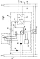
- FIG. 1 to 4 each show one switch arrangement according to the invention.
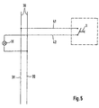
- Figure 5 shows a Switch arrangement according to the prior art.
- 15 denotes a light bulb electrical consumer controlled by a Switch 25, which is preferably designed as a relay, is connected to an electrical power line 30.
- the electrical power line 30 has a phase conductor 31 and a neutral conductor 32.
- the neutral conductor 32 is direct with the light bulb 15 and the phase conductor 31 is over the controlled switch 25 connected to the light bulb 15.
- On Switching contact 1 is connected to a via a first bus coupler 5 Bus line 10 connected.
- the controlled switch 25 is to a second bus coupler 20 Bus line 10 connected. Each bus coupler is through one Address clearly marked.
- the connecting lines between the controlled switch 25 and the second Bus coupler 20, between the switch contact 1 and the first Bus Coupler 5 and between the two Bus Couplers 5 and 20 and bus line 10 are the same as bus line 10 two-wire design.
- a power supply 70 connects the Phase conductor 31 and the neutral conductor 32 of the electrical Power line 30 two-wire with the bus line 10 a voltage of 220 volts on the power line 30 an operating voltage of 5 volts for the bus line 10 transformed and rectified.
- the controlled switch 25, the first bus coupler 5, the second bus coupler 20 and the Switch contact 1 are in a common housing 35 integrated.
- the switch contact 1 is by a mechanical Switch on the housing exterior of the housing 35 from one User operated. To the electrical power line 30 can several electrical consumers, especially in the described way, be connected.
- An actuation of the switching contact 1 is from the first Bus coupler 5 registered and according to the programming of the first bus coupler 5 in the form of a digital Data telegram that contains the address of the corresponding Bus coupler of the switch contact 1 to be switched and switched on the electrical power line 30 connected electrical consumer and the desired switching function contains, from the first bus coupler 5 to the bus line 10 passed.
- the addressing of the electrical to be switched Consumers are therefore addressed via the address assigned to switching electrical consumers Com.
- the second bus coupler 20 the assigned electrical consumers 15 and the first Bus coupler 5 the switch contact 1.
- the Bus technology is a flexible assignment of switch contacts to electrical consumers possible. This assignment is done by programming the Bus switch assigned to the respective switching contact. So can in Figure 1, the first bus coupler 5, for example be programmed so that when the Switching contact 1 the address of the second bus coupler 20 in inserts a corresponding data telegram.
- the first Bus coupler 5 can, however, also be programmed so that at Actuation of the switch contact 1 the address of one other connected to the electrical power line 30 Bus coupler assigned to consumers in a corresponding Data telegram is inserted.
- Figure 5 shows a switch arrangement according to the prior art, in which the light bulb 15 with the neutral conductor 32 of the electrical Power line 30 is connected.
- the phase conductor 31 of the electrical power line 30 is via a first Lead 41, the switch contact 1 and a second Lead 42 can be connected to the light bulb 15.
- first and second feed lines 41 and 42 which are also shown in Figure 1 by the corresponding reference numerals are marked, separated from switch contact 1 and directly can be connected to the controlled switch 25.
- Switch contact 1 is also connected to first bus coupler 5 to join.
- first Bus coupler 5 the second bus coupler 20
- the Switching contact 1 and the controlled switch 25 in one Common housing 35 must be on a wall of a room attached switch contact 1 the room wall only there be torn open where the switch contact 1 is located, to accommodate the housing 35 at this point, and where the supply of the first bus coupler 5 and second bus coupler 20 to the bus line 10, for example as a ring line on or behind one at the base of the Skirting attached to the room wall is routed can.
- bus technology switch arrangement becomes a separation between the power supply and the switch actuation of the user.
- FIG. 2 shows another embodiment of the invention, which differ from the exemplary embodiment according to FIG. 1 differs in that the switch contact 1 is not in Housing 35 is integrated, but via a two-wire Switch contact bus coupler feed line 40 with the first Bus coupler 5 is connected.
- This form of realization allows the housing 35 with the controlled Switches 25, the first and second bus couplers 5 and 20 at a suitable location, for example near a Junction box, in an existing 220V network, represented by the electrical power line 30 to install and with the Bus line 10, which together with the electrical Power line 30 sharing the junction box may be misplaced to connect.
- the microprocessor 45 has Address inputs / outputs 115 for two-wire connection of one Address memory 50 on.
- the microprocessor 45 has also an input 95 for positive operating voltage, via a coil 80 with a positive reference potential having the first wire 11 of the bus line 10 is connected.
- the microprocessor 45 also has an input 100 for the reference potential, which with a that for the Switch arrangement required reference potential second wire 12 of the two-wire bus 10 is connected.
- the positive operating voltage potential of the first wire 11 corresponds to that required for the switch arrangement positive operating voltage potential.
- the one on the bus line 10 transmitted data telegrams are the data signal of the Operating voltage for the switch arrangement superimposed and two-wire via a transformer 90 data inputs / outputs 110 of the microprocessor 45 supplied.
- the microprocessor 45 also has three switch contact inputs 105, which via the switch contact bus coupler feed line 40 with the Switch contact 1 are connected.
- the switch contact bus coupler cable 40 is in this embodiment three-wire, so that for the switch contact 1 in addition to the on / off a third switching function is possible.
- Via a switching output 120 Microprocessor 45 with the base of a npn bipolar transistor 75 connected, the collector of which Input 95 for positive operating voltage and its emitter is connected to the controlled switch 25.
- the controlled switch 25 is in turn connected to input 100 for connected to the reference potential.
- the controlled switch 25 is in a known manner with the light bulb 15 and Power line 30 connected. In a well-known manner are the bus line 10 and the electrical power line 30 connected to each other via the power supply 70.
- the Transmitter 90 serves the data inputs / outputs 110 from the Decouple DC operating voltage on the bus line 10.
- the coil 80 forms a filter element for high-frequency Data signals on bus line 10 from the power supply to decouple the microprocessor 45.
- the control of the controlled switch 25 is carried out by the microprocessor 45 by a corresponding switching signal at switching output 120 of the microprocessor 45, which the bipolar transistor 75 depending on desired switching function opens or closes and as Relay trained controlled switch 25 from isolates or connects positive operating voltage potential, depending on the desired switching state of the relay 25.
- the Microprocessor 45 is now programmed so that one corresponding switching operation of the switching contact 1 a Address is read from the address memory 50 and in Dependence of the switch position of the switch contact 1 desired switching function is recognized. The address and the The desired switching function is then sent to a data telegram is written and the data inputs / outputs 110 Data telegram sent to the bus line 10. On the Bus line 10 then becomes the data telegram to the destination address transfer.
- the exemplary embodiments according to FIG. 1 and FIG. 2 also have Microprocessor 45 a unique address. Data messages, which are transmitted on the bus line 10 and the address of microprocessor 45 are included Microprocessor 45 received via the data inputs / outputs 110 and evaluated. Depending on the one contained in the data telegram desired switching function will be a corresponding one Switching signal at the switching output 120 of the microprocessor 45 emitted the base input of the bipolar transistor 75.
- the bus coupler and controlled switch 25 integrated in the common housing 35, but not the switch contact 1, which is via the Switch contact bus coupler feed line 40 with the one in the housing 35 located circuit is connected.
- the no bus line 10 is required. Rather is the first Bus coupler 5 with a transmission unit 55, the one Transmitting antenna 56 has two wires connected. Entspechend the second bus coupler 20 is two-wire with one Receiving unit 60, which has a receiving antenna 61, connected. There is also a control center 65 which has a transmit / receive antenna 66.
- the Data telegram is thus transmitted via radio and from the Transceiver antenna 66 of the center 65 received.
- the Central 65 serves as a relay station and sends it Data telegram via the transmit / receive antenna 66 to the im Address contained in the data telegram. With appropriate spatial arrangement of the bus coupler can also be used several centers 65 may be necessary.
- One to the second Bus coupler 20 addressed data telegram is received through the receiving antenna 61 of the receiving unit 60 in second bus coupler 20 evaluated.
- the controlled switch 25 then becomes dependent on that in the data telegram contained desired switching function from the second Bus coupler 20 for a corresponding switching process causes.
- the controlled switch 25 the switch contact 1, the first and the second bus coupler 5 and 20 and the transmission unit 55 and the receiving unit 60 in the common housing 35 accommodated.
- the connection of the light bulb 15 to the electrical power line 30 and the controlled Switch 25 is in accordance with the embodiment Figure 1 realized.
- the spatial arrangement of the bus coupler can also be based on the Central 65 can be dispensed with as a relay station and the Data telegrams are sent directly between the corresponding Bus couplers replaced.
Landscapes
- Engineering & Computer Science (AREA)
- Physics & Mathematics (AREA)
- General Physics & Mathematics (AREA)
- Automation & Control Theory (AREA)
- Computer Networks & Wireless Communication (AREA)
- Power Engineering (AREA)
- Remote Monitoring And Control Of Power-Distribution Networks (AREA)
- Keying Circuit Devices (AREA)
Description
Claims (9)
- Schalteranordnung zur An- und Abschaltung der elektrischen Energiezufuhr von elektrischen Verbrauchern, wobei ein elektrischer Verbraucher (15) über einen von einem zweiten BUS-Koppler (20) gesteuerten Schalter (25) mit einer elektrischen Energieleitung (30), an die weitere elektrische Verbraucher anschließbar sind, verbindbar ist, wobei ein Schaltkontakt (1) mit einem ersten BUS-Koppler (5) verbunden ist, dadurch gekennzeichnet, dass bei Betätigung des Schaltkontaktes (1) durch einen Benutzer mittels eines Schalters der erste BUS-Koppler die Adresse eines vom Schaltkontakt (1) zu schaltenden und an die elektrische Energieleitung (30) angeschlossenen elektrischen Verbrauchers und die gewünschte Schaltfunktion in Form eines Datentelegramms aussendet, dass der zweite BUS-Koppler (20) einen Schaltvorgang des gesteuerten Schalters (25) in Abhängigkeit eines an den dem zweiten BUS-Koppler (20) zugeordneten elektrischen Verbraucher (15) adressierten und an den zweiten BUS-Koppler (20) übertragenen Datentelegramms einleitet und dass der erste und der zweite BUS-Koppler (5, 20) in einem gemeinsamen Gehäuse (35) untergebracht sind.
- Schalteranordnung nach Anspruch 1, dadurch gekennzeichnet, daß die Adresse des vom Schaltkontakt (1) zu schaltenden elektrischen Verbrauchers (15) durch entsprechende Programmierung des ersten Buskopplers (5) vorgebbar ist.
- Schalteranordnung nach Anspruch 1 oder 2, dadurch gekennzeichnet, daß der gesteuerte Schalter (25) ein Relais ist.
- Schalteranordnung nach Anspruch 1, 2 oder 3, dadurch gekennzeichnet, daß der Schaltkontakt (1) und/oder der gesteuerte Schalter (25) in dem Gehäuse (35) integriert sind.
- Schalteranordnung nach einem der vorherigen Ansprüche, dadurch gekennzeichnet, daß der erste und der zweite Buskoppler (5, 20) in einem gemeinsamen elektronischen Baustein (45) integriert sind.
- Schalteranordnung nach Anspruch 5, dadurch gekennzeichnet, daß der gemeinsame elektronische Baustein (45) ein Mikroprozessor ist.
- Schalteranordnung nach Anspruch 5 oder 6, dadurch gekennzeichnet, daß an den gemeinsamen elektronischen Baustein (45) ein Adressenspeicher (50) angeschlossen ist.
- Schalteranordnung nach einem der vorherigen Ansprüche, dadurch gekennzeichnet, daß der erste und der zweite Buskoppler (5, 20) an eine Busleitung (10), die zur Übertragung der Datentelegramme dient, angeschlossen sind.
- Schalteranordnung nach einem der Ansprüche 1 bis 7, dadurch gekennzeichnet, daß der erste Buskoppler (5) mit einer Sendeeinheit (55) zum Aussenden von Datentelegrammen verbunden ist, daß der zweite Buskoppler (20) mit einer Empfangseinheit (60) zum Empfang von Datentelegrammen verbunden ist und daß die Übertragung von Datentelegrammen über Funk erfolgt.
Applications Claiming Priority (2)
| Application Number | Priority Date | Filing Date | Title |
|---|---|---|---|
| DE19606579 | 1996-02-22 | ||
| DE19606579A DE19606579A1 (de) | 1996-02-22 | 1996-02-22 | Schalteranordnung zur An- und Abschaltung der elektrischen Energiezufuhr von elektrischen Verbrauchern |
Publications (3)
| Publication Number | Publication Date |
|---|---|
| EP0791871A2 EP0791871A2 (de) | 1997-08-27 |
| EP0791871A3 EP0791871A3 (de) | 1998-04-22 |
| EP0791871B1 true EP0791871B1 (de) | 2002-10-09 |
Family
ID=7786095
Family Applications (1)
| Application Number | Title | Priority Date | Filing Date |
|---|---|---|---|
| EP96118510A Expired - Lifetime EP0791871B1 (de) | 1996-02-22 | 1996-11-19 | Schalteranordnung zur An- und Abschaltung der elektrischen Energiezufuhr von elektrischen Verbrauchern |
Country Status (3)
| Country | Link |
|---|---|
| EP (1) | EP0791871B1 (de) |
| AT (1) | ATE225951T1 (de) |
| DE (2) | DE19606579A1 (de) |
Families Citing this family (7)
| Publication number | Priority date | Publication date | Assignee | Title |
|---|---|---|---|---|
| DE29807271U1 (de) * | 1998-04-17 | 1998-06-18 | Siemens AG, 80333 München | Schaltersteuerung mit einer seriellen Schnittstelle |
| DE10013303A1 (de) * | 2000-03-17 | 2001-09-20 | Abb Patent Gmbh | Ein-/Ausgabegerät zur Verwendung in einem Gebäudeinstallationssystem |
| DE10035813A1 (de) * | 2000-07-22 | 2002-01-31 | Abb Patent Gmbh | Installationsgerät für den Anschluß an Busleitungen eines Hausleitsystems, insbesondere des EIB-Bussystems |
| GB0220050D0 (en) * | 2002-08-29 | 2002-10-09 | Xpeqt Ag | Addressable relay assembly |
| BE1016386A3 (fr) * | 2004-12-17 | 2006-10-03 | Mantec | Centrale domotique. |
| EP2299340A1 (de) * | 2009-09-17 | 2011-03-23 | Patrick Barbedor | Zentrale, System und Verfahren zur Steuerung von Funktionseinrichtungen in Gebäuden |
| DE102018108973B4 (de) * | 2018-04-16 | 2021-09-09 | Technisat Digital Gmbh | Vorrichtung zum Betreiben in einer Heimautomation eingerichtet zum Schalten einer Schaltleitung |
Citations (1)
| Publication number | Priority date | Publication date | Assignee | Title |
|---|---|---|---|---|
| DE4425876A1 (de) * | 1994-07-09 | 1996-01-11 | Wolfgang Dipl Jur Reimann | Intelligente Steckdose |
Family Cites Families (6)
| Publication number | Priority date | Publication date | Assignee | Title |
|---|---|---|---|---|
| DE3608910A1 (de) * | 1986-03-17 | 1987-09-24 | Siemens Ag | Kombinierte elektrische anschlusseinheit fuer leistungs- und informationsanschluss |
| DE3843944A1 (de) * | 1988-12-24 | 1990-06-28 | Asea Brown Boveri | In einem gehaeuse angeordnetes elektrisches schuetz |
| EP0513443B1 (de) * | 1991-05-06 | 1999-11-17 | Koninklijke Philips Electronics N.V. | Gebäudeleitsystem |
| US5821876A (en) * | 1991-10-08 | 1998-10-13 | Square D Company | Communication interface for bus connected circuit breakers |
| DE4311096C2 (de) * | 1993-04-03 | 1996-06-20 | Abb Patent Gmbh | Teilnehmereinrichtung für ein Installationsbussystem |
| DE9311707U1 (de) * | 1993-08-05 | 1994-12-01 | Siemens AG, 80333 München | Koppeladapter zum Anschließen eines Schutzschalters an einem Bus |
-
1996
- 1996-02-22 DE DE19606579A patent/DE19606579A1/de not_active Ceased
- 1996-11-19 DE DE59609780T patent/DE59609780D1/de not_active Expired - Lifetime
- 1996-11-19 AT AT96118510T patent/ATE225951T1/de not_active IP Right Cessation
- 1996-11-19 EP EP96118510A patent/EP0791871B1/de not_active Expired - Lifetime
Patent Citations (1)
| Publication number | Priority date | Publication date | Assignee | Title |
|---|---|---|---|---|
| DE4425876A1 (de) * | 1994-07-09 | 1996-01-11 | Wolfgang Dipl Jur Reimann | Intelligente Steckdose |
Also Published As
| Publication number | Publication date |
|---|---|
| ATE225951T1 (de) | 2002-10-15 |
| DE59609780D1 (de) | 2002-11-14 |
| EP0791871A2 (de) | 1997-08-27 |
| EP0791871A3 (de) | 1998-04-22 |
| DE19606579A1 (de) | 1997-08-28 |
Similar Documents
| Publication | Publication Date | Title |
|---|---|---|
| EP0344609B1 (de) | Digitales Signalübertragungssystem für die Hausleittechnik | |
| EP0772132B1 (de) | Aktor/Sensor-Kombination für die Gebäudesystemtechnik | |
| EP0790541B1 (de) | Anschlusseinrichtung für ein elektrisches Installationssystem | |
| DE10127821C5 (de) | Anordnung zum Betrieb eines Elektro-Schraubers | |
| EP0346614B1 (de) | Verfahren zum Initialisieren eines digitalen Signalübertragungssystems | |
| EP0791871B1 (de) | Schalteranordnung zur An- und Abschaltung der elektrischen Energiezufuhr von elektrischen Verbrauchern | |
| DE19544027C2 (de) | Bussystem, insbesondere zur elektrischen Installation | |
| EP0402654B1 (de) | Anschlussvorrichtung für den Anschluss elektrischer Verbraucher | |
| EP1734636B1 (de) | Schaltdose | |
| DE102017115735A1 (de) | Steuer-Schaltmodul für eine Gebäudesteuerungseinrichtung und eine solche Gebäudesteuerungseinrichtung | |
| EP0437696B1 (de) | Fernschalt- oder fernsteuerbare Anschlussvorrichtung | |
| EP3799534B1 (de) | Funktionsmodul | |
| DE19640300A1 (de) | Installationssystem | |
| DE19610381C2 (de) | Installationsbussystem für eine Stromschienenbeleuchtung | |
| EP2502354B1 (de) | Elektrisches installationssystem | |
| DE19645626B4 (de) | Busgerät für den Anschluss an ein Bussystem der Gebäudesystemtechnik | |
| EP1289217B1 (de) | Kommunikation mittels Wechselstromhalbwellen | |
| WO2006074640A2 (de) | Stromanschlussklemme | |
| AT500806B1 (de) | Bausatz von leiterplatten für den anschluss von elektrischen geräten, insbesondere dimmern, transformatoren und vorschaltgeräten | |
| DE19927869C1 (de) | Elektroinstallationseinrichtung für Gebäude | |
| DE102015121173A1 (de) | Bedienungseinrichtung, Bedienungssystem und Modul zum mechanischen und funktechnischen Initialisieren einer Funktionalität zum Einbau für Unterputzdosen | |
| DE19620820B4 (de) | Elektrisches Anschlußsystem zur Übertragung digitaler Signale zwischer einer Telematik-Anlage und peripheren Elektronikeinheiten | |
| DE29724594U1 (de) | Anschlusseinrichtung für ein elektrisches Installationssystem | |
| DE10004098A1 (de) | Elektrische Kombinationssteckverbindung | |
| DE19915458C1 (de) | Vorrichtung zum Netzfreischalten einer elektrischen Versorgungsleitung |
Legal Events
| Date | Code | Title | Description |
|---|---|---|---|
| PUAI | Public reference made under article 153(3) epc to a published international application that has entered the european phase |
Free format text: ORIGINAL CODE: 0009012 |
|
| AK | Designated contracting states |
Kind code of ref document: A2 Designated state(s): AT CH DE FR GB IT LI |
|
| PUAL | Search report despatched |
Free format text: ORIGINAL CODE: 0009013 |
|
| AK | Designated contracting states |
Kind code of ref document: A3 Designated state(s): AT CH DE FR GB IT LI |
|
| 17P | Request for examination filed |
Effective date: 19981022 |
|
| 17Q | First examination report despatched |
Effective date: 19991201 |
|
| GRAG | Despatch of communication of intention to grant |
Free format text: ORIGINAL CODE: EPIDOS AGRA |
|
| GRAG | Despatch of communication of intention to grant |
Free format text: ORIGINAL CODE: EPIDOS AGRA |
|
| GRAH | Despatch of communication of intention to grant a patent |
Free format text: ORIGINAL CODE: EPIDOS IGRA |
|
| GRAH | Despatch of communication of intention to grant a patent |
Free format text: ORIGINAL CODE: EPIDOS IGRA |
|
| GRAA | (expected) grant |
Free format text: ORIGINAL CODE: 0009210 |
|
| AK | Designated contracting states |
Kind code of ref document: B1 Designated state(s): AT CH DE FR GB IT LI |
|
| REF | Corresponds to: |
Ref document number: 225951 Country of ref document: AT Date of ref document: 20021015 Kind code of ref document: T |
|
| REG | Reference to a national code |
Ref country code: GB Ref legal event code: FG4D Free format text: NOT ENGLISH |
|
| REG | Reference to a national code |
Ref country code: CH Ref legal event code: NV Representative=s name: SCINTILLA AG, DIREKTION Ref country code: CH Ref legal event code: EP |
|
| REF | Corresponds to: |
Ref document number: 59609780 Country of ref document: DE Date of ref document: 20021114 |
|
| GBT | Gb: translation of ep patent filed (gb section 77(6)(a)/1977) |
Effective date: 20030203 |
|
| ET | Fr: translation filed | ||
| PLBE | No opposition filed within time limit |
Free format text: ORIGINAL CODE: 0009261 |
|
| STAA | Information on the status of an ep patent application or granted ep patent |
Free format text: STATUS: NO OPPOSITION FILED WITHIN TIME LIMIT |
|
| 26N | No opposition filed |
Effective date: 20030710 |
|
| PGFP | Annual fee paid to national office [announced via postgrant information from national office to epo] |
Ref country code: CH Payment date: 20081124 Year of fee payment: 13 |
|
| PGFP | Annual fee paid to national office [announced via postgrant information from national office to epo] |
Ref country code: AT Payment date: 20081120 Year of fee payment: 13 |
|
| PGFP | Annual fee paid to national office [announced via postgrant information from national office to epo] |
Ref country code: IT Payment date: 20081126 Year of fee payment: 13 |
|
| PGFP | Annual fee paid to national office [announced via postgrant information from national office to epo] |
Ref country code: GB Payment date: 20091123 Year of fee payment: 14 Ref country code: FR Payment date: 20091202 Year of fee payment: 14 |
|
| PGFP | Annual fee paid to national office [announced via postgrant information from national office to epo] |
Ref country code: DE Payment date: 20100121 Year of fee payment: 14 |
|
| REG | Reference to a national code |
Ref country code: CH Ref legal event code: PL |
|
| PG25 | Lapsed in a contracting state [announced via postgrant information from national office to epo] |
Ref country code: AT Free format text: LAPSE BECAUSE OF NON-PAYMENT OF DUE FEES Effective date: 20091119 |
|
| PG25 | Lapsed in a contracting state [announced via postgrant information from national office to epo] |
Ref country code: LI Free format text: LAPSE BECAUSE OF NON-PAYMENT OF DUE FEES Effective date: 20091130 Ref country code: CH Free format text: LAPSE BECAUSE OF NON-PAYMENT OF DUE FEES Effective date: 20091130 |
|
| PG25 | Lapsed in a contracting state [announced via postgrant information from national office to epo] |
Ref country code: IT Free format text: LAPSE BECAUSE OF NON-PAYMENT OF DUE FEES Effective date: 20091119 |
|
| GBPC | Gb: european patent ceased through non-payment of renewal fee |
Effective date: 20101119 |
|
| REG | Reference to a national code |
Ref country code: FR Ref legal event code: ST Effective date: 20110801 |
|
| REG | Reference to a national code |
Ref country code: DE Ref legal event code: R119 Ref document number: 59609780 Country of ref document: DE Effective date: 20110601 Ref country code: DE Ref legal event code: R119 Ref document number: 59609780 Country of ref document: DE Effective date: 20110531 |
|
| PG25 | Lapsed in a contracting state [announced via postgrant information from national office to epo] |
Ref country code: DE Free format text: LAPSE BECAUSE OF NON-PAYMENT OF DUE FEES Effective date: 20110531 |
|
| PG25 | Lapsed in a contracting state [announced via postgrant information from national office to epo] |
Ref country code: FR Free format text: LAPSE BECAUSE OF NON-PAYMENT OF DUE FEES Effective date: 20101130 |
|
| PG25 | Lapsed in a contracting state [announced via postgrant information from national office to epo] |
Ref country code: GB Free format text: LAPSE BECAUSE OF NON-PAYMENT OF DUE FEES Effective date: 20101119 |