EP2502354B1 - Elektrisches installationssystem - Google Patents
Elektrisches installationssystem Download PDFInfo
- Publication number
- EP2502354B1 EP2502354B1 EP10798965.9A EP10798965A EP2502354B1 EP 2502354 B1 EP2502354 B1 EP 2502354B1 EP 10798965 A EP10798965 A EP 10798965A EP 2502354 B1 EP2502354 B1 EP 2502354B1
- Authority
- EP
- European Patent Office
- Prior art keywords
- installation
- accordance
- installation unit
- electrical
- telegram
- Prior art date
- Legal status (The legal status is an assumption and is not a legal conclusion. Google has not performed a legal analysis and makes no representation as to the accuracy of the status listed.)
- Active
Links
Images


Classifications
-
- H—ELECTRICITY
- H04—ELECTRIC COMMUNICATION TECHNIQUE
- H04B—TRANSMISSION
- H04B3/00—Line transmission systems
- H04B3/54—Systems for transmission via power distribution lines
-
- H—ELECTRICITY
- H04—ELECTRIC COMMUNICATION TECHNIQUE
- H04L—TRANSMISSION OF DIGITAL INFORMATION, e.g. TELEGRAPHIC COMMUNICATION
- H04L12/00—Data switching networks
- H04L12/02—Details
- H04L12/10—Current supply arrangements
-
- H—ELECTRICITY
- H04—ELECTRIC COMMUNICATION TECHNIQUE
- H04L—TRANSMISSION OF DIGITAL INFORMATION, e.g. TELEGRAPHIC COMMUNICATION
- H04L12/00—Data switching networks
- H04L12/28—Data switching networks characterised by path configuration, e.g. LAN [Local Area Networks] or WAN [Wide Area Networks]
- H04L12/2803—Home automation networks
-
- H—ELECTRICITY
- H04—ELECTRIC COMMUNICATION TECHNIQUE
- H04L—TRANSMISSION OF DIGITAL INFORMATION, e.g. TELEGRAPHIC COMMUNICATION
- H04L12/00—Data switching networks
- H04L12/28—Data switching networks characterised by path configuration, e.g. LAN [Local Area Networks] or WAN [Wide Area Networks]
- H04L12/40—Bus networks
- H04L12/40006—Architecture of a communication node
- H04L12/40045—Details regarding the feeding of energy to the node from the bus
-
- H—ELECTRICITY
- H05—ELECTRIC TECHNIQUES NOT OTHERWISE PROVIDED FOR
- H05B—ELECTRIC HEATING; ELECTRIC LIGHT SOURCES NOT OTHERWISE PROVIDED FOR; CIRCUIT ARRANGEMENTS FOR ELECTRIC LIGHT SOURCES, IN GENERAL
- H05B47/00—Circuit arrangements for operating light sources in general, i.e. where the type of light source is not relevant
- H05B47/10—Controlling the light source
- H05B47/105—Controlling the light source in response to determined parameters
-
- H—ELECTRICITY
- H01—ELECTRIC ELEMENTS
- H01H—ELECTRIC SWITCHES; RELAYS; SELECTORS; EMERGENCY PROTECTIVE DEVICES
- H01H2300/00—Orthogonal indexing scheme relating to electric switches, relays, selectors or emergency protective devices covered by H01H
- H01H2300/03—Application domotique, e.g. for house automation, bus connected switches, sensors, loads or intelligent wiring
-
- H—ELECTRICITY
- H04—ELECTRIC COMMUNICATION TECHNIQUE
- H04B—TRANSMISSION
- H04B2203/00—Indexing scheme relating to line transmission systems
- H04B2203/54—Aspects of powerline communications not already covered by H04B3/54 and its subgroups
- H04B2203/5429—Applications for powerline communications
- H04B2203/5458—Monitor sensor; Alarm systems
-
- Y—GENERAL TAGGING OF NEW TECHNOLOGICAL DEVELOPMENTS; GENERAL TAGGING OF CROSS-SECTIONAL TECHNOLOGIES SPANNING OVER SEVERAL SECTIONS OF THE IPC; TECHNICAL SUBJECTS COVERED BY FORMER USPC CROSS-REFERENCE ART COLLECTIONS [XRACs] AND DIGESTS
- Y02—TECHNOLOGIES OR APPLICATIONS FOR MITIGATION OR ADAPTATION AGAINST CLIMATE CHANGE
- Y02B—CLIMATE CHANGE MITIGATION TECHNOLOGIES RELATED TO BUILDINGS, e.g. HOUSING, HOUSE APPLIANCES OR RELATED END-USER APPLICATIONS
- Y02B90/00—Enabling technologies or technologies with a potential or indirect contribution to GHG emissions mitigation
- Y02B90/20—Smart grids as enabling technology in buildings sector
-
- Y—GENERAL TAGGING OF NEW TECHNOLOGICAL DEVELOPMENTS; GENERAL TAGGING OF CROSS-SECTIONAL TECHNOLOGIES SPANNING OVER SEVERAL SECTIONS OF THE IPC; TECHNICAL SUBJECTS COVERED BY FORMER USPC CROSS-REFERENCE ART COLLECTIONS [XRACs] AND DIGESTS
- Y04—INFORMATION OR COMMUNICATION TECHNOLOGIES HAVING AN IMPACT ON OTHER TECHNOLOGY AREAS
- Y04S—SYSTEMS INTEGRATING TECHNOLOGIES RELATED TO POWER NETWORK OPERATION, COMMUNICATION OR INFORMATION TECHNOLOGIES FOR IMPROVING THE ELECTRICAL POWER GENERATION, TRANSMISSION, DISTRIBUTION, MANAGEMENT OR USAGE, i.e. SMART GRIDS
- Y04S20/00—Management or operation of end-user stationary applications or the last stages of power distribution; Controlling, monitoring or operating thereof
- Y04S20/14—Protecting elements, switches, relays or circuit breakers
Definitions
- the invention relates to an electrical installation system according to the preamble of patent claim 1 (see. DE 299 14 873 U1 ).
- installation devices are arranged in electrical supply lines of loads, via which the loads can be controlled manually or automatically directly and according to a wide variety of criteria.
- bus systems are known in which installation devices in the form of sensors and actuators communicate by means of telegrams via bus lines and control loads arranged in a separate load circuit. Such bus systems are expensive and can be installed in the context of modernization only with considerable effort.
- EP 0 854 668 A2 discloses a bus system with devices for installation in an installation box, wherein the devices send data telegrams for switching a lighting on a data bus and wherein the power supply and the data transmission takes place via a single wire pair.
- EP 1 489 718 A2 discloses an electrical installation system for controlling an electrical building installation with a programmable arithmetic unit, which control signals are supplied to the circuit of electrical consumers via control lines, wherein the installation system is powered by the electrical power grid to which the consumers are connected.
- Electrical loads can be controlled over different lengths operations on the respective installation equipment.
- a distinction between switching and, for example, dimming is achieved by short and long operating times. Long press will dim, while a short press will turn on or off the load.
- a correspondingly prolonged switching pulse in the form of an analogue voltage level is transmitted from the extension to the load-switching insert of a main station.
- the signal length as a decision parameter can be critical, because depending on the time of the meeting of the actuating signal and an evaluation routine of a control electronics of the main body not always an identical action is generated at the load.
- This can be disadvantageous, in particular, in the case of the central control of several main stations, since the evaluation routines in the individual main locations do not run in a synchronized manner and the same switching action may not be executed for all connected loads. For example, individual loads may be intentionally turned off, while at other loads, contrary to the intent, a dimming process occurs.
- the object of the present invention is to provide an electrical installation system that allows extended functionality in private branch operation and generates reliable switching actions.
- the invention according to claim 1 has the advantage that an existing installation system in which installation devices and loads are arranged in a circuit and a control of the loads of spaced installation equipment takes place, with little effort by using existing piping systems and simple replacement of installation equipment functional can be extended.
- the installation devices can be equipped with multiple switching functions. From extensions central different states can be controlled at load switching main points. In PBX operation, ambiguous switching pulses can be avoided. The result is a comfortable and reliable system that can be used as part of a modernization as well as the first installation.
- An existing, preferably 2-core, line system between installation devices at branches and at main offices can be used further.
- a supplement, z. B. by separate or additional bus lines, is not necessary.
- the one core can be used for mutual power supply, while the other wire can serve as a telegram line that connects the keypads with each other.
- a first installation device for a load-switching main point may comprise a switching module and a pre-set application module with electronic assemblies and front-mounted controls.
- a second installation device for an extension can have an assembly for power supply and a module for telegram generation and front-mounted controls.
- the power supply of the second installation device via the line system to the first installation device and the connected load.
- the configuration of the components of the second installation device can be chosen so that the amount of energy available in this way adequately ensures the necessary functions. With the amount of energy telegrams can be generated and internal components can be supplied.
- the energy is buffered in the second installation device in an internal, preferably capacitive, assembly.
- the power supply of the second installation device can be continuous, advantageously also during a telegram transmission. A separate or different power supply is not necessary.
- the second installation device triggers an operating action within the module for telegram generation, preferably using a microprocessor, a generation of digital signals via the existing (then shorted to phase) wire as a message to the application module of the first installation device (main office) be transmitted.
- the telegram is sent unidirectionally in the direction of the receiving main office. To avoid collisions with other telegrams on the same line, all system components work according to the "listen before talk" principle.
- the information content of the telegram allows a clear evaluation in the first installation device (main office), so that the connected load can be controlled in the intended manner.
- the telegram may include information about the length of the actuation of a control element and / or information which operating element of the second installation device is actuated. There are no values, eg. B. dimming levels transmitted.
- time criterion in the second installation device is converted into a digital telegram.
- a defined over the length of the voltage signal switching action is interpreted as a long or short operation with non-uniform load action depending on unsynchronized evaluation structures.
- the telegram contains information for identifying the operating element of a second installation device.
- second installation devices can have a plurality of operating elements, so that convenient switching actions are possible.
- additional control elements for activating user-defined load settings can be created. From branches can thus be operated independently of each other several main offices.
- the setting of the user-defined load states for a so-called scene takes place by means of local setting of a load state and assignment to the corresponding control element of a first installation device (main point).
- the assigned load state in the first installation device is then called up on the basis of the transmitted message information.
- the arrangement and control of the controls should be consistent on the installation equipment involved to avoid malfunction.
- predefined functions can therefore be assigned to the operating elements.
- the invention can be used in the integration of additional functionalities in installation systems.
- central controls and signal transmitters timing, motion detectors, radio components
- time, wind or light-controlled elements can be integrated into the system.
- the devices can be combined into lines, groups and other systems.
- the devices can also be equipped with 3-wire technology, d. H. with direct 2-wire connection to the supply network and a telegram.
- wired components and wireless components can be used, for example, for data transmission by means of radio or infrared signals.
- a wirelessly communicating functional module can be integrated into an installation device. The necessary power supply can be supplied via the device base, while the signal transmission can be wireless.
- Advantageous areas of application of the installation system according to the invention can result in the field of lighting or blind control.
- FIGS. 1 and 2 schematically two circuit arrangements are sketched, which represent the prior art.
- FIG. 1 shows a conventional changeover circuit, in which a load 1 via two remote control points in the form of mechanical switches 2 can be switched on or off.
- the switches 2 interrupt or close a directly leading to the load 1 line system 3.
- the switches 2 are interconnected via two mutually used wires 4 and 5.
- the load 1 is considered exemplary in the description as a light source. However, other types of load can also be used, for example blinds or other motor-driven consumers.
- FIG. 2 a more comfortable solution is shown, wherein instead of the two mechanical switches on the one hand a button 6 and on the other hand an installation device 7 are used with dimming function.
- the brightness of the load 1 connected to the installation device 7 can be set directly on the installation device 7, a so-called main point.
- the button 6 represents an extension and acts as a parallel connected control point on the installation device 7 in order to adjust the brightness of the load 1 can.
- Main and extension are connected via a line system 3, wherein the wire 4 ensures the power supply of the installation device 7, while the wire 5 acts as a jumper wire and is connected to a so-called extension port 8 of the installation device 7.
- an analogue signal corresponding to the actuation period is transmitted via the wire 5 to the installation device 7.
- the signal length serves as a criterion for switching on or off or increasing or decreasing the load 1, it only being possible to control from the respective load state to the opposite load state.
- the installation system according to the invention is suitable for example in the FIG. 1 and in the FIG. 2 Functionally extended to illustrate conventional installation systems or to make safer in their application.
- the installation devices are replaced at the respective control stations.
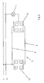
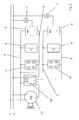
- the load of the load 1 associated with the control point (main office) with a first installation device 9 and the other spatially spaced control point (extension) is equipped with a second installation device 10.
- the existing line system 3 can be used further, with the wire 4 providing the connection from an external power supply to the first installation device 9 and to the second installation device 10, while the wire 5 connects the installation devices 9 and 10 with each other.
- the installation system may comprise further first installation devices 9 and second installation devices 10, which are connected in parallel with each other.
- the installation system can also be realized as part of an initial installation.
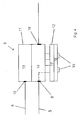
- the first installation device (main station) 9 is constructed in two parts and consists of a switching module 11 and an application module 12 (FIG. FIG. 4 ).
- the switching module 11 comprises a power supply 13 and type-specific electrical components 14 which, depending on the type, can be designed as a switching relay, shutter control or dimmer insert.
- the wire 4 of the line system 3 is connected to a terminal 15 of the switching module 11 to the power supply 13, while the wire 5 of the line system 3 and the load 1 at terminals 8 and 16 of the switching module 11 are contacted. Via the connection 8, a connection to the second installation device 10 is created, wherein the input-side connection is routed internally to the application module 12 with the switching module 11.
- the application module 12 is mechanically and electrically detachably connected to the switching module 11.
- the application module 12 includes the functional control electronics 17 (dimmer, blinds) and the sensor 18 for operating the first installation device 9, for example, control elements 19 or wireless interfaces (not shown), which can be operated by radio or infrared signals.
- the second installation device (extension) 10 is constructed in one piece and includes a module 20 for power supply and a module 21 for telegram generation, the respective system intelligence, z.
- a module 20 for power supply and a module 21 for telegram generation, the respective system intelligence, z.
- Front side is a sensor 22 for operating the second installation device 10, for example, controls 23, respectively.
- a separate power supply and additional wireless interfaces are possible, which can be operated by radio or infrared signals.
- the wires 4 and 5 of the conduit system 3 are contacted at terminals 24 and 25 and connected internally to the assemblies 20 and 21.
- the path runs from the external power supply, via the wire 4, the assembly 20 for power supply in the second installation device 10, the wire. 5 , through the first installation device 9 and via the load 1 back to the external power supply.
- the energy is buffered in the second installation device 10 in the internal, preferably capacitive, assembly 20.
- the power supply of the module 20 is continuous, advantageously also during telegram transmission. The design and scope of the telegram are selected so that the required amount of energy is in the range of a few milliwatts and at any time despite the connected load 1 can be tapped. A separate source is not necessary, so that the existing line system 3 can continue to be used.
- controls 19 and 23 are the same and preferably predefined on the participating installation devices 9 and 10, so that this results in a uniform operating methodology.
- the controls 19 and 23 are associated with fixed functionalities such.
- the second installation device 10 trigger operating actions within the assembly 21, preferably using a microprocessor, a generation of digital signals, the wire 4 and the wire 5 are shorted according to the signal.
- the signals are combined in the form of a telegram and transmitted via this line connection to the application module 12 of the first installation device 9. There, the telegram is converted into a defined switching action on a load 1.
- the telegram contains information about the used control element 23 and the operating time.
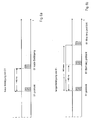
- the distinguishing criterion for a short or long operating time can be z. B. 450 ms. An actuation longer than 5 sec will automatically lead to a timeout.
- FIG. 6a and in FIG. 6b are typical telegrams for a short operation and a long operation of a control element 23 is shown, a short operation, for example, causes a switching on of the load, while a long operation causes a "start-up" of the load. On another control element 23, for example, switching off and "shutdown" of the load can be done.
- the respective control element 23, here S1 identified and stored as information in the telegram.
- the further information added to the telegram via a short press ( FIG. 6a ).
- the respective control element 23 is also first identified and stored as information in the telegram and, for an actuation time longer than 450 ms, the information is also added to the telegram via a long actuation.
- the information about the end of the operation ( FIG. 6b ).
- the telegram is transmitted unidirectionally to the first installation device 9, so that the system components are principally divided into transmitters (second installation devices, buttons, multi-switch, central unit, wind sensor ...) and receivers (first installation devices, switching modules).
- transmitters second installation devices, buttons, multi-switch, central unit, wind sensor ...)
- receivers first installation devices, switching modules.
- the telegram is digital and includes, for example, 2 bytes consisting of the information (control element, operating time) and their repetition. Typically, such a telegram takes 64 ms. The energy required is in the range of a few microamps (50-200 microamps per unit).
- first installation devices 9 and also all second installation devices 10 each four operating elements (S1-S4), wherein in the Figures 7-9 a highly schematic representation of the first installation device 9 has been selected.
- the operating elements S1 and S3 are defined for switching on and off or for dimming and dimming a load 1, wherein a short actuation of S1 causes the switching on and a long operation causes the load 1 to dim. A brief press of S3 will turn off and a long press will turn off the load 1.
- the controls S2 and S4 are defined as scene buttons.
- the setting of individual dimming states of parallel loads 1 ( figure 7 ) for a scene takes place in each case by means of local setting of a dimming value at the respective installation device 9.
- one of the operating elements S2 or S4 is actuated locally and the operating action (operating element, operating time) is assigned to the dimming value.
- the respective assigned load states in the first installation devices 9 are then retrieved on the basis of the transmitted telegram information. For example, this results in the possibility to set several installation devices 9 on actuation of the scene button S2 to 30%, 50% and 80% power.
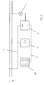
- the installation devices 9, 10 can be combined into lines, groups and other systems, in particular dimming functionalities and blinds controls are conceivable. Furthermore, the invention can be used in the integration of additional functionalities in installation systems. For example, additional central controls 26 and signal transmitter 27 (timers, motion detectors, radio components) as well as time, wind or light-controlled elements can be integrated into the system ( FIG. 9 ). Each installation device 10 is connected to an extension terminal 8 of the associated first installation device 9. Optionally, the installation devices 10 also with 3-wire technology be equipped, ie with 2-wire connection to the supply network and a telegram.
Landscapes
- Engineering & Computer Science (AREA)
- Computer Networks & Wireless Communication (AREA)
- Signal Processing (AREA)
- Power Engineering (AREA)
- Automation & Control Theory (AREA)
- Selective Calling Equipment (AREA)
- Circuit Arrangement For Electric Light Sources In General (AREA)
- Remote Monitoring And Control Of Power-Distribution Networks (AREA)
- Arrangements For Transmission Of Measured Signals (AREA)
- Power-Operated Mechanisms For Wings (AREA)
- Keying Circuit Devices (AREA)
Description
- Die Erfindung betrifft ein elektrisches Installationssystem nach dem Oberbegriff des Patentanspruchs 1 (vgl.
DE 299 14 873 U1 ). - Im Rahmen der Gebäudeinstallationstechnik existieren verschiedene elektrische Installationssysteme, um die Energieversorgung von elektrischen Lasten zu steuern. Bei einem weit verbreiteten Installationssystem werden in elektrischen Versorgungsleitungen von Lasten Installationsgeräte angeordnet, über die die Lasten direkt und nach unterschiedlichsten Kriterien manuell oder automatisch ansteuerbar sind.
- Des weiteren sind Bussysteme bekannt, bei denen Installationsgeräte in Form von Sensoren und Aktoren mittels Telegrammen über Busleitungen kommunizieren und in einem separaten Lastkreis angeordnete Lasten ansteuern. Derartige Bussysteme sind kostenintensiv und lassen sich im Rahmen einer Modernisierung nur mit erheblichem Aufwand installieren.
- Darüber hinaus gibt es ein Mischsystem der vorgenannten Systeme, bei dem über vorhandene Versorgungsleitungen zusätzlich Telegramme zur Ansteuerung von Sensoren und Aktoren gesendet werden. Die Kombinierung von Telegrammen und Lastsignalen auf dem selben Leitungsnetz bedingt jedoch eine erhebliche Störanfälligkeit eines solchen Systems.
- "The One-Single-Standard for the integration of Home and Building applications", KNX System Architecture, Konnex Association, 1. April 2003, offenbart ein elektrisches Installationssystem für Gebäude, bei dem mehrere Geräte über ein Energieversorgungsnetzwerk miteinander kommunizieren. Ein ähnliches System ist in Kyselytsya Y et. al. "Implementation of the KNX Standard", 1. Oktober 2006, beschrieben.
-
EP 0 854 668 A2 offenbart ein Bussystem mit Geräten zum Einbau in eine Installationsdose, wobei die Geräte Datentelegramme zum Schalten einer Beleuchtung auf einen Datenbus senden und wobei die Spannungsversorgung und die Datenübertragung über ein einziges Adernpaar erfolgen. -
EP 1 489 718 A2 offenbart ein elektrisches Installationssystem zur Steuerung einer elektrischen Gebäudeinstallation mit einer programmierbaren Recheneinheit, welcher zur Schaltung elektrischer Verbraucher über Steuerleitungen Steuersignale zuführbar sind, wobei das Installationssystem über das elektrische Energieversorgungsnetz mit Energie versorgt wird, an dem die Verbraucher angeschlossen sind. - Aus der
US 2008/258650 A1 ist ein Laststeuersystem bekannt, bei dem eine Hauptstelle und mehrere Nebenstellen mit einer Last in Serie geschaltet sind. - Aus der
US 5 248 919 A ist eine Lichtsteuereinrichtung bekannt, bei der verschiedene Intensitätsstufen vom Benutzer ausgewählt werden können. - Konventionelle Installationssysteme sind in der Funktionsvielfalt gegenüber Bussystemen jedoch deutlich im Nachteil. Bei der Steuerung von Lasten von mehreren Schaltstellen sind herkömmliche Mehrwege- oder Nebenstellenverdrahtungen hinsichtlich der Schaltfunktionen und deren Ausführung sowohl bei der Erstinstallation als bei einer Modernisierung verbesserungsfähig. Die bekannten Funktionen von Nebenstellen ermöglichen nur eine einheitliche Lastveränderung. Eine zentrale Ansteuerung mehrerer Lasten mit unterschiedlichen Lastzuständen ist nicht möglich.
- Elektrische Lasten können dabei über unterschiedlich lange Betätigungen an den jeweiligen Installationsgeräten gesteuert werden. Eine Unterscheidung zwischen Schalten und beispielsweise Dimmen wird durch kurze und lange Betätigungszeiten erreicht. Bei langer Betätigung wird gedimmt, während eine kurze Betätigung ein Ein- bzw. Ausschalten der Last bewirkt. Während der Betätigungszeit wird ein entsprechend andauernder Schaltimpuls in Form eines analogen Spannungspegels von der Nebenstelle an den Last schaltenden Einsatz einer Hauptstelle übertragen.
- Die Signallänge als Entscheidungsparameter kann kritisch sein, da abhängig vom Zeitpunkt des Aufeinandertreffens des Betätigungssignals und einer Auswertungsroutine einer Steuerungselektronik der Hauptstelle nicht immer eine identische Aktion an der Last generiert wird. Dies kann insbesondere bei der zentralen Ansteuerung mehrerer Hauptstellen nachteilig sein, da die Auswertungsroutinen in den einzelnen Hauptstellen nicht synchronisiert ablaufen und möglicherweise nicht bei allen angeschlossenen Lasten die gleiche Schaltaktion ausgeführt wird. Beispielsweise können einzelne Lasten beabsichtigungsgemäß ausgeschaltet werden, während bei anderen Lasten entgegen der Absicht ein Dimmprozess erfolgt.
- Die Aufgabe der vorliegenden Erfindung besteht darin, ein elektrisches Installationssystem zu schaffen, das erweiterte Funktionalitäten im Nebenstellenbetrieb ermöglicht und zuverlässige Schaltaktionen generiert.
- Gelöst wird diese Aufgabe durch die im Patentanspruch 1 angegebenen Merkmale. Vorteilhafte Ausgestaltungen ergeben sich aus der Beschreibung, den Zeichnungen und den Unteransprüchen.
- Die Erfindung gemäß dem Patentanspruch 1 weist den Vorteil auf, dass ein bestehendes Installationssystem bei denen Installationsgeräte und Lasten in einem Stromkreis angeordnet sind und eine Ansteuerung der Lasten von beabstandet angeordneten Installationsgeräten erfolgt, mit geringem Aufwand durch Nutzung vorhandener Leitungssysteme und durch einfachen Austausch von Installationsgeräten funktional erweitert werden können. Die Installationsgeräte können mit multiplen Schaltfunktionen ausgestattet werden. Von Nebenstellen können zentral unterschiedliche Zustände an Last schaltenden Hauptstellen gesteuert werden. Im Nebenstellenbetrieb können mehrdeutige Schaltimpulse vermieden werden. Es entsteht ein komfortables und zuverlässiges System, das sowohl im Rahmen einer Modernisierung als auch als bei der Erstinstallation verwendet werden kann.
- Ein bestehendes, vorzugsweise 2-adriges, Leitungssystem zwischen Installationsgeräten an Nebenstellen und an Hauptstellen kann weiter genutzt werden. Eine Ergänzung, z. B. durch separate oder zusätzliche Busleitungen, ist nicht notwendig. In der bestehenden Verdrahtung zwischen den Bedienstellen kann die eine Ader zur beiderseitigen Spannungsversorgung genutzt werden, während die weitere Ader als Telegrammleitung dienen kann, die die Bedienstellen untereinander verbindet.
- Vorhandene Installationsgeräte an den jeweiligen Bedienstellen müssen ausgetauscht werden, wobei der prinzipielle Geräteaufbau erhalten bleiben kann. Ein erstes Installationsgerät für eine Last schaltende Hauptstelle kann ein Schaltmodul und ein vorgesetztes Applikationsmodul mit Elektronikbaugruppen und frontseitig angeordneten Bedienelementen umfassen. Ein zweites Installationsgerät für eine Nebenstelle kann eine Baugruppe zur Energieversorgung und eine Baugruppe zur Telegrammerzeugung sowie frontseitig angeordneten Bedienelementen aufweisen.
- Die Energieversorgung des zweiten Installationsgerätes erfolgt über das Leitungssystem zum ersten Installationsgerät und die daran angeschlossene Last. Die Konfiguration der Bauteile des zweiten Installationsgerätes kann so gewählt werden, dass die auf diesem Wege zur Verfügung stehende Energiemenge die notwendigen Funktionen hinreichend gewährleistet. Mit der Energiemenge können Telegramme erzeugt werden und interne Bauelemente versorgt werden. Die Energie wird in dem zweiten Installationsgerät in einer internen, vorzugsweise kapazitiv wirkenden, Baugruppe gepuffert. Die Energieversorgung des zweiten Installationsgerätes kann stetig, vorteilhafterweise auch während einer Telegrammübertragung, erfolgen. Eine separate oder andere Spannungsversorgung ist nicht notwendig.
- In dem zweiten Installationsgerät (Nebenstelle) löst eine Bedienaktion innerhalb der Baugruppe zur Telegrammerzeugung, vorzugsweise unter Nutzung eines Mikroprozessors, eine Generierung digitaler Signale aus, die über die vorhandene (dann gegen Phase kurzgeschlossene) Ader als Telegramm an das Applikationsmodul des ersten Installationsgerätes (Hauptstelle) übertragen werden. Das Telegramm wird unidirektional in Richtung der empfangenden Hauptstelle verschickt. Um Kollisionen mit anderen Telegrammen auf derselben Leitung zu vermeiden, arbeiten alle Systemkomponenten nach dem Prinzip "listen before talk". Der Informationsgehalt des Telegramms ermöglicht eine eindeutige Auswertung in dem ersten Installationsgerät (Hauptstelle), so dass die angeschlossene Last in beabsichtigter Weise angesteuert werden kann.
- Das Telegramm kann eine Information über die Länge der Betätigung eines Bedienelementes und/oder eine Information, welches Bedienelement des zweiten Installationsgerätes betätigt wird, beinhalten. Es werden keine Werte, z. B. Dimmstärken, übertragen.
- Wesentlich ist dabei, dass das Zeitkriterium in dem zweiten Installationsgerät in ein digitales Telegramm umgewandelt wird. Somit ist ausgeschlossen, dass ein über die Länge des Spannungssignals definierte Schaltaktion abhängig von unsynchronisierten Auswertestrukturen als lange oder kurze Betätigung mit uneinheitlicher Lastaktion interpretiert wird.
- Erfindungsgemäß enthält das Telegramm Informationen zur Identifizierung des Bedienelementes eines zweiten Installationsgerätes. Durch diese Unterscheidung können zweite Installationsgeräte mehrere Bedienelemente aufweisen, so dass komfortable Schaltaktionen möglich sind. Neben Bedienelementen für das Auf- und Abdimmen können so auch zusätzlich Bedienelemente für die Aktivierung von nutzerdefinierten Lasteinstellungen geschaffen werden. Von Nebenstellen können somit mehrere Hauptstellen unabhängig voneinander betätigt werden.
- Die Einstellung der nutzerdefinierten Lastzustände für eine sogenannte Szene erfolgt mittels lokaler Einstellung eines Lastzustandes und Zuordnung zum entsprechenden Bedienelement eines ersten Installationsgerätes (Hauptstelle). Bei einer Betätigung des entsprechenden Bedienelementes an einem zweiten Installationsgerät (Nebenstelle) wird dann auf Grund der übermittelten Telegramminformation der zugeordnete Lastzustand in dem ersten Installationsgerät abgerufen. Die Anordnung und Ansteuerung der Bedienelemente sollte an den beteiligten Installationsgeräten einheitlich sein, um Fehlfunktionen zu vermeiden. Vorzugsweise können den Bedienelementen deshalb vordefinierte Funktionen zugewiesen werden.
- Weiterhin ist eine Kombination mit mechanischen Tastern als Nebenstelle möglich, da die Installationsmethodik beibehalten wird. Der mechanische Taster dominiert immer die elektronischen Nebenstellen, da dieser Taster im betätigten Zustand immer einen Kurzschluss der Telegrammleitung gegen Phase darstellt.
- Des weiteren kann die Erfindung bei der Integration von weiteren Funktionalitäten in Installationssysteme Verwendung finden. Beispielsweise lassen sich zusätzlich Zentralsteuerungen und Signalgeber (Schaltuhren, Bewegungsmelder, Funkkomponenten) sowie Zeit, Wind oder Licht gesteuerte Elemente in das System integrieren. Die Geräte können zu Linien, Gruppen und weiteren Systemen zusammenfasst werden. Optional können die Geräte auch mit 3-Leiter-Technik ausgestattet sein, d. h. mit direkter 2-adriger Anbindung an das Versorgungsnetz und einer Telegrammader.
- Neben drahtgebundenen Bauelementen können auch drahtlos wirkende Bauelemente verwendet werden, beispielsweise zur Datenübertragung mittels Funk- oder Infrarotsignalen. Vorteilhafterweise kann ein drahtlos kommunizierendes Funktionsmodul in ein Installationsgerät integriert werden. Die notwendige Spannungsversorgung kann über den Gerätesockel geliefert werden, während die Signalübertragung drahtlos erfolgen kann.
- Vorteilhafte Anwendungsbereiche des erfindungsgemäßen Installationssystems können sich im Bereich der Beleuchtungs- oder der Jalousiesteuerung ergeben.
- Weitere Einzelheiten, Merkmale und Vorteile der Erfindung ergeben sich aus nachfolgender Beschreibung eines bevorzugten Ausführungsbeispieles anhand der Zeichnungen.
- Es zeigen:
- Fig. 1
- schematisch eine bekannte Wechselschaltung,
- Fig. 2
- schematisch eine bekannte Nebenstellenschaltung,
- Fig. 3
- schematisch eine erfindungsgemäße Nebenstellenschaltung,
- Fig. 4
- schematisch einen Aufbau eines ersten Installationsgerätes (Hauptstelle),
- Fig. 5
- schematisch einen Aufbau eines zweiten Installationsgerätes (Nebenstelle),
- Fig. 6a
- ein Telegramm einer kurzen Betätigung eines zweiten Installationsgerätes,
- Fig. 6b
- ein Telegramm einer langen Betätigung eines zweiten Installationsgerätes,
- Fig. 7
- schematisch eine erweiterte Schaltungsanordnung mit mehreren zweiten Installationsgeräten,
- Fig. 8
- schematisch eine erweiterte Schaltungsanordnung mit einem mechanischen Taster und
- Fig. 9
- schematisch eine erweiterte Schaltungsanordnung mit gruppierten Installationsgeräten.
- Gleiche oder gleichwirkende Bauteile sind in der nachfolgenden Beschreibung mit gleichen Bezugszeichen versehen.
- In den
Figuren 1 und2 sind schematisch zwei Schaltungsanordnungen skizziert, die den Stand der Technik darstellen. - In
Figur 1 ist eine herkömmliche Wechselschaltung dargestellt, bei der eine Last 1 über zwei entfernt voneinander angeordnete Bedienstellen in Form von mechanischen Schaltern 2 ein- bzw. ausgeschaltet werden kann. Die Schalter 2 unterbrechen oder schließen dabei ein direkt zur Last 1 führendes Leitungssystem 3. Die Schalter 2 sind untereinander über zwei wechselseitig genutzte Adern 4 und 5 verbunden. Die Last 1 wird in der Beschreibung beispielshaft als Leuchtmittel betrachtet. Es sind jedoch auch andere Lasttypen einsetzbar, zum Beispiel Jalousien oder andere motorisch gesteuerte Verbraucher. - In
Figur 2 ist eine etwas komfortablere Lösung dargestellt, wobei anstelle der beiden mechanischen Schalter einerseits ein Taster 6 und andererseits ein Installationsgerät 7 mit Dimmfunktion benutzt werden. Die Helligkeit der an das Installationsgerät 7 angeschlossenen Last 1 kann am Installationsgerät 7, einer sogenannten Hauptstelle, direkt eingestellt werden. Der Taster 6 stellt eine Nebenstelle dar und wirkt als parallel geschaltete Bedienstelle auf das Installationsgerät 7 ein, um die Helligkeit der Last 1 einstellen zu können. Haupt- und Nebenstelle sind über ein Leitungssystem 3 verbunden, wobei die Ader 4 die Spannungsversorgung des Installationsgerätes 7 gewährleistet, während die Ader 5 als Schaltdraht fungiert und an einen sogenannten Nebenstellenanschluss 8 des Installationsgerätes 7 angeschlossen ist. Bei einer Betätigung des Tasters 6 wird ein der Betätigungsdauer entsprechendes analoges Signal über die Ader 5 an das Installationsgerät 7 übertragen. Die Signallänge dient dabei als Kriterium für ein Ein- oder Ausschalten bzw. Auf- oder Abdimmen der Last 1, wobei nur vom jeweiligen Lastzustand ausgehend in den entgegengesetzten Lastzustand gesteuert werden kann. - Nachfolgend werden der Aufbau und die Funktionsweise des erfindungsgemäßen elektrischen Installationssystems schematisch anhand von Ausführungsbeispielen näher beschrieben.
- Das erfindungsgemäße Installationssystem eignet sich beispielsweise um die in der
Figur 1 und in derFigur 2 dargestellten herkömmlichen Installatiönssysteme funktional zu erweitern bzw. sicherer in ihrer Anwendung zu machen. Hierzu werden die Installationsgeräte an den jeweiligen Bedienstellen ausgetauscht. Dabei wird die der Last 1 schaltungstechnisch zugeordnete Bedienstelle (Hauptstelle) mit einem ersten Installationsgerät 9 und die andere, räumlich beabstandete Bedienstelle (Nebenstelle) mit einem zweiten Installationsgerät 10 ausgestattet. Das vorhandene Leitungssystem 3 kann weiter genutzt werden, wobei die Ader 4 die Verbindung von einer externen Spannungsversorgung zu dem ersten Installationsgerät 9 und zu dem zweiten Installationsgeräten 10 schafft, während die Ader 5 die Installationsgeräte 9 und 10 untereinander verbindet. Neben der in derFigur 3 dargestellten Konfiguration kann das Installationssystem weitere erste Installationsgeräte 9 und zweite Installationsgeräte 10 aufweisen, die parallel zueinander verschaltet werden. Das Installationssystem kann auch im Rahmen einer Erstinstallation realisiert werden. - Das erste Installationsgerät (Hauptstelle) 9 ist zweiteilig aufgebaut und besteht aus einem Schaltmodul 11 und einem Applikationsmodul 12 (
Figur 4 ). Das Schaltmodul 11 umfasst eine Spannungsversorgung 13 und typspezifische elektrische Bauteile 14, die je nach Typ als Schaltrelais, Jalousiesteuerung oder Dimmereinsatz ausgebildet sein können. Die Ader 4 des Leitungssystems 3 ist an einem Anschluss 15 des Schaltmoduls 11 mit der Spannungsversorgung 13 verbunden, während die Ader 5 des Leitungssystems 3 und die Last 1 an Anschlüssen 8 und 16 des Schaltmoduls 11 kontaktiert sind. Über den Anschluss 8 wird eine Verbindung zum zweiten Installationsgerät 10 geschaffen, wobei die eingangsseitige Verbindung mit dem Schaltmodul 11 intern an das Applikationsmodul 12 weitergeleitet wird. Das Applikationsmodul 12 ist mechanisch und elektrisch mit dem Schaltmodul 11 lösbar verbunden. Das Applikationsmodul 12 beinhaltet die funktionsgemäße Steuerelektronik 17 (Dimmer, Jalousie) sowie die Sensorik 18 zur Bedienung des ersten Installationsgerätes 9, beispielsweise Bedienelemente 19 oder drahtlose Schnittstellen (nicht dargestellt), die per Funk- oder Infrarotsignale bedienbar sind. - Das zweite Installationsgerät (Nebenstelle) 10 ist einteilig aufgebaut und beinhaltet eine Baugruppe 20 zur Energieversorgung und eine Baugruppe 21 zur Telegrammerzeugung, die die jeweilige Systemintelligenz, z. B. in Form eines Mikroprozessors, beinhaltet (
Figur 5 ). Frontseitig ist eine Sensorik 22 zur Bedienung des zweiten Installationsgerätes 10, beispielsweise Bedienelemente 23, angeordnet. In einer weiteren, nicht dargestellten Ausführung mit einem separaten Netzteil sind auch zusätzliche drahtlose Schnittstellen möglich, die per Funk- oder Infrarotsignale bedienbar sind. Die Adern 4 und 5 des Leitungssystems 3 sind an Anschlüssen 24 und 25 kontaktiert und intern mit den Baugruppen 20 und 21 verbunden. - Eine notwendige Energieversorgung des zweiten Installationsgerätes 10 erfolgt über das Leitungssystem 3 zum ersten Installationsgerät 9 und die angeschlossene Last 1. Der Pfad verläuft dabei von der externen Energieversorgung, über die Ader 4, die Baugruppe 20 zur Energieversorgung in dem zweiten Installationsgerät 10, die Ader 5, durch das erste Installationsgerät 9 und über die Last 1 zurück zur externen Energieversorgung. Die Energie wird in dem zweiten Installationsgerät 10 in der internen, vorzugsweise kapazitiv wirkenden, Baugruppe 20 gepuffert. Die Energieversorgung der Baugruppe 20 erfolgt stetig, vorteilhafterweise auch während der Telegrammübertragung. Die Gestaltung und der Umfang des Telegramms sind so gewählt, dass die benötigte Energiemenge im Bereich von wenigen Milliwatt liegt und jederzeit trotz der angeschlossenen Last 1 abgegriffen werden kann. Eine separate Quelle ist nicht notwendig, so dass das vorhandene Leitungssystem 3 weiterhin genutzt werden kann.
- Die Anordnung und Ansteuerung von Bedienelementen 19 und 23 ist an den beteiligten Installationsgeräten 9 und 10 gleich und vorzugsweise vordefiniert, so dass sich hierdurch eine einheitliche Bedienmethodik ergibt. Den Bedienelementen 19 und 23 sind feste Funktionalitäten zugeordnet, wie z. B. An, Aus, Auf- oder Abdimmen, Szene, die durch unterschiedlich lange Betätigungen weiter differenziert sind.
- In dem zweiten Installationsgerät 10 lösen Bedienaktionen innerhalb der Baugruppe 21, vorzugsweise unter Nutzung eines Mikroprozessors, eine Generierung digitaler Signale aus, wobei die Ader 4 und die Ader 5 signalgemäß kurzgeschlossen werden. Die Signale werden in Form eines Telegramms zusammengefasst und über diese Leitungsverbindung an das Applikationsmodul 12 des ersten Installationsgerätes 9 übertragen. Dort wird das Telegramm in eine definierte Schaltaktion an einer Last 1 umgesetzt.
- Das Telegramm beinhaltet Informationen über das genutzte Bedienelement 23 und die Bediendauer. Das Unterscheidungskriterium für eine kurze oder lange Bediendauer kann z. B. 450 ms betragen. Eine Betätigung länger als 5 sec führt automatisch zu einem Timeout. In
Figur 6a und inFigur 6b sind typische Telegramme für eine kurze Betätigung und eine lange Betätigung eines Bedienelementes 23 dargestellt, wobei eine kurze Betätigung beispielsweise ein Einschalten der Last bewirkt, während eine lange Betätigung ein "Hochfahren" der Last bewirkt. An einem anderen Bedienelement 23 kann beispielsweise ein Ausschalten und "Runterfahren" der Last erfolgen. Zuerst wird das jeweilige Bedienelement 23, hier S1, identifiziert und als Information in das Telegramm hinterlegt. Bei einer Betätigungszeit unterhalb von 450 ms wird des weiteren die Information über eine kurze Betätigung dem Telegramm hinzugefügt (Figur 6a ). Bei einer langen Betätigungszeit wird ebenfalls zuerst das jeweilige Bedienelement 23 identifiziert und als Information in das Telegramm hinterlegt und bei einer Betätigungszeit länger als 450 ms des weiteren die Information über eine lange Betätigung dem Telegramm hinzugefügt. Abschließend folgt die Information über das Ende der Betätigung (Figur 6b ). - Das Telegramm wird unidirektional an das erste Installationsgerät 9 übermittelt, so dass die Systemkomponenten prinzipiell in Transmitter (zweite Installationsgeräte, Taster, Multi-Switch, Zentraleinheit, Windsensor ...) und in Receiver (erste Installationsgeräte, Schaltmodule) unterteilt sind. Um Kollisionen mit anderen Telegrammen auf derselben Leitung zu vermeiden, arbeiten alle Nebenstellen einheitlich nach dem Prinzip "listen before talk". Das Telegramm ist digital und umfasst beispielsweise 2 Bytes bestehend aus der Information (Bedienelement, Bediendauer) und deren Wiederholung. Typischerweise dauert ein solches Telegramm 64ms. Die benötigte Energie liegt im Bereich weniger Mikroampere (50 - 200 Mikroampere per Unit).
- Beispielhaft weisen in den
Figuren 3 ,7-9 alle ersten Installationsgeräte 9 und auch alle zweiten Installationsgeräte 10 jeweils vier Bedienelemente (S1-S4), wobei in denFiguren 7-9 eine stark schematisierte Darstellung des ersten Installationsgerätes 9 gewählt worden ist. Die Bedienelemente S1 und S3 sind dabei zum An- und Ausschalten bzw. Auf und Abdimmen einer Last 1 definiert, wobei eine kurze Betätigung von S1 das Einschalten und eine lange Betätigung das Aufdimmen der Last 1 bewirkt. Eine kurze Betätigung von S3 bewirkt das Ausschalten und eine lange Betätigung das Abdimmen der Last 1. - Die Bedienelemente S2 und S4 sind als Szenetaster definiert. Die Einstellung individueller Dimmzustände von parallel geschalteten Lasten 1 (
Figur 7 ) für eine Szene erfolgt jeweils mittels lokaler Einstellung eines Dimmwertes an dem jeweiligen Installationsgerät 9. Anschließend wird lokal eines der Bedienelemente S2 oder S4 betätigt und die Bedienaktion (Bedienelement, Bediendauer) dem Dimmwert zugeordnet. Bei einer Betätigung des entsprechenden Bedienelementes S2 oder S4 an einem zweiten Installationsgerät 10 werden dann auf Grund der übermittelten Telegramminformation die jeweilig zugeordneten Lastzustände in den ersten Installätionsgeräten 9 abgerufen. Beispielsweise ergibt sich hierdurch die Möglichkeit mehrere Installationsgeräte 9 bei Betätigung des Szenetasters S2 auf 30 %, 50 % und 80 % Leistung einzustellen. - Weiterhin ist eine Kombination mit einem mechanischen Taster 6 als Nebenstelle möglich, da die grundsätzliche Installationsmethode beibehalten wird (
Figur 8 ). Der mechanische Taster 6 dominiert immer die elektronischen Nebenstellen 10, da dieser Taster 6 im betätigten Zustand immer einen Kurzschluss der Ader 5 gegen Phase darstellt. Eine kurze Betätigung führt dabei ausgehend vom Zustand der Last 1 in den gegensätzlichen Zustand (von An zu Aus bzw. von Aus zu An). Eine lange Betätigung zum gegensätzlichen Auf- oder Abdimmen. - Die Installationsgeräte 9, 10 lassen sich zu Linien, Gruppen und weiteren Systemen zusammenfassen, wobei insbesondere Dimmfunktionalitäten und Jalousiesteuerungen denkbar sind. Des weiteren kann die Erfindung bei der Integration von weiteren Funktionalitäten in Installationssysteme Verwendung finden. Beispielsweise lassen sich zusätzliche Zentralsteuerungen 26 und Signalgeber 27 (Schaltuhren, Bewegungsmelder, Funkkomponenten) sowie Zeit, Wind oder Licht gesteuerte Elemente in das System integrieren (
Figur 9 ). Jedes Installationsgerät 10 ist mit einem Nebenstellenanschluss 8 des zugeordneten ersten Installationsgerätes 9 verbunden. Optional können die Installationsgeräte 10 auch mit 3-Leiter-Technik ausgestattet sein, d. h. mit 2-adriger Anbindung an das Versorgungsnetz und einer Telegrammader. -
- 1
- Last
- 2
- Schalter
- 3
- Leitungssystem
- 4
- Ader
- 5
- Ader
- 6
- mechanischer Taster
- 7
- Installationsgerät mit Dimmfunktion
- 8
- Anschluss (Nebenstelle)
- 9
- erstes Installationsgerät (Hauptstelle)
- 10
- zweites Installationsgerät (Nebenstelle)
- 11
- Schaltmodul
- 12
- Applikationsmodul
- 13
- Spannungsversorgung
- 14
- typspezifische Bauteile
- 15
- Anschluss (Versorgung)
- 16
- Anschluss (Last)
- 17
- Steuerelektronik
- 18
- Sensorik
- 19
- Bedienelemente
- 20
- Baugruppe (Spannungsversorgung)
- 21
- Baugruppe (Telegramm)
- 22
- Sensorik
- 23
- Bedienelemente S1 - S4
- 24
- Anschluss (Versorgung)
- 25
- Anschluss (Telegramm)
- 26
- Zentralsteuerung
- 27
- Signalgeber
Claims (12)
- Elektrisches Installationssystem umfassend mindestens ein erstes Installationsgerät (9), das eine angeschlossene Last (1) schaltet, mindestens ein zweites Installationsgerät (10) mit einer Bediensensorik (22) und mindestens ein zweiadriges Leitungssystem (3), durch das die beiden Installationsgeräte (9, 10) elektrisch verbunden sind, wobei eine Ader (4) des Leitungssystems (3) mit einer externen Energieversorgung verbunden ist und eine Ader (5) die Installationsgeräte (9, 10) untereinander verbindet, dadurch gekennzeichnet,
dass das zweite Installationsgerät (10) mehrere Bedienelemente (23) aufweist,
dass das zweite Installationsgerät (10) eine Baugruppe (20) zur internen Energieversorgung aufweist, die über das Leitungssystem (3) zum ersten Installationsgerät (9) und über die angeschlossene Last (1) mit Energie versorgt wird,
dass das zweite Installationsgerät (10) eine Baugruppe (21) zur Telegrammerzeugung aufweist, und
dass durch eine Betätigung der Bediensensorik (22) des zweiten Installationsgerätes (10) in der Baugruppe (21) digitale Signale generiert und in Form eines Telegrammes zusammengefasst werden, das Informationen über das genutzte Bedienelement (23) und über die Bediendauer der Bediensensorik (22) beinhaltet, und das über die Ader (5), die die Installationsgeräte (9, 10) miteinander verbindet, an das erste Installationsgerät (9) übertragen wird und das in dem ersten Installationsgerät (9) eine Schaltaktion für die angeschlossene Last (1) generiert. - Elektrisches Installationssystem nach einem der vorhergehenden Patentansprüche, dadurch gekennzeichnet, dass die Energieversorgung innerhalb des zweiten Installationsgerätes (10) über ein kapazitives Bauteil erfolgt.
- Elektrisches Installationssystem nach einem der vorhergehenden Patentansprüche, dadurch gekennzeichnet, dass das die Energieversorgung des zweiten Installationsgerätes (10) während der Telegrammübermittlung erfolgt.
- Elektrisches Installationssystem nach einem der vorhergehenden Patentansprüche, dadurch gekennzeichnet, dass das Telegramm in einem Mikroprozessor des zweiten Installationsgerätes (10) erzeugt wird.
- Elektrisches Installationssystem nach einem der vorhergehenden Patentansprüche, dadurch gekennzeichnet, dass die Bediendauer in kurze und lange Betätigungen unterschieden wird.
- Elektrisches Installationssystem nach einem der vorhergehenden Patentansprüche, dadurch gekennzeichnet, dass das erste Installationsgerät (9) ein Schaltmodul (11) und ein Applikationsmodul (12) mit einer Bediensensorik (18) umfasst.
- Elektrisches Installationssystem nach einem der vorhergehenden Patentansprüche, dadurch gekennzeichnet, dass das zweite Installationsgerät (10) elektrisch mit dem Schaltmodul (11) des ersten Installationsgerätes (9) und funktional mit dem Applikationsmodul (12) des ersten Installationsgerätes (9) verbunden ist.
- Elektrisches Installationssystem nach einem der vorhergehenden Patentansprüche, dadurch gekennzeichnet, dass ein zweites Installationsgerät (10) zentral unterschiedliche Lastzustände an mehreren ersten Installationsgeräten (9) ansteuern kann.
- Elektrisches Installationssystem nach einem der vorhergehenden Patentansprüche, dadurch gekennzeichnet, dass erste elektrische Installationsgeräte (9) als Schalt-, Dimm- oder Jalousieeinsätze ausgebildet sind.
- Elektrisches Installationssystem nach einem der vorhergehenden Patentansprüche, dadurch gekennzeichnet, dass zweite Installationsgeräte (10) als Taster, Mehrfachtaster, Zentralsteuerung (26) oder Signalgeber (27) ausgebildet sind.
- Elektrisches Installationssystem nach einem der vorhergehenden Patentansprüche, dadurch gekennzeichnet, dass die Signalgeber (27) als Schaltuhr, Bewegungsmelder, Funkkomponente, Windsensor oder Lichtsensor ausgebildet sind.
- Elektrisches Installationssystem nach einem der vorhergehenden Patentansprüche, dadurch gekennzeichnet, dass erste Installationsgeräte (9) zu Linien, Gruppen und weiteren Systemen zusammengefasst werden.
Applications Claiming Priority (2)
| Application Number | Priority Date | Filing Date | Title |
|---|---|---|---|
| DE102009060273A DE102009060273A1 (de) | 2009-12-23 | 2009-12-23 | Elektrisches Installationssystem |
| PCT/EP2010/007835 WO2011076387A2 (de) | 2009-12-23 | 2010-12-21 | Elektrisches installationssystem |
Publications (2)
| Publication Number | Publication Date |
|---|---|
| EP2502354A2 EP2502354A2 (de) | 2012-09-26 |
| EP2502354B1 true EP2502354B1 (de) | 2016-09-14 |
Family
ID=43827299
Family Applications (1)
| Application Number | Title | Priority Date | Filing Date |
|---|---|---|---|
| EP10798965.9A Active EP2502354B1 (de) | 2009-12-23 | 2010-12-21 | Elektrisches installationssystem |
Country Status (6)
| Country | Link |
|---|---|
| EP (1) | EP2502354B1 (de) |
| CN (1) | CN102783044B (de) |
| BR (1) | BR112012015146B1 (de) |
| DE (1) | DE102009060273A1 (de) |
| RU (1) | RU2560124C2 (de) |
| WO (1) | WO2011076387A2 (de) |
Cited By (1)
| Publication number | Priority date | Publication date | Assignee | Title |
|---|---|---|---|---|
| RU2724643C1 (ru) * | 2019-07-31 | 2020-06-25 | Бейджин Сяоми Мобайл Софтвеа Ко., Лтд. | Переключающее устройство |
Families Citing this family (3)
| Publication number | Priority date | Publication date | Assignee | Title |
|---|---|---|---|---|
| DE102010050748A1 (de) * | 2010-11-08 | 2012-05-10 | Schneider Electric Industries Sas | Elektrisches Installationsgerät |
| EP2632233B1 (de) * | 2012-02-22 | 2017-07-26 | Helvar Oy Ab | Vorrichtung zum Steuern des Betriebs eines elektronischen Ballasts |
| DE102022111620A1 (de) * | 2022-05-10 | 2023-11-16 | Schneider Electric Industries Sas | Schaltsteuerungsvorrichtung, schaltvorrichtung, schaltsystem, leistungsschaltsteuerungsverfahren und leistungsschaltverfahren |
Citations (3)
| Publication number | Priority date | Publication date | Assignee | Title |
|---|---|---|---|---|
| US5248919A (en) * | 1992-03-31 | 1993-09-28 | Lutron Electronics Co., Inc. | Lighting control device |
| DE29914873U1 (de) * | 1999-08-26 | 1999-12-30 | Insta Elektro GmbH & Co KG, 58511 Lüdenscheid | Helligkeitssteuerung von Beleuchtungseinrichtungen über Haupt- und Nebenstellen |
| US20080258650A1 (en) * | 2007-04-23 | 2008-10-23 | Lutron Electronics Co., Inc. | Multiple Location Load Control System |
Family Cites Families (5)
| Publication number | Priority date | Publication date | Assignee | Title |
|---|---|---|---|---|
| AT405998B (de) * | 1997-01-21 | 2000-01-25 | Felten & Guilleaume Ag Oester | Eib-gerät zum einbau in eine installationsdose |
| HUP0104960A2 (hu) * | 2001-11-15 | 2003-07-28 | Attila Murlasits | Berendezés és eljárás elektromos fogyasztók működésének szabályzására |
| RU2249925C2 (ru) * | 2003-03-27 | 2005-04-10 | Общество с ограниченной ответственностью "Электронгарантсервис" | Устройство управления освещением |
| DE10327504B4 (de) * | 2003-06-17 | 2007-05-03 | Theben Ag | Multifunktionsgerät |
| CN2643417Y (zh) * | 2003-08-08 | 2004-09-22 | 陈孝坚 | 改进的电气开关装置 |
-
2009
- 2009-12-23 DE DE102009060273A patent/DE102009060273A1/de not_active Withdrawn
-
2010
- 2010-12-21 RU RU2012131151/07A patent/RU2560124C2/ru active
- 2010-12-21 BR BR112012015146-0A patent/BR112012015146B1/pt active IP Right Grant
- 2010-12-21 WO PCT/EP2010/007835 patent/WO2011076387A2/de not_active Ceased
- 2010-12-21 CN CN201080064608.0A patent/CN102783044B/zh active Active
- 2010-12-21 EP EP10798965.9A patent/EP2502354B1/de active Active
Patent Citations (3)
| Publication number | Priority date | Publication date | Assignee | Title |
|---|---|---|---|---|
| US5248919A (en) * | 1992-03-31 | 1993-09-28 | Lutron Electronics Co., Inc. | Lighting control device |
| DE29914873U1 (de) * | 1999-08-26 | 1999-12-30 | Insta Elektro GmbH & Co KG, 58511 Lüdenscheid | Helligkeitssteuerung von Beleuchtungseinrichtungen über Haupt- und Nebenstellen |
| US20080258650A1 (en) * | 2007-04-23 | 2008-10-23 | Lutron Electronics Co., Inc. | Multiple Location Load Control System |
Cited By (2)
| Publication number | Priority date | Publication date | Assignee | Title |
|---|---|---|---|---|
| RU2724643C1 (ru) * | 2019-07-31 | 2020-06-25 | Бейджин Сяоми Мобайл Софтвеа Ко., Лтд. | Переключающее устройство |
| US11581157B2 (en) | 2019-07-31 | 2023-02-14 | Beijing Xiaomi Mobile Software Co., Ltd. | Smart switch device with manual control and intelligent control functions |
Also Published As
| Publication number | Publication date |
|---|---|
| RU2012131151A (ru) | 2014-01-27 |
| CN102783044B (zh) | 2016-03-16 |
| CN102783044A (zh) | 2012-11-14 |
| RU2560124C2 (ru) | 2015-08-20 |
| WO2011076387A3 (de) | 2011-09-22 |
| WO2011076387A2 (de) | 2011-06-30 |
| EP2502354A2 (de) | 2012-09-26 |
| DE102009060273A1 (de) | 2011-06-30 |
| BR112012015146B1 (pt) | 2021-06-01 |
| BR112012015146A2 (pt) | 2016-07-12 |
Similar Documents
| Publication | Publication Date | Title |
|---|---|---|
| EP1064759B1 (de) | Verfahren zum inbetriebnehmen eines bussystems sowie entsprechendes bussystem | |
| EP0790541B1 (de) | Anschlusseinrichtung für ein elektrisches Installationssystem | |
| DE19544027C2 (de) | Bussystem, insbesondere zur elektrischen Installation | |
| DE102014019725C5 (de) | Elektronische Schaltvorrichtung und elektronisches Schaltverfahren | |
| EP2502354B1 (de) | Elektrisches installationssystem | |
| EP2048916B1 (de) | Intelligentes Leuchtensystem | |
| EP3799534B1 (de) | Funktionsmodul | |
| DE202010007203U1 (de) | Elektroverteilung für die Versorgung von Lampengruppen | |
| DE102017115735B4 (de) | Steuer-Schaltmodul für eine Gebäudesteuerungseinrichtung und eine solche Gebäudesteuerungseinrichtung | |
| EP2517329B1 (de) | Fernsteuerbarer schalter | |
| DE19610381C2 (de) | Installationsbussystem für eine Stromschienenbeleuchtung | |
| DE19645626B4 (de) | Busgerät für den Anschluss an ein Bussystem der Gebäudesystemtechnik | |
| EP2395627B1 (de) | Installationsgerät sowie Einsatzgerät und Aufsatzgerät für ein Installationsgerät | |
| EP1993010B1 (de) | Sensoreinheit | |
| DE19619175B4 (de) | Anordnung zur Erzeugung von Lichtszenen | |
| DE102006062751A1 (de) | Multidimmer, welcher universell als Masterdimmer, als Slavedimmer oder als Nebenstelle einsetzbar ist | |
| EP3627658B1 (de) | Verfahren zum betreiben eines elektrischen verbrauchermoduls sowie elektrisches verbrauchersystem | |
| WO2008040390A1 (de) | Beleuchtungssystem und verfahren zum betreiben eines beleuchtungssystems | |
| EP3657272A1 (de) | Bediengerät für die hausautomatisierung | |
| DE102011015605A1 (de) | Heimnetzwerk zur Ansteuerung von Geräten | |
| EP2736193B1 (de) | Elektrisches/elektronisches Installationsgerät | |
| WO2006074640A2 (de) | Stromanschlussklemme | |
| DE102009059269B3 (de) | Busteilnehmer, Busankoppler sowie Verfahren zum Bereitstellen und Nutzen einer Schnittstelle | |
| EP2614599B1 (de) | Elektrisches installationsgerät | |
| EP3664304A1 (de) | Ein- und auskoppelung von daten und datentransport über elektrische versorgungsleitung von beleuchtungssystemen |
Legal Events
| Date | Code | Title | Description |
|---|---|---|---|
| PUAI | Public reference made under article 153(3) epc to a published international application that has entered the european phase |
Free format text: ORIGINAL CODE: 0009012 |
|
| 17P | Request for examination filed |
Effective date: 20120619 |
|
| AK | Designated contracting states |
Kind code of ref document: A2 Designated state(s): AL AT BE BG CH CY CZ DE DK EE ES FI FR GB GR HR HU IE IS IT LI LT LU LV MC MK MT NL NO PL PT RO RS SE SI SK SM TR |
|
| DAX | Request for extension of the european patent (deleted) | ||
| 17Q | First examination report despatched |
Effective date: 20150728 |
|
| GRAP | Despatch of communication of intention to grant a patent |
Free format text: ORIGINAL CODE: EPIDOSNIGR1 |
|
| RIC1 | Information provided on ipc code assigned before grant |
Ipc: H04B 3/54 20060101AFI20160309BHEP Ipc: H02J 13/00 20060101ALI20160309BHEP Ipc: H04L 12/10 20060101ALI20160309BHEP Ipc: H04L 12/40 20060101ALI20160309BHEP Ipc: H04L 12/28 20060101ALI20160309BHEP Ipc: H05B 37/02 20060101ALI20160309BHEP |
|
| INTG | Intention to grant announced |
Effective date: 20160324 |
|
| GRAS | Grant fee paid |
Free format text: ORIGINAL CODE: EPIDOSNIGR3 |
|
| GRAA | (expected) grant |
Free format text: ORIGINAL CODE: 0009210 |
|
| AK | Designated contracting states |
Kind code of ref document: B1 Designated state(s): AL AT BE BG CH CY CZ DE DK EE ES FI FR GB GR HR HU IE IS IT LI LT LU LV MC MK MT NL NO PL PT RO RS SE SI SK SM TR |
|
| REG | Reference to a national code |
Ref country code: GB Ref legal event code: FG4D Free format text: NOT ENGLISH |
|
| REG | Reference to a national code |
Ref country code: CH Ref legal event code: EP |
|
| REG | Reference to a national code |
Ref country code: IE Ref legal event code: FG4D Free format text: LANGUAGE OF EP DOCUMENT: GERMAN |
|
| REG | Reference to a national code |
Ref country code: AT Ref legal event code: REF Ref document number: 829999 Country of ref document: AT Kind code of ref document: T Effective date: 20161015 |
|
| REG | Reference to a national code |
Ref country code: DE Ref legal event code: R096 Ref document number: 502010012423 Country of ref document: DE |
|
| REG | Reference to a national code |
Ref country code: NL Ref legal event code: FP |
|
| REG | Reference to a national code |
Ref country code: SE Ref legal event code: TRGR |
|
| REG | Reference to a national code |
Ref country code: LT Ref legal event code: MG4D |
|
| REG | Reference to a national code |
Ref country code: NO Ref legal event code: T2 Effective date: 20160914 |
|
| PG25 | Lapsed in a contracting state [announced via postgrant information from national office to epo] |
Ref country code: FI Free format text: LAPSE BECAUSE OF FAILURE TO SUBMIT A TRANSLATION OF THE DESCRIPTION OR TO PAY THE FEE WITHIN THE PRESCRIBED TIME-LIMIT Effective date: 20160914 Ref country code: HR Free format text: LAPSE BECAUSE OF FAILURE TO SUBMIT A TRANSLATION OF THE DESCRIPTION OR TO PAY THE FEE WITHIN THE PRESCRIBED TIME-LIMIT Effective date: 20160914 Ref country code: LT Free format text: LAPSE BECAUSE OF FAILURE TO SUBMIT A TRANSLATION OF THE DESCRIPTION OR TO PAY THE FEE WITHIN THE PRESCRIBED TIME-LIMIT Effective date: 20160914 Ref country code: RS Free format text: LAPSE BECAUSE OF FAILURE TO SUBMIT A TRANSLATION OF THE DESCRIPTION OR TO PAY THE FEE WITHIN THE PRESCRIBED TIME-LIMIT Effective date: 20160914 |
|
| PG25 | Lapsed in a contracting state [announced via postgrant information from national office to epo] |
Ref country code: LV Free format text: LAPSE BECAUSE OF FAILURE TO SUBMIT A TRANSLATION OF THE DESCRIPTION OR TO PAY THE FEE WITHIN THE PRESCRIBED TIME-LIMIT Effective date: 20160914 Ref country code: GR Free format text: LAPSE BECAUSE OF FAILURE TO SUBMIT A TRANSLATION OF THE DESCRIPTION OR TO PAY THE FEE WITHIN THE PRESCRIBED TIME-LIMIT Effective date: 20161215 |
|
| PG25 | Lapsed in a contracting state [announced via postgrant information from national office to epo] |
Ref country code: EE Free format text: LAPSE BECAUSE OF FAILURE TO SUBMIT A TRANSLATION OF THE DESCRIPTION OR TO PAY THE FEE WITHIN THE PRESCRIBED TIME-LIMIT Effective date: 20160914 Ref country code: RO Free format text: LAPSE BECAUSE OF FAILURE TO SUBMIT A TRANSLATION OF THE DESCRIPTION OR TO PAY THE FEE WITHIN THE PRESCRIBED TIME-LIMIT Effective date: 20160914 |
|
| PG25 | Lapsed in a contracting state [announced via postgrant information from national office to epo] |
Ref country code: PT Free format text: LAPSE BECAUSE OF FAILURE TO SUBMIT A TRANSLATION OF THE DESCRIPTION OR TO PAY THE FEE WITHIN THE PRESCRIBED TIME-LIMIT Effective date: 20170116 Ref country code: BE Free format text: LAPSE BECAUSE OF NON-PAYMENT OF DUE FEES Effective date: 20161231 Ref country code: SK Free format text: LAPSE BECAUSE OF FAILURE TO SUBMIT A TRANSLATION OF THE DESCRIPTION OR TO PAY THE FEE WITHIN THE PRESCRIBED TIME-LIMIT Effective date: 20160914 Ref country code: PL Free format text: LAPSE BECAUSE OF FAILURE TO SUBMIT A TRANSLATION OF THE DESCRIPTION OR TO PAY THE FEE WITHIN THE PRESCRIBED TIME-LIMIT Effective date: 20160914 Ref country code: SM Free format text: LAPSE BECAUSE OF FAILURE TO SUBMIT A TRANSLATION OF THE DESCRIPTION OR TO PAY THE FEE WITHIN THE PRESCRIBED TIME-LIMIT Effective date: 20160914 Ref country code: BG Free format text: LAPSE BECAUSE OF FAILURE TO SUBMIT A TRANSLATION OF THE DESCRIPTION OR TO PAY THE FEE WITHIN THE PRESCRIBED TIME-LIMIT Effective date: 20161214 Ref country code: ES Free format text: LAPSE BECAUSE OF FAILURE TO SUBMIT A TRANSLATION OF THE DESCRIPTION OR TO PAY THE FEE WITHIN THE PRESCRIBED TIME-LIMIT Effective date: 20160914 Ref country code: CZ Free format text: LAPSE BECAUSE OF FAILURE TO SUBMIT A TRANSLATION OF THE DESCRIPTION OR TO PAY THE FEE WITHIN THE PRESCRIBED TIME-LIMIT Effective date: 20160914 Ref country code: IS Free format text: LAPSE BECAUSE OF FAILURE TO SUBMIT A TRANSLATION OF THE DESCRIPTION OR TO PAY THE FEE WITHIN THE PRESCRIBED TIME-LIMIT Effective date: 20170114 |
|
| REG | Reference to a national code |
Ref country code: DE Ref legal event code: R097 Ref document number: 502010012423 Country of ref document: DE |
|
| PG25 | Lapsed in a contracting state [announced via postgrant information from national office to epo] |
Ref country code: IT Free format text: LAPSE BECAUSE OF FAILURE TO SUBMIT A TRANSLATION OF THE DESCRIPTION OR TO PAY THE FEE WITHIN THE PRESCRIBED TIME-LIMIT Effective date: 20160914 |
|
| PLBE | No opposition filed within time limit |
Free format text: ORIGINAL CODE: 0009261 |
|
| STAA | Information on the status of an ep patent application or granted ep patent |
Free format text: STATUS: NO OPPOSITION FILED WITHIN TIME LIMIT |
|
| PG25 | Lapsed in a contracting state [announced via postgrant information from national office to epo] |
Ref country code: DK Free format text: LAPSE BECAUSE OF FAILURE TO SUBMIT A TRANSLATION OF THE DESCRIPTION OR TO PAY THE FEE WITHIN THE PRESCRIBED TIME-LIMIT Effective date: 20160914 |
|
| REG | Reference to a national code |
Ref country code: CH Ref legal event code: PL |
|
| 26N | No opposition filed |
Effective date: 20170615 |
|
| GBPC | Gb: european patent ceased through non-payment of renewal fee |
Effective date: 20161221 |
|
| PG25 | Lapsed in a contracting state [announced via postgrant information from national office to epo] |
Ref country code: MC Free format text: LAPSE BECAUSE OF FAILURE TO SUBMIT A TRANSLATION OF THE DESCRIPTION OR TO PAY THE FEE WITHIN THE PRESCRIBED TIME-LIMIT Effective date: 20160914 |
|
| REG | Reference to a national code |
Ref country code: FR Ref legal event code: ST Effective date: 20170831 |
|
| REG | Reference to a national code |
Ref country code: IE Ref legal event code: MM4A |
|
| PG25 | Lapsed in a contracting state [announced via postgrant information from national office to epo] |
Ref country code: CH Free format text: LAPSE BECAUSE OF NON-PAYMENT OF DUE FEES Effective date: 20161231 Ref country code: LI Free format text: LAPSE BECAUSE OF NON-PAYMENT OF DUE FEES Effective date: 20161231 Ref country code: LU Free format text: LAPSE BECAUSE OF NON-PAYMENT OF DUE FEES Effective date: 20161221 Ref country code: FR Free format text: LAPSE BECAUSE OF NON-PAYMENT OF DUE FEES Effective date: 20170102 |
|
| PG25 | Lapsed in a contracting state [announced via postgrant information from national office to epo] |
Ref country code: SI Free format text: LAPSE BECAUSE OF FAILURE TO SUBMIT A TRANSLATION OF THE DESCRIPTION OR TO PAY THE FEE WITHIN THE PRESCRIBED TIME-LIMIT Effective date: 20160914 Ref country code: IE Free format text: LAPSE BECAUSE OF NON-PAYMENT OF DUE FEES Effective date: 20161221 Ref country code: GB Free format text: LAPSE BECAUSE OF NON-PAYMENT OF DUE FEES Effective date: 20161221 |
|
| REG | Reference to a national code |
Ref country code: BE Ref legal event code: MM Effective date: 20161231 |
|
| PG25 | Lapsed in a contracting state [announced via postgrant information from national office to epo] |
Ref country code: CY Free format text: LAPSE BECAUSE OF FAILURE TO SUBMIT A TRANSLATION OF THE DESCRIPTION OR TO PAY THE FEE WITHIN THE PRESCRIBED TIME-LIMIT Effective date: 20160914 Ref country code: HU Free format text: LAPSE BECAUSE OF FAILURE TO SUBMIT A TRANSLATION OF THE DESCRIPTION OR TO PAY THE FEE WITHIN THE PRESCRIBED TIME-LIMIT; INVALID AB INITIO Effective date: 20101221 |
|
| PG25 | Lapsed in a contracting state [announced via postgrant information from national office to epo] |
Ref country code: TR Free format text: LAPSE BECAUSE OF FAILURE TO SUBMIT A TRANSLATION OF THE DESCRIPTION OR TO PAY THE FEE WITHIN THE PRESCRIBED TIME-LIMIT Effective date: 20160914 Ref country code: MK Free format text: LAPSE BECAUSE OF FAILURE TO SUBMIT A TRANSLATION OF THE DESCRIPTION OR TO PAY THE FEE WITHIN THE PRESCRIBED TIME-LIMIT Effective date: 20160914 |
|
| PG25 | Lapsed in a contracting state [announced via postgrant information from national office to epo] |
Ref country code: MT Free format text: LAPSE BECAUSE OF FAILURE TO SUBMIT A TRANSLATION OF THE DESCRIPTION OR TO PAY THE FEE WITHIN THE PRESCRIBED TIME-LIMIT Effective date: 20160914 |
|
| PG25 | Lapsed in a contracting state [announced via postgrant information from national office to epo] |
Ref country code: AL Free format text: LAPSE BECAUSE OF FAILURE TO SUBMIT A TRANSLATION OF THE DESCRIPTION OR TO PAY THE FEE WITHIN THE PRESCRIBED TIME-LIMIT Effective date: 20160914 |
|
| PGFP | Annual fee paid to national office [announced via postgrant information from national office to epo] |
Ref country code: NL Payment date: 20241120 Year of fee payment: 15 |
|
| PGFP | Annual fee paid to national office [announced via postgrant information from national office to epo] |
Ref country code: DE Payment date: 20241029 Year of fee payment: 15 |
|
| PGFP | Annual fee paid to national office [announced via postgrant information from national office to epo] |
Ref country code: NO Payment date: 20241211 Year of fee payment: 15 |
|
| PGFP | Annual fee paid to national office [announced via postgrant information from national office to epo] |
Ref country code: AT Payment date: 20241126 Year of fee payment: 15 |
|
| PGFP | Annual fee paid to national office [announced via postgrant information from national office to epo] |
Ref country code: SE Payment date: 20241114 Year of fee payment: 15 |