EP1489718A2 - Elektrisches Installationsgerät - Google Patents
Elektrisches Installationsgerät Download PDFInfo
- Publication number
- EP1489718A2 EP1489718A2 EP04013865A EP04013865A EP1489718A2 EP 1489718 A2 EP1489718 A2 EP 1489718A2 EP 04013865 A EP04013865 A EP 04013865A EP 04013865 A EP04013865 A EP 04013865A EP 1489718 A2 EP1489718 A2 EP 1489718A2
- Authority
- EP
- European Patent Office
- Prior art keywords
- function
- switching
- central
- functions
- standard
- Prior art date
- Legal status (The legal status is an assumption and is not a legal conclusion. Google has not performed a legal analysis and makes no representation as to the accuracy of the status listed.)
- Withdrawn
Links
Images


Classifications
-
- H—ELECTRICITY
- H02—GENERATION; CONVERSION OR DISTRIBUTION OF ELECTRIC POWER
- H02J—CIRCUIT ARRANGEMENTS OR SYSTEMS FOR SUPPLYING OR DISTRIBUTING ELECTRIC POWER; SYSTEMS FOR STORING ELECTRIC ENERGY
- H02J13/00—Circuit arrangements for providing remote indication of network conditions, e.g. an instantaneous record of the open or closed condition of each circuitbreaker in the network; Circuit arrangements for providing remote control of switching means in a power distribution network, e.g. switching in and out of current consumers by using a pulse code signal carried by the network
- H02J13/00006—Circuit arrangements for providing remote indication of network conditions, e.g. an instantaneous record of the open or closed condition of each circuitbreaker in the network; Circuit arrangements for providing remote control of switching means in a power distribution network, e.g. switching in and out of current consumers by using a pulse code signal carried by the network characterised by information or instructions transport means between the monitoring, controlling or managing units and monitored, controlled or operated power network element or electrical equipment
-
- H—ELECTRICITY
- H02—GENERATION; CONVERSION OR DISTRIBUTION OF ELECTRIC POWER
- H02J—CIRCUIT ARRANGEMENTS OR SYSTEMS FOR SUPPLYING OR DISTRIBUTING ELECTRIC POWER; SYSTEMS FOR STORING ELECTRIC ENERGY
- H02J13/00—Circuit arrangements for providing remote indication of network conditions, e.g. an instantaneous record of the open or closed condition of each circuitbreaker in the network; Circuit arrangements for providing remote control of switching means in a power distribution network, e.g. switching in and out of current consumers by using a pulse code signal carried by the network
- H02J13/00032—Systems characterised by the controlled or operated power network elements or equipment, the power network elements or equipment not otherwise provided for
- H02J13/00036—Systems characterised by the controlled or operated power network elements or equipment, the power network elements or equipment not otherwise provided for the elements or equipment being or involving switches, relays or circuit breakers
-
- H—ELECTRICITY
- H05—ELECTRIC TECHNIQUES NOT OTHERWISE PROVIDED FOR
- H05B—ELECTRIC HEATING; ELECTRIC LIGHT SOURCES NOT OTHERWISE PROVIDED FOR; CIRCUIT ARRANGEMENTS FOR ELECTRIC LIGHT SOURCES, IN GENERAL
- H05B47/00—Circuit arrangements for operating light sources in general, i.e. where the type of light source is not relevant
- H05B47/10—Controlling the light source
- H05B47/175—Controlling the light source by remote control
- H05B47/18—Controlling the light source by remote control via data-bus transmission
-
- G—PHYSICS
- G05—CONTROLLING; REGULATING
- G05B—CONTROL OR REGULATING SYSTEMS IN GENERAL; FUNCTIONAL ELEMENTS OF SUCH SYSTEMS; MONITORING OR TESTING ARRANGEMENTS FOR SUCH SYSTEMS OR ELEMENTS
- G05B2219/00—Program-control systems
- G05B2219/10—Plc systems
- G05B2219/16—Plc to applications
- G05B2219/163—Domotique, domestic, home control, automation, smart, intelligent house
-
- G—PHYSICS
- G05—CONTROLLING; REGULATING
- G05B—CONTROL OR REGULATING SYSTEMS IN GENERAL; FUNCTIONAL ELEMENTS OF SUCH SYSTEMS; MONITORING OR TESTING ARRANGEMENTS FOR SUCH SYSTEMS OR ELEMENTS
- G05B2219/00—Program-control systems
- G05B2219/20—Pc systems
- G05B2219/26—Pc applications
- G05B2219/2642—Domotique, domestic, home control, automation, smart house
-
- H—ELECTRICITY
- H01—ELECTRIC ELEMENTS
- H01H—ELECTRIC SWITCHES; RELAYS; SELECTORS; EMERGENCY PROTECTIVE DEVICES
- H01H47/00—Circuit arrangements not adapted to a particular application of the relay and designed to obtain desired operating characteristics or to provide energising current
- H01H47/001—Functional circuits, e.g. logic, sequencing, interlocking circuits
-
- Y—GENERAL TAGGING OF NEW TECHNOLOGICAL DEVELOPMENTS; GENERAL TAGGING OF CROSS-SECTIONAL TECHNOLOGIES SPANNING OVER SEVERAL SECTIONS OF THE IPC; TECHNICAL SUBJECTS COVERED BY FORMER USPC CROSS-REFERENCE ART COLLECTIONS [XRACs] AND DIGESTS
- Y02—TECHNOLOGIES OR APPLICATIONS FOR MITIGATION OR ADAPTATION AGAINST CLIMATE CHANGE
- Y02B—CLIMATE CHANGE MITIGATION TECHNOLOGIES RELATED TO BUILDINGS, e.g. HOUSING, HOUSE APPLIANCES OR RELATED END-USER APPLICATIONS
- Y02B90/00—Enabling technologies or technologies with a potential or indirect contribution to GHG emissions mitigation
- Y02B90/20—Smart grids as enabling technology in buildings sector
-
- Y—GENERAL TAGGING OF NEW TECHNOLOGICAL DEVELOPMENTS; GENERAL TAGGING OF CROSS-SECTIONAL TECHNOLOGIES SPANNING OVER SEVERAL SECTIONS OF THE IPC; TECHNICAL SUBJECTS COVERED BY FORMER USPC CROSS-REFERENCE ART COLLECTIONS [XRACs] AND DIGESTS
- Y04—INFORMATION OR COMMUNICATION TECHNOLOGIES HAVING AN IMPACT ON OTHER TECHNOLOGY AREAS
- Y04S—SYSTEMS INTEGRATING TECHNOLOGIES RELATED TO POWER NETWORK OPERATION, COMMUNICATION OR INFORMATION TECHNOLOGIES FOR IMPROVING THE ELECTRICAL POWER GENERATION, TRANSMISSION, DISTRIBUTION, MANAGEMENT OR USAGE, i.e. SMART GRIDS
- Y04S20/00—Management or operation of end-user stationary applications or the last stages of power distribution; Controlling, monitoring or operating thereof
-
- Y—GENERAL TAGGING OF NEW TECHNOLOGICAL DEVELOPMENTS; GENERAL TAGGING OF CROSS-SECTIONAL TECHNOLOGIES SPANNING OVER SEVERAL SECTIONS OF THE IPC; TECHNICAL SUBJECTS COVERED BY FORMER USPC CROSS-REFERENCE ART COLLECTIONS [XRACs] AND DIGESTS
- Y04—INFORMATION OR COMMUNICATION TECHNOLOGIES HAVING AN IMPACT ON OTHER TECHNOLOGY AREAS
- Y04S—SYSTEMS INTEGRATING TECHNOLOGIES RELATED TO POWER NETWORK OPERATION, COMMUNICATION OR INFORMATION TECHNOLOGIES FOR IMPROVING THE ELECTRICAL POWER GENERATION, TRANSMISSION, DISTRIBUTION, MANAGEMENT OR USAGE, i.e. SMART GRIDS
- Y04S40/00—Systems for electrical power generation, transmission, distribution or end-user application management characterised by the use of communication or information technologies, or communication or information technology specific aspects supporting them
- Y04S40/12—Systems for electrical power generation, transmission, distribution or end-user application management characterised by the use of communication or information technologies, or communication or information technology specific aspects supporting them characterised by data transport means between the monitoring, controlling or managing units and monitored, controlled or operated electrical equipment
Definitions
- the invention relates to an installation system for control an electrical building installation with a programmable arithmetic unit, which for switching electrical consumers via control lines control signals are feedable.
- the most important added value functions are the Cross-room functions "Central ON”, “Central OFF” for switching the lights and also a realistic one Presence simulation through automatic, time-controlled Switch on the ceiling lighting. Additional Thereafter, needs are primarily in the self-employed Switching off the lighting, for example in stairwells or cellars, the comfortable realization of the Light dimming, the de-energizing of apartments and bedrooms and the automatic shutter control seen, these functions are not isolated solutions but in the central functions spanning all the rooms are to be integrated.
- bus system for modern electrical installations the most diverse systems are offered, those for data and signal transmission, and thus for consumer control, bus lines routed in the building use.
- intelligent socket for example known as a so-called intelligent socket, which works with the help of a serial bus system can be controlled.
- an installation system is from DE 196 40 300 A1 became known in connection with bus technology, that can be connected to an application module Control module from a first to one second installation level and beyond by means of a Bus connector to a third installation level can be upgraded.
- the third installation level enables the linking of programmable application functions with functions of an EIB bus system.
- bus systems have in common that through the digital Communication between all components involved via the bus lines and by exchanging commands between control units and electrical consumers the necessary flexibility is made possible.
- intelligent consumers each with its own bus connection is integrated or there are switch actuators for installation used in the distribution cabinet, which the from the building bus Analyze supplied signals and accordingly assigned switching devices, such as relays, switch according to the control signals.
- Bus systems In addition to these large, cross-trade are known Bus systems also a variety of company-specific Electrical installation and building bus systems.
- Automation technology also includes so-called PLC systems (programmed control) and also so-called small controls known from control cabinet and plant builders can be used.
- PLC systems programmed control
- small controls known from control cabinet and plant builders can be used.
- Small controls are involved compact switchgear with its large number of integrated Function blocks universal for various Areas of application can be used.
- the realization in residential construction for the necessary installation solutions however requires a very elaborate and complex programming and parameterization of such systems.
- Such small controls also have the disadvantage that they meet the requirements of automation technology are optimized and thus the requirements with regard to the technical requirements for a building installation (e.g. 16 A switching capacity, potential-free contacts) not covered or only insufficiently covered. Further it is to realize a value-added electrical installation disadvantageous in residential construction with such systems, that they're for linking arbitrary functions are designed by software, what the programming of complex application.
- the invention is accordingly based on the object simple and inexpensive implementation alternative for To create value-added functions that reduce the installation effort keeps it low and dispenses with complex and expensive systems.
- the object is achieved in that in the computing unit several, different switching operations controlling function groups for controlling standard and central functions are stored, which are optionally one or assignable to several inputs of the computing unit are, and that individual or all functional groups one assignable to one or more outputs of the computing unit are that when a control signal is applied to a of the inputs on the corresponding assigned outputs connected consumers simultaneously with the corresponding Switching function of the activated function group are switchable and that the computing unit for the assignment the central functions in addition to the outputs is provided with manually operated buttons.
- the configuration according to the invention makes an installation system provided at which the Control with all its necessary computing unit Switching functions for different function groups for controlling standard and central functions, which can be assigned to one or more inputs are. These functional groups are also one assignable to one or more outputs of the computing unit, so that with a corresponding control signal on a of the inputs the consumers of the correspondingly assigned Outputs simultaneously with the corresponding switching function the activated function group can be switched.
- the assignment of the inputs and outputs can be done by the computing unit is programmed.
- the desired outputs be assigned by "pressing a button” so that they are present a corresponding control signal on accordingly associated input also the corresponding consumer are switchable at the same time.
- the standard functions can be set to the same outputs are like the central functions. This means, that with the installation system according to the invention the "normal light switch" of the computing unit a control signal can be fed, which is a connection of the Supply line to the corresponding lighting device effect in space. That is, from the corresponding for the standard function selected output the desired Consumer can be controlled directly. Because these outputs optionally with a central function or Can be easily assigned with several central functions are only appropriate wiring of the inputs to the switches necessary to both the standard functions at the respective output as also the desired central functions at the same output to be able to effect.
- the computing unit Has functional groups, the central switching operations effect, and that each function group a central entrance is assigned and that the central functions optionally several identical and / or different Outputs can be assigned.
- This configuration will especially the wiring is considerably simplified.
- everyone Function group that effects a central switching process a central entrance is assigned. It means that this central input with a switch or button in the Living space is connected, by operating this Central input can be activated and the associated central function can be triggered.
- By optionally assigning a Central function to different outputs can thus different consumers switched at the same time become.
- the same outputs also different central functions can be switched on, so that for example for a lighting device via the different central entrances different central functions for each consumer are assignable.
- the Central functions "Central ON”, "Central OFF” or also a presence simulation on several identical outputs be placed so that every consumer accordingly the activated central function via the outputs is switchable.
- At least one Standard input is provided, which is one or more Function groups can be assigned, which is a central one Switching effect and that the standard input of a Function group is assignable, which is a standard function causes and that the standard input with a signal detection circuit is provided by which different, Switching signals present at the standard input can be evaluated are and that the computing unit is dependent the standard function of the respective input signal or the central function is activated.
- the switching signal is both switches identical, so that there is no programming effort results for the installer, but only correct wiring for functionality of the installation system is necessary.
- each functional group can be switched a standard function different circuit types be assigned.
- a function switch is provided for this, through which the circuit type of a standard signal is adjustable.
- two types of circuit are provided, namely a simple one Switching function or a touch function, being in one If there is a corresponding switching signal at the standard input permanently applied as long as the switch is switched on and in the second case only a short-term touch signal, which causes a switching operation. That in the function type The input is switched by a "switching signal” normal light switch located in a room. Is the standard input on the circuit type "Switching signal” switched, so a switching signal can only via a button located in a room to be activated.
- At least a function group for switching a standard function has a timer function.
- This timer function is preferably according to the invention by a "key signal" switched. This means that, similar like a timer relay or a staircase automat, the time function when a key signal is present is started.
- a time function is, for example, as is known today in the prior art, for automatic staircase lighting usual, so the installation system with this simple, integrated timer function such stair light switch replaced. You can also several standard inputs with such a timer function be provided.
- the timer function selectable by means of a function switch is and that by means of this function switch optionally also the circuit type of a standard signal optionally adjustable to the value "switching signal” or "key signal” is and that the switching time via this function switch is adjustable.
- the desired switching time in certain predetermined Limits in the same way as those already known Automatic staircase lighting is adjustable. It can also be provided that before the set Time the switch-on time by pressing again is started again. As a timer function is also provided that shortly before the end of the set switching time a switch-off warning is activated.
- This shutdown warning can be designed so that the switched light source shortly before the switch-on time expires responded with a short double flash. The shutdown warning can be a total of 40 seconds and start even after the set switching time. This double flashing is triggered by the computing unit turning the channel off twice for 40 milliseconds at intervals of approximately 200 milliseconds.
- the set or programmed Functions and assignments of the inputs and outputs using optical display elements can be displayed.
- Such display elements can be, for example, LEDs, which with the corresponding Activation light up.
- Switching signal to activate a central function via a standard input the upper, lower network half-wave or the full sine wave of the mains voltage is used and that the corresponding standard input for signal detection has a half-wave detection circuit.
- This configuration according to the invention makes one extremely simple circuit realized, which none Programming of the switch required. Is one "Signal modulation" provided, it is only necessary a small diode circuit on an existing switch to install through which either the upper or lower half-wave generated as a switching signal becomes.
- the design is a control a standard input for a central function in the simplest Feasible without special programming especially the counter or its registration to the computing unit is required.
- the output provide each connection with two connections one of which is at the grid supply phase regardless of the tax phase of the associated input is connected and that the second connection of the Output leads to the consumer to be controlled and that when the output is activated, the phase to the consumer is switched through.
- the switchable output of the computing unit in terms of system technology like a normal switching relay works and therefore no special knowledge of the installer for the wiring.
- This configuration also has the advantage that the inputs with any of the three, regardless of the output Phases of the mains voltage can be switched and not necessarily with the same phase of the switching signal must be controlled. This also leads to incorrect wiring safely avoided.
- the computing unit is provided with an interface via which external programming of the switching functions of the Functional groups is feasible and that about this Interface a desired assignment of the inputs, Outputs and function groups can be preset.
- every switching module of the invention Type of installation system according to the invention certain function groups, the associated inputs and the associated outputs can also be preprogrammed. The assignment of the outputs can also be done afterwards be made or changed on site according to claim 5.
- the installer is on the one hand a switching module is provided, which the most important functional groups, especially regarding of the central functions central ON, central OFF and presence simulation or other central functions contains.
- each of the switching modules Has communication interface over which the Switch modules in parallel with each other via a two-wire connection are connected and communicate with each other.
- This embodiment according to the invention includes a modular one Structure of the overall system, so that it is arbitrary, depending on the requirements, is expandable.
- a Switch module as master module with a main computing unit is trained and provided with the central functions is and that the other switching modules as slave modules trained with different switching functions and are each provided with a microprocessor and that the central functions of the master module via the communication interfaces the outputs of the slave modules Pushbutton switches of the slave modules can be assigned.
- this Design is any modular extension of the Complete system feasible. Can also, should later point out that various switching modules not needed or no longer needed these are removed again. This is only necessary to loosen the two-wire connection.
- the central functions in ways the embodiment according to claim 5 by corresponding Push buttons can also be assigned to the slave modules, so that too subsequently installed lighting equipment or the like via the slave modules the central switching functions are assignable.
- This also according to the invention Design does not require any special knowledge of the Installers, just a normal, conventional one Wiring of the additionally installed slave modules, without reprogramming using a laptop or the like is required.
- the switching modules that Standard functions can be used here such as dimmer functions, a shutter control, mains isolation, sensor functions, time switches, Motion detectors, temperature controllers or AF transmitter or receiver functions as well as a telephone interface and contain other functions.
- the functions mentioned are only examples here listed and not to be understood as a limitation.
- each switching module is provided with its own entrances and exits and if the communication flow is interrupted via the Communication interface as an independent switching module works and its own standard switching functions continue when a corresponding request is made Executes switching signal at its own input.
- the inventive configuration is advantageously achieved that if one of the switching modules or the master module malfunctions the other switching modules at least continue can perform their standard functions. Even in the event of malfunctions These are via the communication interface Functions always guaranteed. For example, is a slave module as a normal switching module for switching designed as a light source, this switching function remains continue to receive even if, for example the master module fails.
- Such an embodiment is for example in the bus systems mentioned at the beginning not guaranteed. If there is a block in the system the entire system is no longer functional.
- each of the switching modules with a unique device address is equipped, and that the device address from the calendar week and the year of manufacture of the switching module in combination with a 5-digit run number.
- These unique device addresses are the master module via the communication interfaces after installation of the respective switching module or commissioning of the Systems or after the additional, additional installation transferred to a slave module and saved there. So the master module is always capable of central functions also the corresponding output of a slave module clearly assignable.
- a slave module on the master module is not here either Programming necessary to have an additionally installed To be able to put the slave module into operation.
- a Removing a slave module can be done easily because the master module constantly stores the saved device addresses checks via the communication interfaces and a device address deletes from its memory, if the corresponding There is no more feedback from the slave module.
- the central functions is assigned a higher priority than that Standard functions, so that when a central function is activated this is always carried out regardless of whether a standard function is activated.
- a standard function does, for example switching on the lighting in a room by operating a switch via the associated standard input a switching module. Will be elsewhere a central function such as central on, central off or also a presence simulation switched, so the activation of this standard input loses for the time the central function is activated Function. If the central function is switched off again, depending on the configuration, the standard function will turn activated. The exception is the standard function Central OFF; if this is deactivated, it must be activated of the standard input for switching on one Light source this first by an appropriate one Switches in the room can be deactivated and reactivated to turn on the lighting device again.
- the central functions differ from each other Priorities are assigned and that manually switchable Central functions take priority over automatically running ones Have central functions.
- the central function central ON always has priority over the central function central OFF. Because experience has shown that the central ON function panic lighting, this should also take precedence have central OFF before the central function.
- the central OFF function is usually activated in the evening to ensure that it has not been forgotten, for example switch off all lighting equipment in a building. For example, if there is a break-in at night assumed that the light should now be in the entire building be switched on. For this it is necessary that the activated Central function Central OFF through the central function Central ON is superimposed and actually in Building all lighting equipment turned on become.
- the two central functions can also be used in the same way Central ON and Central OFF primarily for presence simulation his.
- a presence simulation is provided and that the switching functions the presence simulations within a week based on the manual switching processes in a building installation recorded and in a memory of the computing unit or main computing unit are recorded and if presence simulation is activated using the recorded switching times expire automatically.
- this special design of the presence simulation especially by recording the switching operations within a week, will also be a realistic presence simulation reached.
- the switching times at the start of the presence simulation for everyone weekly run through a random program in Predeterminable time limits are changeable. Through this automatic change of the switching times in the daily, recorded limits Switching times changed so that an observer actually a presence of people suspected and not based on of the always identical switching times presumes that a Presence simulation is running.
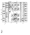
- FIG 1 shows an example of a master module 1 of the invention Installation system, which also as "stand alone” device can be used.
- This master module 1 provides a finished installation system in single operation and has four standard inputs I1, I2, I3 and I4 which are designed as floating inputs. In the present exemplary embodiment, these are potential-free Inputs I1 to I4 with one not detailed in detail Half-wave detection circuit 6, 7, 8 shown and 9 provided, the meaning of which will be explained in more detail later is received.
- These standard inputs I1 to I4 serve first to switch a consumer and are accordingly as standard one output C1, C2, Assigned to C3 and C4.
- the present Embodiment three central inputs ZE, ZA and AW provided, the central input ZE for the central function "Central ON", the central entrance ZA for the Central function "Central OFF” and the central input AW intended for the central function "presence simulation” is.
- the assignment of these central inputs ZE, ZA, AW the outputs C1 to C4 can be freely selected, as later will be explained later.
- the individual standard inputs I1 to I4 are here Function switches corresponding to the exemplary embodiment 14, 15, 16 and 17 assigned, about which certain Switching functions with a switching signal on corresponding standard input I1 to I4 can be selected or is adjustable.
- Function switch 14 to 17 is on the one hand the type of am associated standard input I1 to I4 applied switching signal in the form of a permanent switching or short-term Adjustable touch signal and on the other hand a timer function, like this for example with conventional Automatic staircase lighting is also used.
- Dependent on the position of the function switches 14, 15, 16 and 17 is at the corresponding standard input I1, I2, I3 and I4 expects either a switching signal or a key signal.
- Is the function switch 14 or 15 additional assigned a timer function this can be done under Setting a predetermined period of time set which causes the default associated or assigned output C1 or C2 via this Time function can be controlled, which will be explained in more detail later becomes.
- each output C1 to C4 is a button Assigned to T1, T2, T3 and T4, through which one Assignment of the associated outputs C1 to C4 to one Central function ZE, ZA or AW can be determined.
- a network connection 26 is also provided, which is fed via the normal mains voltage L and N. about a power supply 27 becomes a microprocessor 28 trained computing unit and on the other hand a communication interface 29, hereinafter referred to as COM, fed.
- COM communication interface
- This is also COM 29 or the computing unit 28 with a data memory 30 in the form of a EPROMs, in which various programmable presets are discardable. This serves in particular EPROM 30 for defining both the standard functions and also the central functions.
- indicator lights 35, 36, 37, 38, 39, 40, 41 and 42 are provided, which for optical control or setting certain operating states.
- indicator lights 35 to 42 are the standard inputs on the one hand I1 to I4 and on the other hand the outputs C1 assigned to C4. There are also three other indicator lights 43, 44 and 45 provided which for adjustment the pre-programmed central functions.
- Another Control lamp 46 is used to indicate the programming mode, during the pre-programming of the as microprocessor trained computing unit 28.
- a clock 47 is provided.
- the standard inputs I1 to I4 as well as the central inputs ZE, ZA and AW are designed for switching signals that derived from the phase of normal mains supply are. This means that these inputs I1 to I4 and ZE, ZA and AW to an operating voltage of 230 V as a voltage signal are designed.
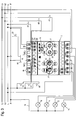
- Figure 2 shows an embodiment of a specific master module 1, which in the block diagram according to FIG 1 contains circuit arrangement shown. It is recognizable that all connections, i.e. both the inputs I1 to I4, ZE, ZA and AW as well as the outputs C1 to C4 as well as the communication interface 29 (COM) are designed as terminal connections, such as this common with normal, conventional automatic controls is. To these connections the inputs and outputs is additionally a potential-free universal input 48 provided which, for example, for coupling the master module is provided with an intercom. This potential-free universal input 48 is also in Figure 1 shown in block diagram.
- the standard inputs I1 to I3 are also potential-free Inputs formed and via the network connection N switched to "ground".
- the standard input I4 points a special feature in that it has an input terminal 49 is provided, which as a connection for a 230 V switching signal is used.
- This standard input I4 points a second terminal 50 on which this Standard input I4 can be switched separately to zero potential is.
- This special design allows this Input I4 via a current protection switch, a so-called FI switch to operate, in which case the terminal 50 via the FI switch to zero potential to be led.
- Such a configuration may be necessary be to the legal regulations regarding the Protection of certain circuits, for example in connection to be able to meet with wet cells.
- the function switch 14 to 17 are designed as rotary switches. These function switches 14 to 17 can optionally in one Position "S" or "T". Are these Function switches 14 to 17 to the "S" position set, as an example for the function switch 14 and 16 are shown, the corresponding corresponding Input I1 or I3 as a switching signal an ongoing Switching voltage of 230 V is expected, such as this more conventional when turning on a lighting fixture Kind of a normal light switch in the corresponding Living space is done. Is such a function switch in the "T" position as for the function switch 17 is shown, then at the associated input I4 a switching signal is expected as a switching signal, as is the case, for example is the case with staircase lighting.
- the central inputs ZE, ZA are also shown in FIG and AW recognizable, which in the present embodiment pre-programmable central functions, as already mentioned above, central ON, central OFF or one Presence simulation are assigned.
- FIG and AW recognizable, which in the present embodiment pre-programmable central functions, as already mentioned above, central ON, central OFF or one Presence simulation are assigned.
- FIG and AW recognizable, which in the present embodiment pre-programmable central functions, as already mentioned above, central ON, central OFF or one Presence simulation are assigned.
- Buttons T1 to T4 can be recognized by their actuation optional switching of the central functions ZE, ZA or AW on the corresponding output C1, C2, C3 or C4 can be effected.
- a further one also designed as a rotary switch Selector switch 55 is provided.
- This selector switch 55 is from a position "Auto” in the central functions corresponding positions "ZE", “ZA” and “AW” brought. These switch positions are with the indicator lights 43, 44 and 45, the respective Control lamp lights up if the selector switch is in this position is brought.
- the selector switch 55 is in the Position "ZA”. In this position there is a kind of programming of the outputs C1, C2, C3 and C4 feasible in in the sense that these outputs C1 to C4 alternatively by press one of their assigned buttons T1, T2, T3 or T4 can be assigned.
- the indicator lights 35, 37, 39 and 41 are used for identification in programming mode while the individual Switching functions of the standard functions can be programmed.
- the control lamp 46 is identified by the term "set”, which means that this indicator light 46 is activated is when the master module 1 is in programming mode located, this master module 1 via a in Figure 2 Interface not shown separately programmed externally is received and corresponding program information can.
- COM marked communication interface 29 also has two connections, their operation later is explained in more detail.
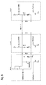
- FIG 3 shows a circuit arrangement in which the master module 1 is involved. Is not connected to this representation the universal entrance 48.
- the master module 1 is located with respect to the selector switch 55 in its normal operating state, which means that this selector switch 55, as can be seen from Figure 3, itself is in the "Auto" operating position.
- the function switch 14 is in the functional position "S", so that a conventional switch at the associated input I1 60 is provided for generating a permanent switching signal is.
- the function switch 15 is on the scale 53 directed and is in a time position, the when activating the associated function group a Timer triggers for a period of about 10 minutes. Since this function switch 15 in the time switch function is at the associated input I2 Key switch 61 connected.
- the function switch 16 is in the position "T” so that its function group on an input signal "Key signal” is set and accordingly on the associated Input I3 also connected to a push button switch 62 is.
- the switch 60 and the two buttons 61 and 62 are activated when activated via the corresponding Inputs I1, I2 and I3 via the terminal N of the Mains connection 26 against the neutral conductor N in FIG. 3 mains supply marked with L1, L2, L3 and N House installation switched.
- the function switch 17 is located as in FIG. 3 can be seen in the functional position "S", so that on corresponding input I4 a normal light switch 63 connected.
- the input I4 points in the present Embodiment two terminals I4 (N) and I4 (L) on, so that an FI switch is used for this input can be.
- the switch 63 is via this FI switch 64 connected to terminal I4 (L).
- the Switching to zero potential N is also carried out the FI switch 64, which on the one hand with the connecting terminal I4 (N) of input I4 and on the other hand with the neutral conductor the mains supply N is connected. Because of the special The design of the entrance I4 is legal Protective circuit corresponding to regulations, as prescribed for example for wet cells, feasible.
- the switches are located 60 and 63 and buttons 61 and 62 with their second Connection to phase L1 of the mains supply.
- FIG. 3 is the mode of operation such that when a Switching signal when switch 60 is closed at input I1 the output C1 is switched through, so that the consumer 70 supplied with a corresponding operating voltage becomes.
- Examples are consumers 70, 71, 72 and 73 designed as lights so that when concerns an interference signal at input I1 the light of the consumer 70 is turned on.
- consumer 71 it can for example, staircase lighting, which when the button 61 is pressed for, as already mentioned above, about 10 minutes can be activated. The means that when the button 61 is pressed for 10 minutes the output C2 is activated and the stairwell lighting 71 is switched on for 10 minutes. After expiration the staircase lighting 71 turns on again for 10 minutes off.
- the function group belonging to input I3 and output C3 with its function switch 16 is on the Function "key signal" set and works accordingly like a surge switch.
- The is called, the button 62 is actuated, so the output C3 the light 72 switched on and when pressed again of the push button 62 this light 72 is in turn switched off.
- Switching signal "push button signal” are pre-programmed.
- the assigned inputs I1 to I4 and the assigned outputs C1 to C4 are these Switching functions by programming the master module 1 permanently assigned. If necessary, this assignment however, be changed so that multiple inputs I1 to I4 and / or several outputs C1 to C4 one only function group I1, I2, I3 or I4 can be assigned are.
- the lighting device via the two inputs I1 and I4 71 is switchable.
- the two outputs C1 and C2 are switchable, see above that when the input I2 is activated, the two lighting devices or consumers 70 and 71 at the same time can be switched on.
- Terminal ZE central ON all lighting devices 70, 71, 72 and 73 are switchable.
- the method to assign outputs C1 to C4 to the central function "Central ON" has been described for FIG. 2.
- the switch 65 which is a If the button is pressed, the central entrance is activated and its function group activated and for example all outputs C1 to C4 switched through, so that all Consumers 70 to 73 can be switched on simultaneously. It is provided that this central function ZE has the highest priority, which means being independent from possibly present at inputs I1 to I4 or signals not present when the central input is activated ZE always switched consumers 70 to 73 become. If the button 65 is pressed again, then the "Central ON" function is switched off again. Is one the consumer 70, 71, 72 or 73 switched on because at whose corresponding input I1 to I4 a switching signal the associated consumer remains switched on.
- the "Central OFF" Function means that, for example, all outputs C1 to C4 when the input is activated for the first time ZA can be opened or switched off. That is, all Facilities or consumers 70 to 73 also are switched off. Is by pressing the button again 66 the "central OFF" function is switched off again, this turns a consumer 70 to 73 that was switched on in advance not automatically switched on again. There is provided that the associated switch 60, 63 or button 61, 62 must be pressed again to the corresponding Switch consumers 70 to 73 back on.
- the Function "central OFF” has a lower priority what means that if this function is activated and then the central function "Central ON” activated by pressing the button 65, all assigned Outputs C1 to C4 are switched through and thus all consumers 70 to 73 switched on again are.
- the third central function is a "Presence simulation", which can be activated using button 67 is.
- Presence simulation For the presence simulation are in one Memory area of the arithmetic unit of the master module one week all at switches 60, 63 and buttons 61, 62 made switching operations stored. Becomes The central input AW is activated via button 67, see above all run in chronological order over a week Switching operations as they were detected again. that is, that based on the recorded switching sequences when activated Presence simulation of these switching sequences automatically expire and an extremely realistic presence can be simulated is. It is provided that from week to week, if there are no new records, the switching times within certain limits through a kind of random programming be changed so that from week to Week outwards the impression arises that actually someone is in a building.
- the presence simulation has again compared to the a lower priority for the other two central functions, so that when presence simulation is activated Activation of the central function "Central OFF" all assigned outputs C1 to C4 deactivated and the corresponding associated consumers 70 to 73 switched off become.
- the standard inputs I1 to I4 with a half-wave detection circuit be provided.
- this half-wave detection circuit are the corresponding standard inputs from the mains supply different switching signals can be supplied. So can the phase of the standard inputs I1 to I4 as a solid wave, supplied lower half-wave or upper half-wave become. Due to the half-wave detection circuit the different switching signals from the computing unit as a switching signal for switching the intended central functions evaluable. In addition to the Central inputs also the standard inputs for activation of the central functions are used.
- the normal household budget Switch or button used. 4 shows this Embodiment of such a simple circuit, through which, for example, one of the half waves as Switching signal is generated.
- a diode circuit 81 is connected in parallel, the Signal via the switch 80 in the present embodiment a changeover circuit 82 is supplied.
- FIG. 5 shows an example in which three switches 85, 86 and 87 are provided, by which three different Switching signals generated and, for example, the input I1 of the master module 1 can be fed.
- the counter 85 is an ordinary switch, like it is used in a normal house installation.
- This Switch 85 is not assigned a diode circuit, so that when closing this switch 85, for example, the Standard function of function group I1 is switched.
- the switch 87 is also a diode circuit 89 downstream, which causes, for example only the lower half-wave switched through to input I1 becomes.
- the computing unit accordingly of the master module 1 can thus be of concern of such a negative half wave signal that, for example, the central function of presence simulation is activated.
- the priorities of this Central functions are identical to those described above. Also the assignment of the central functions to the outputs C1 to C4 via the selector switch 55 and the Buttons T1 to T4 are identical as described above.
- the installation system 100 is also according to the invention provided that the entire installation system 100 be modular is constructed.
- the installation system 100 consists of the Master 1, as previously described as well from further switching modules in the form of slave modules 90 and 91.
- the master module 1 points the master module 1, as already described, a computing unit in the form of the microprocessor 28, which one RAM and an EPROM 93 is assigned.
- the microprocessor 28 with the communication interface (COM) 29 in connection.
- the two in Figure 6 slave modules 90 and 91 which are further illustrated are in turn also with a computing unit in the form of a microprocessor 94 or 95 provided. These two microprocessors too 94 and 95 are working memories 96 or 97 and an EPROM 98 assigned.
- two slave modules 90 and 91 each have a communication interface 102 and 103 respectively.
- the switching modules, the Master module 1 and slave modules 90 and 91 protrude their communication interfaces 29, 102 and 103 via a two-wire connection 104 in communication. Since all switching modules, so the master module 1, like also the slave modules 90 and 91 in "stand alone" mode can work with this type of circuit Many slave modules in parallel to already installed slave modules can be added or removed without that the already installed switching modules are affected become.
- the control of the outputs of the slave modules 90 and 91 takes place on the one hand via its own standard inputs, as can be seen, for example, from FIG. 7, while the control of the outputs of these slave modules on the one hand through your own standard inputs can and on the other hand also through the assignment the central functions of the master module 1.
- the switching functions, which are present when a central signal is applied to the master module 1 to be switched through at the outputs of the slave modules are over the two-wire connection and the communication interfaces 29, 102 and 103 to the slave modules transfer. Will the connection between each Modules and consumers separately or one of the falls Modules off, so all modules are still there anyway they have their own standard inputs, continue for their own standard functions fully operational.
- a total of four switching modules are shown in FIG. being a master module 1, which will always be present must be provided, as well as three further slave modules 90, 91 and 105 are.
- the slave module 90 As from the lettering of the shown Switch module 1, 90, 91 and 105 emerges is the slave module 90 with the exception of the central entrances ZE, ZA, AW identical in structure to the master module 1 Slave module 90 also the standard inputs I1, I2, I3 and I4 on. Furthermore there is also a network connection provided by the terminals N and L is shown.
- Each of the standard inputs is I1 to I4 assigned a function group, which also with the Designations I1, I2, I3 and I4 are marked.
- This Function groups are also equipped with buttons on the output side T1, T2, T3 and T4 and corresponding control lights 107 to 114 provided. Furthermore is also a control lamp 115 labeled "set" provided which optically identifies the programming mode.
- These functional groups I1 to are also further I4 assigned a total of four outputs C1 to C4. The means that the slave module 90, like the master module 1 has a total of four channels and thus four circuits can be switched by any switching module.
- the slave module 91 has only two inputs I1 and I2, through which two function groups I1 and I2 are controllable. These two functional groups accordingly the functional groups in the present exemplary embodiment I3 and I4 of the master module 1, as in FIG. 2 described, although it should also be noted here that the slave module 90 these two function groups I3 and I4 having.
- These function groups I1 and I2 of the slave module 91 serve for simple switching operations, which either in a switching mode by the normal switch or can be activated by a pushbutton in a pushbutton mode.
- the slave module 91 in turn has two outputs C1 and C2 on, so that two slave circuits through this slave module 91 are switchable.
- the slave module 105 can, for example, be a programmable one Include controls for various functions. So can be a shutter control, for example act.
- This slave module 105 also has two inputs I1 and I2, which are also two function groups I1 and I2 are assigned. As exits are here also two pieces D1 and D2 are provided. When activated of inputs I1 and I2 are the two outputs D1 and D2 with appropriate programming of the function groups Appropriate switching sequences can be applied to I1 and I2. It can be seen that here too for each functional group I1 or I2 each have a function switch 116 or 117 is provided by their corresponding settings Programmable program sequences P1 to P4 are available. Furthermore, it can be seen from FIG.
- buttons T1 and T2 are provided, which the outputs C1 and C2 or D1 and D2 are assigned. Also by means of this Buttons T1 and T2 can be used for the corresponding outputs C1, C2 and D1, D2 via the communication interfaces, which are marked with COM on all modules, additionally with a central function.
- a programming module can also be used here 118 can be provided, which as a PC interface is trained.
- This programming interface too has a communication interface the COM marking, via which this programming interface in parallel with all switching modules 1, 90, 91 and 105 related to their programming stands.
- the master module 1 also with a USB interface Programming.
- the PC USB interface acts as a new master.
- the ID Number 0 is reserved for a master function. If this 0 is recognized during a query, then clicks the basic device in its master function, because it is only one master allowed.
- the USB interface then has the full master function with direct PC access. Is the USB function is no longer desired, then by command passed back to the device master and the system function manufactured.
- the USB interface is for manufacturing for configuration of devices provided for development at the same time to the device test. Later, if desired, the customer get the opportunity through this pc Interface its own assignment of inputs and Configure outputs of the LUXOR device.
- All devices connected to the COM interface are assigned the higher-level functions the central inputs ZE and ZA and AW as well as the assigned Half-wave detection.
- the master asks cyclically all slaves, whether there is a central function. Is this the master then distributes this message to everyone Participants configured for this by their ID number are.
- the central ON function "ZE" takes the highest priority on (panic button). No one else works during the ZE function Switch or button. This function can only be used by ZE be canceled again. After that, the last ones saved switching states restored and the Timer functions restarted.
- Presence simulation takes the lowest priority "AW". No one else works during the ZA function Switch or button. A switch with display activated the presence simulation. Just turning this off Switch can switch off the presence simulation. A ZE function can overlap this AW, as can one ZA function. The AW takes after pressing a ZA function their circuits back on.
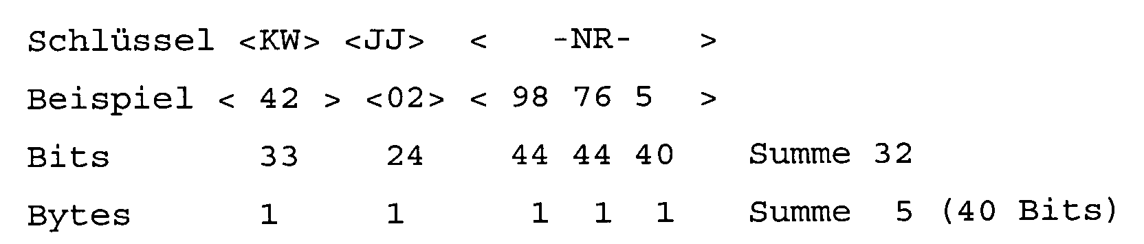
- the address is 40 bits long and is composed as follows:
- the device checks whether the Bus is functional; if not, sending will be instant canceled.
- the push button inputs transmit the mains voltage in the form from half-waves (HW) to the LUXOR device, i.e. to the respective Switching module.
- the switch module has 8 switch inputs too recognize and debounce, provided the system from the Switching modules 1, 90 and 91 from FIG. 7 consists. If three Half waves for debouncing are required 60 ms. So it is a button response time of 100 ms realizable.
- the inputs become parallel at 1 ms intervals queried and checked for debouncing in a counter.
- 5 function blocks are available. These can be used as a single function with a selector switch to get voted.
- the switch function switches after a debounce time and a network half-wave detection, the assigned outputs directly on ON / OFF. Is the switch input I1 ... I4 is live, so the assigned switching function executed and canceled again when de-energized.
- each button press is recognized saved and acts like at the assigned outputs an impulse switch.
- Network half-waves are also recognized and take on special functions.
- the master After a power failure, the master detects a reset and issues the command to report all participants (slaves). Each participant has his own ⁇ C, which recognizes this signal and reacts to it. For system reasons except for the master, all are in receive mode everyone tries to join after the master request to report his own device address, which he gave to the Device manufacturing, captive in an EPROM, with on got the way.
- the device address consists of the calendar week, the year and a 5-digit run number. A total of 99,999 devices can be differentiated per week.
- the address is 40 bits long and is composed as follows:
- the master goes after sending the command "report all” in the receiving company, listens there at his common Resistance of all slaves connected in parallel, below Circumstances at the same time, answer.
- a central function affects the whole system and will in the manual programming of the individual outputs, also for slaves, assigned and managed by the master
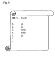
- the master starts after assigning his ID number new request in the polling process with the command report all participants. Every slave that has an ID Number has been confirmed, reports the new request no more. So there are less and less unconfirmed Slaves, e.g. ID 1, 2 and ID 5 are acknowledged and entered, as exemplified in Fig. 9. This with the new request for an ID number no longer mentioned. After the 15th request, everyone would have to Slave's recognized and provided with ID numbers.
- the slave recognizes this and deletes its own ID address. Then he can also move to a new system by adding a new ID number.
- the master receives after a multiple query of the ID number acknowledged him no response from the slave, so he deletes this ID number in his EPROM so that this Number is free again for new participants.
- the device If there is no device in the system, i.e. no COM Connection, and therefore no ID number assigned by a Master, the device is fully functional in its functions and can have its own central functions if they have been triggered by this device (Stand alone). A central function spanning the system can not.
- the devices receive their basic configuration after production through a PC system configuration software.
- Each Function block is its associated input and its associated output assigned. For example, the function block 2 the input I2 and the output C2 are assigned.
- the Function assignment of a function block is device-specific designed.
- the system (master) detects a USB interface, see above it receives the full master role. Via the COM All connected participants are in the interface Readiness for configuration set. All participants except the master in the system, signal theirs at the same time Readiness for configuration by simultaneous Flashing of the green LEDs I1 and I2 in a blinking rhythm 2/3 on, 1/3 off.
- the salvo signals its readiness by switching it off the LED flashing function and at the same time permanent Turn on his red SET LED.
- the Configuration readiness reported to the USB interface this then deactivates the remaining slaves. These remaining slaves go into their normal operation without LED status messages.
- a simultaneous configuration of several system participants may be possible, but is not currently planned.
- the function blocks on the PC are used to select their functions, displayed with a click of the mouse.
- the relay response times are 7 ms and the remanence times at 3ms.
- a 50 ms pulse will be reached with each switch-on process output directly before the 1 ⁇ 2 KHz clock signal. This 50 ms pulse is given every 5 seconds during the relay on phase repeated, so that network dips are safe again be switched on.
- the SET LED red is active without flashing:
- One of the central ON / OFF / AW functions is selected using the rotary switch.
- the SET LED flashes red in the basic device:
- the "BUS" has a short circuit or is not connected.
- the green LEDs I1 and I2 flash in the rhythm 2/3 - 1/3 light / dark: After sending the configuration command, all system participants, except the master, signal their readiness for a configuration.
Landscapes
- Engineering & Computer Science (AREA)
- Power Engineering (AREA)
- Circuit Arrangement For Electric Light Sources In General (AREA)
- Selective Calling Equipment (AREA)
- Stored Programmes (AREA)
Abstract
Description
- Fig. 1
- ein Blockschaltbild eines als Mastermodul ausgebildeten Schaltmoduls des erfindungsgemäßen Installationssystems;
- Fig. 2
- die Frontansicht des Mastermoduls aus Fig.1 mit seinen Anschlüssen und Wahlschaltern;
- Fig. 3
- eine Schaltungsanordnung des Mastermoduls aus Fig. 1 und 2 mit angeschlossenen Verbrauchern und Schaltern;
- Fig. 4
- ein Blockschaltbild eines Schalters mit einer Schaltererweiterung;
- Fig. 5
- eine Schalterkombination mit unterschiedlichen Schaltfunktionen und unterschiedlichen Erweiterungsmodulen;
- Fig. 6
- eine Prinzipdarstellung von mehreren miteinander kombinierten Schaltmodulen;
- Fig. 7
- die Frontansicht von mehreren miteinander kombinierten Schaltmodulen;
- Fig. 8
- ein Schaltungsbeispiel dreier Module, deren COM-Schnittstelle an einen gemeinsamen Widerstand des Mastermoduls führen;
- Fig. 9
- eine interne Belegliste des Masters.

Mit dem Drehschalter ist eine der Funktionen Zentral EIN/AUS/AW gewählt.
Der "BUS" hat Kurzschluss oder ist nicht verbunden.
Nach dem Senden des Befehls Konfiguration signalisieren alle Systemteilnehmer, außer dem Master, ihre Bereitschaft für eine Konfiguration.
Claims (21)
- Installationssystem (100) zur Steuerung einer elektrischen Gebäudeinstallation mit einer programmierbaren Recheneinheit (28), welcher zur Schaltung elektrischer Verbraucher (70, 71, 72, 73) über Steuerleitungen Steuersignale zuführbar sind,
dadurch gekennzeichnet, daß in der Recheneinheit (28, 94, 95) mehrere, unterschiedliche Schaltvorgänge steuernde Funktionsgruppen (I1, I2, I3, I4, ZE, ZA, AW) zur Steuerung von Standard- und Zentralfunktionen (ZE, ZA, AW) gespeichert sind, die wahlweise einem oder mehreren Eingängen (I1, I2, I3, I4, ZE, ZA, AW) der Recheneinheit (28, 94, 95) zuordenbar sind, und
daß einzelne oder alle Funktionsgruppen (I1 bis I4) einem oder mehreren Ausgängen (C1, C2, C3, C4, D1, D2) der Recheneinheit (28, 94, 95) derart zuordenbar sind, daß bei Anliegen eines Steuersignals an einem der Eingänge (I1 bis I4, ZE, ZA, AW) die an den entsprechend zugeordneten Ausgängen (C1, C2, C3, C4, D1, D2) angeschlossenen Verbraucher (70 bis 73) gleichzeitig mit der entsprechenden Schaltfunktion der aktivierten Funktionsgruppe (I1 bis I4, ZE, ZA, AW) schaltbar sind und,
daß die Recheneinheit (28) für die Zuordnung der Zentralfunktionen (ZE, ZA, AW) zu den Ausgängen (C1 bis C4, D1, D2) zusätzlich mit manuell bedienbaren Tastern (T1, T2, T3, T4) versehen ist. - Installationssystem nach Anspruch 1, dadurch gekennzeichnet, daß die Recheneinheit (28) Funktionsgruppen (ZE, ZE, AW) aufweist, die zentrale Schaltvorgänge bewirken und, daß jeder Funktionsgruppe (ZE, ZE, AW) ein Zentraleingang (ZE, ZE, AW) zugeordnet ist und, daß die Zentralfunktionen (ZE, ZE, AW) wahlweise mehreren identischen und/oder verschiedenen Ausgängen (C1 bis C4, D1, D2) zuordenbar sind.
- Installationssystem nach Anspruch 1, dadurch gekennzeichnet, daß wenigstens ein Standardeingang (I1 bis I4) vorgesehen ist, welcher einer oder mehreren Funktionsgruppen (I1 bis I4) zuordenbar ist, die einen zentralen Schaltvorgang bewirken und,
daß der Standardeingang (I1 bis I4) einer Funktionsgruppe (I1 bis I4) zuordenbar ist, die eine Standardfunktion bewirkt und,
daß der Standardeingang (I1 bis I4) mit einer Signalerkennungsschaltung (6, 7, 8, 9) versehen ist, durch welche unterschiedliche, am Standardeingang (I1 bis I4) anliegende Schaltsignale auswertbar sind und,
daß die Recheneinheit (28) in Abhängigkeit des jeweiligen Eingangssignals die Standardfunktion (I1 bis I4) oder die Zentralfunktion (ZE, ZA, AW) aktiviert. - Installationssystem nach Anspruch 2 und 3, dadurch gekennzeichnet, daß zur Schaltung der Zentralfunktionen (ZE, ZA, AW) und der Standardfunktionen (I1 bis I4) sowohl Zentraleingänge (ZE, ZA, AW) als auch Standardeingänge (I1 bis I4) mit Signalerkennungsschaltung (6, 7, 8, 9) vorgesehen sind.
- Installationssystem nach einem der Ansprüche 1 bis 4, dadurch gekennzeichnet, daß die Auswahl einer Zentralfunktion durch einen Wahlschalter (55) erfolgt, der aus einer neutralen Automatikstellung (Auto) in eine die jeweiligen Zentralfunktion kennzeichnende Stellung (ZE, ZA, AW) bringbar ist und,
daß den Ausgängen (C1 bis C4, D1, D2) jeweils ein Taster (T1, T2, T3, T4) zugeordnet ist, durch dessen Betätigung der jeweils zugehörige Ausgang (C1 bis C4, D1, D2) der gewählten Zentralfunktion (ZE, ZA, AW) zuordenbar ist und,
das nach Zuordnung aller gewünschten Ausgänge (C1 bis C4, D1, D2) der Wahlschalter (55) in seine neutrale Automatikstellung (Auto) rückstellbar ist und die getroffene Auswahl der Ausgänge (C1 bis C4, D1, D2) für die gewählte Zentralfunktion (ZE, ZA, AW) in der Recheneinheit (28) abgespeichert wird. - Installationssystem nach einem der Ansprüche 1 bis 5, dadurch gekennzeichnet, daß jeder Funktionsgruppe (I1 bis I4) zur Schaltung einer Standardfunktion (I1 bis I4) ein Funktionsschalter (14, 15, 16, 17, 116, 117) zugeordnet ist, durch welchen die Schaltungsart eines Standardsignals wahlweise auf den Wert "Schaltsignal" oder "Tastsignal" einstellbar ist.
- Installationssystem nach einem der Ansprüche 1 bis 6, dadurch gekennzeichnet, daß wenigstens eine Funktionsgruppe (I1, I2) zur Schaltung einer Standardfunktion eine Zeitschaltfunktion aufweist.
- Installationssystem nach Anspruch 7, dadurch gekennzeichnet, daß die Zeitschaltfunktion mittels eines Funktionsschalters (14, 15) anwählbar ist und, daß mittels dieses Funktionsschalters (14, 15) wahlweise auch die Schaltungsart eines Standardsignals wahlweise auf den Wert "Schaltsignal" oder "Tastsignal" einstellbar ist, und daß über den Funktionsschalter (14, 15) das Zeitintervall für die Zeitschaltfunktion einstellbar ist.
- Installationssystem nach einem der Ansprüche 1 bis 8, dadurch gekennzeichnet, daß die eingestellten oder programmierten Funktionen und Zuordnungen der Einund Ausgänge (I1 bis I4, ZE, ZA, AW und C1 bis C4, D1, D2) mittels optischer Anzeigeelemente (35, 36, 37, 38, 39, 40, 41, 42, 43, 44, 45, 46, 107, 108, 109, 110, 111, 112, 113, 114, 115) anzeigbar ist.
- Installationssystem nach einem der Ansprüche 1 bis 9, dadurch gekennzeichnet, daß als Schaltsignal zur Aktivierung der Funktionsgruppen (I1 bis I4, ZE, ZA, AW) die Phase (L1, L2, L3) der Netzspannung verwendet wird.
- Installationssystem nach Anspruch 3 oder 4, dadurch gekennzeichnet, daß als Schaltsignal zum Aktivieren einer Zentralfunktion (ZE, ZA, AW) über einen Standardeingang (I1, bis I4) die obere, untere Netzhalbwelle oder die volle Sinuswelle der Netzspannung verwendet wird und,
daß der entsprechende Standardeingang (I1 bis I4) zur Signalerkennung eine Halbwellenerkennungsschaltung (6, 7, 8, 9) aufweist. - Installationssystem nach einem der Ansprüche 1 bis 11, dadurch gekennzeichnet, daß der Ausgang (C1 bis C4, D1, D2) jeder einzelnen Funktionsgruppe mit zwei Anschlüssen versehen ist, von welchen einer an der Phase (L1, L2, L3) der Netzversorgung unabhängig von der Steuerphase (L1, L2, L3) des zugehörigen Eingangs (I1, I2, I4, ZE, ZA, AW) angeschlossen ist und,
daß der zweite Anschluss des Ausgangs (C1 bis C4, D1, D2) zum jeweils anzusteuernden Verbraucher (70, 71, 72, 73) führt und,
daß bei Aktivierung des Ausgangs (C1 bis C4, D1, D2) die Phase (L1, L2, L3) zum Verbraucher (70 bis 73) durchschaltbar ist. - Installationssystem nach einem der Ansprüche 1 bis 12, dadurch gekennzeichnet, daß die Recheneinheit (28) mit einer Schnittstelle (118) versehen ist, über welche eine externe Programmierung der Schaltfunktionen der Funktionsgruppen (I1 bis I4, ZE, ZA, AW) durchführbar ist und,
daß über diese Schnittstelle (118) eine gewünschte Zuordnung der Eingänge, Ausgänge und Funktionsgruppen voreinstellbar ist. - Installationssystem nach einem der Ansprüche 1 bis 12, dadurch gekennzeichnet, daß mehrere mit einer oder mehreren Schaltfunktionen versehene Schaltmodule (1, 90, 91, 105) vorgesehen sind und,
daß jedes der Schaltmodule eine Kommunikationsschnittstelle (COM, 29, 102, 103) aufweist, über welche die Schaltmodule (1, 90, 91, 105) über eine Zweidrahtverbindung (104) parallel miteinander verbunden sind und untereinander kommunizieren. - Installationssystem nach Anspruch 13, dadurch gekennzeichnet, daß ein Schaltmodul als Mastermodul (1) mit einer Hauptrecheneinheit (28) ausgebildet ist und mit den Zentralfunktionen (ZE, ZA, AW) versehen ist und, daß die weiteren Schaltmodule (90, 91, 105) als Slavemodule mit unterschiedlichen Schaltfunktionen (I1 bis I4) ausgebildet und jeweils mit einem Mikroprozessor (94, 95) versehen sind und,
das die Zentralfunktionen (ZE, ZA, AW) des Mastermoduls (1) über die Kommunikationsschnittstellen (COM, 29, 102, 103) den Ausgängen (C1 bis C4, D1, D2) der Slavemodule (90, 91, 105) über Taster (T1 bis T4) der Slavemodule (90, 91, 105) zuordenbar sind. - Installationssystem nach Anspruch 14 oder 15, dadurch gekennzeichnet, das jedes Schaltmodul (1, 90, 91, 105) mit eigenen Eingängen (I1 bis I4) und Ausgängen (C1 bis C4, D1, D2) versehen ist und bei Unterbrechung des Kommunikationsflusses über die Kommunikationsschnittstelle (COM, 29, 102, 103) als eigenständiges Schaltmodul fungiert und seine eigenen Standardschaltfunktionen (I1 bis I4) weiterhin bei Anliegen eines Schaltsignals am eigenen Eingang (I1 bis I4) ausführt.
- Installationssystem nach einem der Ansprüche 14 bis 16, dadurch gekennzeichnet, daß jedes der Schaltmodule (1, 90, 91, 105) mit einer eindeutigen Geräteadresse ausgestattet ist und,
daß die Geräteadresse aus der Kalenderwoche und dem Jahr der Herstellung des Schaltmoduls in Kombination mit einer fünfstelligen Durchlaufnummer besteht und, daß diese Geräteadresse über die Kommunikationsschnittstelle (COM, 29, 102, 103) an das Mastermodul (1) übergebbar und dort abspeicherbar ist. - Installationssystem nach einem der Ansprüche 1 bis 17, dadurch gekennzeichnet, daß den Zentralfunktionen (ZE, ZA, AW) eine höhere Priorität zugewiesen ist als den Standardfunktionen (I1 bis I4), so daß bei Aktivierung einer Zentralfunktion (ZE, ZA, AW) diese stets ausgeführt wird, unabhängig davon, ob eine Standardfunktion (I1 bis I4) aktiviert ist.
- Installationssystem nach einem der Ansprüche 14 bis 18, dadurch gekennzeichnet, daß den Zentralfunktionen (ZE, ZA, AW) untereinander unterschiedliche Pioritäten zugewiesen sind und,
daß manuell schaltbare Zentralfunktionen (ZE, ZA) Vorrang vor automatisch ablaufenden Zentralfunktionen (AW) haben. - Installationssystem nach einem der Ansprüche 1 bis 19, dadurch gekennzeichnet, daß als Zentralfunktion eine Anwesenheitssimulation (AW) vorgesehen ist und, daß die Schaltfunktionen der Anwesenheitssimulation (AW) innerhalb einer Woche anhand der manuellen Schaltvorgänge in einer Gebäudeinstallation aufgezeichnet und in einem Speicher der Recheneinheit (28) bzw. Hauptrecheneinheit (28) aufgezeichnet werden und bei aktivierter Anwesenheitssimulation (AW) anhand der aufgezeichneten Schaltzeiten automatisch ablaufen.
- Installationssystem nach Anspruch 20, dadurch gekennzeichnet, daß die Schaltzeiten beim Ablauf der Anwesenheitssimulation (AW) für jeden wöchentlichen Durchlauf nach einem Zufallsprogramm in vorbestimmbaren zeitlichen Grenzen veränderbar sind.
Applications Claiming Priority (2)
| Application Number | Priority Date | Filing Date | Title |
|---|---|---|---|
| DE10327504A DE10327504B4 (de) | 2003-06-17 | 2003-06-17 | Multifunktionsgerät |
| DE10327504 | 2003-06-17 |
Publications (2)
| Publication Number | Publication Date |
|---|---|
| EP1489718A2 true EP1489718A2 (de) | 2004-12-22 |
| EP1489718A3 EP1489718A3 (de) | 2010-09-01 |
Family
ID=33394872
Family Applications (1)
| Application Number | Title | Priority Date | Filing Date |
|---|---|---|---|
| EP04013865A Withdrawn EP1489718A3 (de) | 2003-06-17 | 2004-06-14 | Elektrisches Installationsgerät |
Country Status (2)
| Country | Link |
|---|---|
| EP (1) | EP1489718A3 (de) |
| DE (1) | DE10327504B4 (de) |
Cited By (7)
| Publication number | Priority date | Publication date | Assignee | Title |
|---|---|---|---|---|
| EP1843446A1 (de) * | 2006-04-05 | 2007-10-10 | Zumtobel Lighting GmbH | Anschlusseinrichtung für die Hausleittechnik |
| WO2011076387A3 (de) * | 2009-12-23 | 2011-09-22 | Schneider Electric Industries Sas | Elektrisches installationssystem |
| DE102010050748A1 (de) * | 2010-11-08 | 2012-05-10 | Schneider Electric Industries Sas | Elektrisches Installationsgerät |
| NL1038594C2 (nl) * | 2011-02-18 | 2012-08-21 | Ten Holter Const B V | Intelligent besturingssysteem voor aansturen van decentraal geplaatste schakelcomponenten. |
| EP2830081A1 (de) * | 2013-07-24 | 2015-01-28 | Siemens Aktiengesellschaft | Parametrierung eines Schaltgerätes |
| CN110492610A (zh) * | 2019-08-15 | 2019-11-22 | 南京电博能源科技有限公司 | 一种允许带电操作的拓扑识别系统 |
| CN115542809A (zh) * | 2022-09-30 | 2022-12-30 | 佛山食神网络智能科技有限公司 | 一种通用控制器 |
Families Citing this family (4)
| Publication number | Priority date | Publication date | Assignee | Title |
|---|---|---|---|---|
| DE102005011378A1 (de) * | 2005-03-11 | 2006-09-21 | Kermi Gmbh | Temperaturregelvorrichtung für eine Heizvorrichtung, insbesondere einen Badheizkörper |
| DE102008048619A1 (de) * | 2008-09-23 | 2010-04-15 | Heinz Siegel | Verfahren und Steuerwerk zum elektrischen Steuern und/oder Regeln |
| DE102010017088A1 (de) * | 2010-05-26 | 2011-12-01 | Münchner Hybrid Systemtechnik GmbH | Schaltbare Stromversorgung |
| DE102013106794B4 (de) * | 2013-06-28 | 2015-05-07 | Hadler Gmbh | Beleuchtungsinstallation |
Family Cites Families (12)
| Publication number | Priority date | Publication date | Assignee | Title |
|---|---|---|---|---|
| US4719532A (en) * | 1986-02-26 | 1988-01-12 | Schneider Russell E | Electrical controller |
| DE3913266A1 (de) * | 1989-04-22 | 1990-10-25 | Bosch Gmbh Robert | Schaltungsanordnung fuer kraftfahrzeuge mit mehreren elektrischen verbrauchern |
| EP0639039A1 (de) * | 1993-08-11 | 1995-02-15 | Awag A. Widmer AG | Verfahren zur Programmierung einer Beleuchtungssteuerung oder einer Storensteuerung |
| DE4425876A1 (de) * | 1994-07-09 | 1996-01-11 | Wolfgang Dipl Jur Reimann | Intelligente Steckdose |
| DE29501535U1 (de) * | 1995-02-01 | 1995-04-06 | Grässlin KG, 78112 St Georgen | Programmierbare elektrische oder elektronische Schaltvorrichtung für die Elektroinstallationstechnik, insbesondere für die Gebäudesystemtechnik |
| DE19543380A1 (de) * | 1995-11-21 | 1997-06-05 | Sonlux Licht Und Elektroinstal | Verfahren und Schaltung zur Steuerung elektrischer Verbraucher |
| DE19544027C2 (de) * | 1995-11-25 | 1999-01-07 | Bernward Dr Zimmermann | Bussystem, insbesondere zur elektrischen Installation |
| DE19610420A1 (de) * | 1996-03-16 | 1997-09-18 | Insta Elektro Gmbh & Co Kg | Lichtschalter zur Anwesenheitssimulation |
| DE29611227U1 (de) * | 1996-06-27 | 1996-09-05 | Boyko Strey GmbH & Co. KG, 67133 Maxdorf | Steuereinrichtung für elektrische Verbraucher |
| DE19640300A1 (de) * | 1996-09-30 | 1998-04-02 | Siemens Ag | Installationssystem |
| CH693580A5 (de) * | 1998-08-18 | 2003-10-15 | Raymond Kleger | Verfahren zur Steuerung von Elektro-Installationen in Gebäuden und eine Steuerungsanordnung für die Steuerung von Elektro-Installationen in Gebäuden. |
| DE19944584A1 (de) * | 1999-09-17 | 2001-03-22 | Goetz Heuchemer | System zur Steuerung von räumlich verteilten elektrischen Verbrauchern in Gebäuden |
-
2003
- 2003-06-17 DE DE10327504A patent/DE10327504B4/de not_active Expired - Fee Related
-
2004
- 2004-06-14 EP EP04013865A patent/EP1489718A3/de not_active Withdrawn
Cited By (10)
| Publication number | Priority date | Publication date | Assignee | Title |
|---|---|---|---|---|
| EP1843446A1 (de) * | 2006-04-05 | 2007-10-10 | Zumtobel Lighting GmbH | Anschlusseinrichtung für die Hausleittechnik |
| WO2011076387A3 (de) * | 2009-12-23 | 2011-09-22 | Schneider Electric Industries Sas | Elektrisches installationssystem |
| RU2560124C2 (ru) * | 2009-12-23 | 2015-08-20 | Шнейдер Электрик Эндюстри Сас | Электрическая инсталляционная система |
| DE102010050748A1 (de) * | 2010-11-08 | 2012-05-10 | Schneider Electric Industries Sas | Elektrisches Installationsgerät |
| NL1038594C2 (nl) * | 2011-02-18 | 2012-08-21 | Ten Holter Const B V | Intelligent besturingssysteem voor aansturen van decentraal geplaatste schakelcomponenten. |
| EP2830081A1 (de) * | 2013-07-24 | 2015-01-28 | Siemens Aktiengesellschaft | Parametrierung eines Schaltgerätes |
| CN110492610A (zh) * | 2019-08-15 | 2019-11-22 | 南京电博能源科技有限公司 | 一种允许带电操作的拓扑识别系统 |
| CN110492610B (zh) * | 2019-08-15 | 2023-01-17 | 南京电博能源科技有限公司 | 一种允许带电操作的拓扑识别系统 |
| CN115542809A (zh) * | 2022-09-30 | 2022-12-30 | 佛山食神网络智能科技有限公司 | 一种通用控制器 |
| CN115542809B (zh) * | 2022-09-30 | 2024-02-20 | 佛山食神网络智能科技有限公司 | 一种通用控制器 |
Also Published As
| Publication number | Publication date |
|---|---|
| DE10327504B4 (de) | 2007-05-03 |
| EP1489718A3 (de) | 2010-09-01 |
| DE10327504A1 (de) | 2005-01-20 |
Similar Documents
| Publication | Publication Date | Title |
|---|---|---|
| WO1999048251A1 (de) | Verfahren zum inbetriebnehmen eines bussystems sowie entsprechendes bussystem | |
| DE4425876A1 (de) | Intelligente Steckdose | |
| EP3189382B1 (de) | Verfahren zur datenerhebung für die konfiguration eines gebäudeautomationssystems und verfahren zum konfigurieren eines gebäudeautomationssystems | |
| DE10327504B4 (de) | Multifunktionsgerät | |
| DE19544027C2 (de) | Bussystem, insbesondere zur elektrischen Installation | |
| EP3416337B1 (de) | Vorrichtung zur automation eines hauses oder gebäudes | |
| EP1756681A2 (de) | Hausgerätesteuerungssystem | |
| EP0982642A2 (de) | Verfahren zur Steuerung von Elektro-Installationen in Gebäuden und eine Steuerungsanordnung für die Steuerung von Elektro-Installationen in Gebäuden | |
| EP3070549B1 (de) | Bedieneinrichtung, verfahren zur bedienung wenigstens eines elektrischen geräts | |
| DE3222213A1 (de) | Einrichtung zur temperatursteuerung der einzelraeume eines gebaeudes | |
| DE10312183A1 (de) | Gebäudeinstallationssystem | |
| EP1993010B1 (de) | Sensoreinheit | |
| EP1734636A2 (de) | Schaltdose | |
| EP2299340A1 (de) | Zentrale, System und Verfahren zur Steuerung von Funktionseinrichtungen in Gebäuden | |
| EP1971080B1 (de) | Verfahren zur Inbetriebnahme eines Funksystems | |
| CH705430B1 (de) | Gebäudeautomatisierung. | |
| DE102011075608A1 (de) | Verfahren zum Zuordnen eines physikalischen Kanals eines Sensors, der an einen Bus eines Bus-Systems angeschlossen ist, zu einem Kanal eines in einem Inbetriebnahmeprogramm virtuell dargestellten Sensors sowie Sensor und Inbetriebnahmeprogramm | |
| DE10012279A1 (de) | System und Verfahren zum grafischen Verschalten von Elektroinstallationskomponenten | |
| EP3657272A1 (de) | Bediengerät für die hausautomatisierung | |
| AT515724B1 (de) | Benutzerkonfigurierbare Automatisierungsinstallation | |
| EP1843446B1 (de) | Anschlusseinrichtung für die Hausleittechnik | |
| EP3657286A1 (de) | Verfahren zum einrichten eines ansteuergerätes in einem gebäudeinstallationsnetzwerk | |
| WO2013104695A1 (de) | System zum ansteuern von aktoren, insbesondere von leuchten, mit abfragen von eingabe- /kontroll - einheiten | |
| DE102011015605A1 (de) | Heimnetzwerk zur Ansteuerung von Geräten | |
| AT510104A2 (de) | Benutzerkonfigurierbare automatisierungsinstallation |
Legal Events
| Date | Code | Title | Description |
|---|---|---|---|
| PUAI | Public reference made under article 153(3) epc to a published international application that has entered the european phase |
Free format text: ORIGINAL CODE: 0009012 |
|
| AK | Designated contracting states |
Kind code of ref document: A2 Designated state(s): AT BE BG CH CY CZ DE DK EE ES FI FR GB GR HU IE IT LI LU MC NL PL PT RO SE SI SK TR |
|
| AX | Request for extension of the european patent |
Extension state: AL HR LT LV MK |
|
| PUAL | Search report despatched |
Free format text: ORIGINAL CODE: 0009013 |
|
| AK | Designated contracting states |
Kind code of ref document: A3 Designated state(s): AT BE BG CH CY CZ DE DK EE ES FI FR GB GR HU IE IT LI LU MC NL PL PT RO SE SI SK TR |
|
| AX | Request for extension of the european patent |
Extension state: AL HR LT LV MK |
|
| RIC1 | Information provided on ipc code assigned before grant |
Ipc: H05B 37/02 20060101ALI20100728BHEP Ipc: H01H 47/00 20060101ALI20100728BHEP Ipc: G08C 19/28 20060101ALI20100728BHEP Ipc: H02J 13/00 20060101AFI20040726BHEP |
|
| AKY | No designation fees paid | ||
| STAA | Information on the status of an ep patent application or granted ep patent |
Free format text: STATUS: THE APPLICATION IS DEEMED TO BE WITHDRAWN |
|
| 18D | Application deemed to be withdrawn |
Effective date: 20110302 |